Force–Displacement Hysteresis Model of Exterior PCRB Joints under Low Cyclic Loading
Abstract
1. Introduction
2. Experimental Program
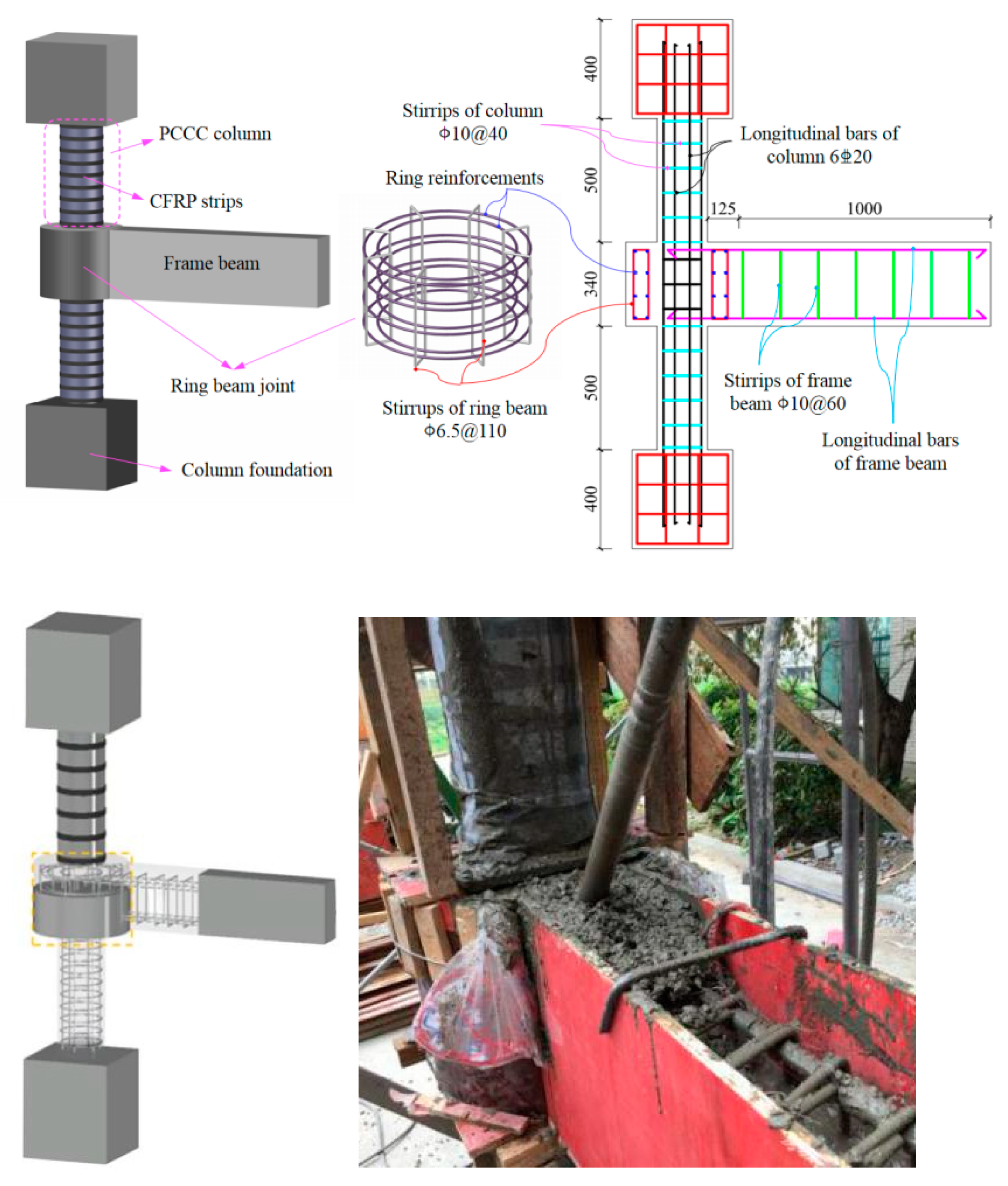
2.1. Test Specimens and Material Properties
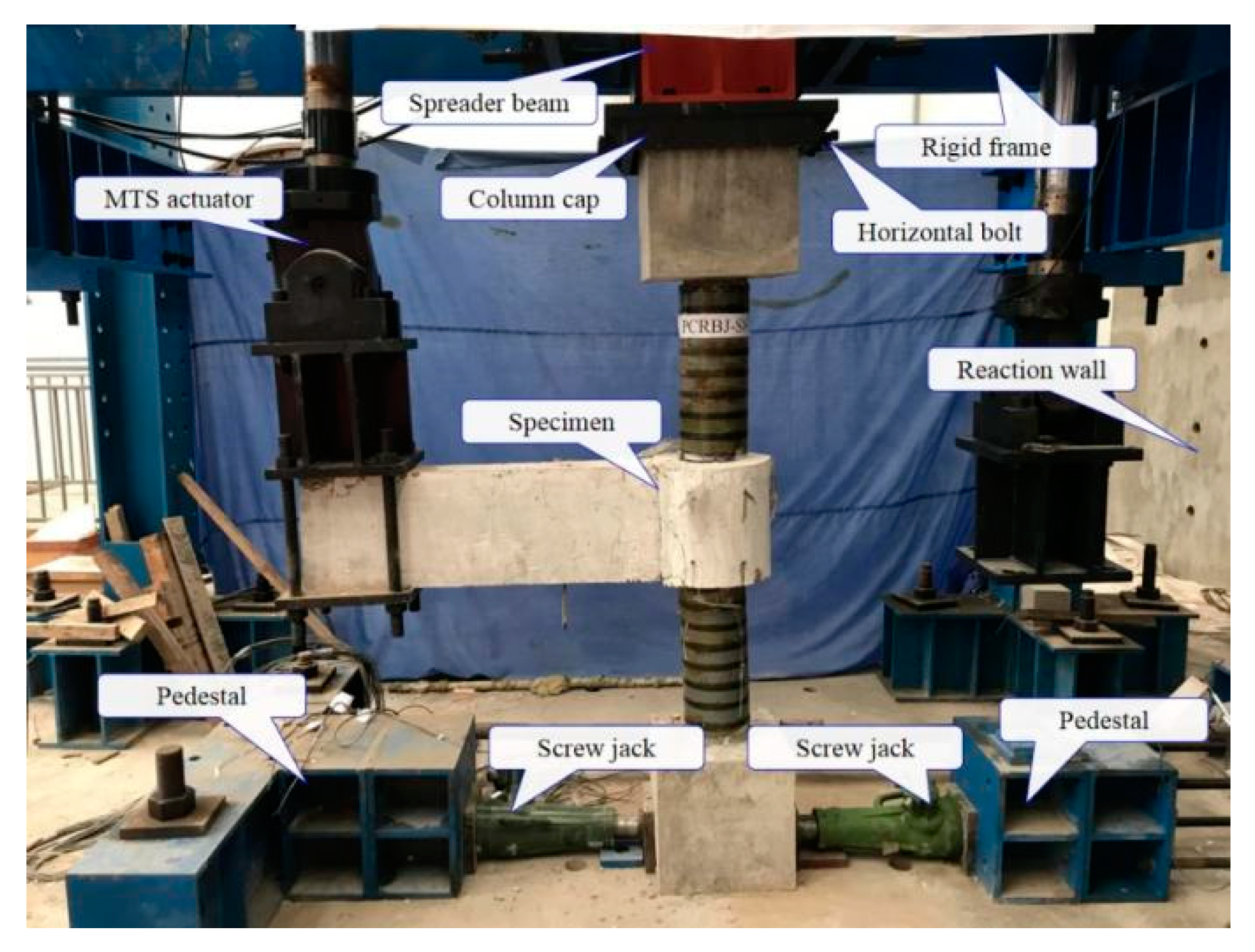
2.2. Test Setup
3. Experimental Results and Discussion
3.1. Failure Modes
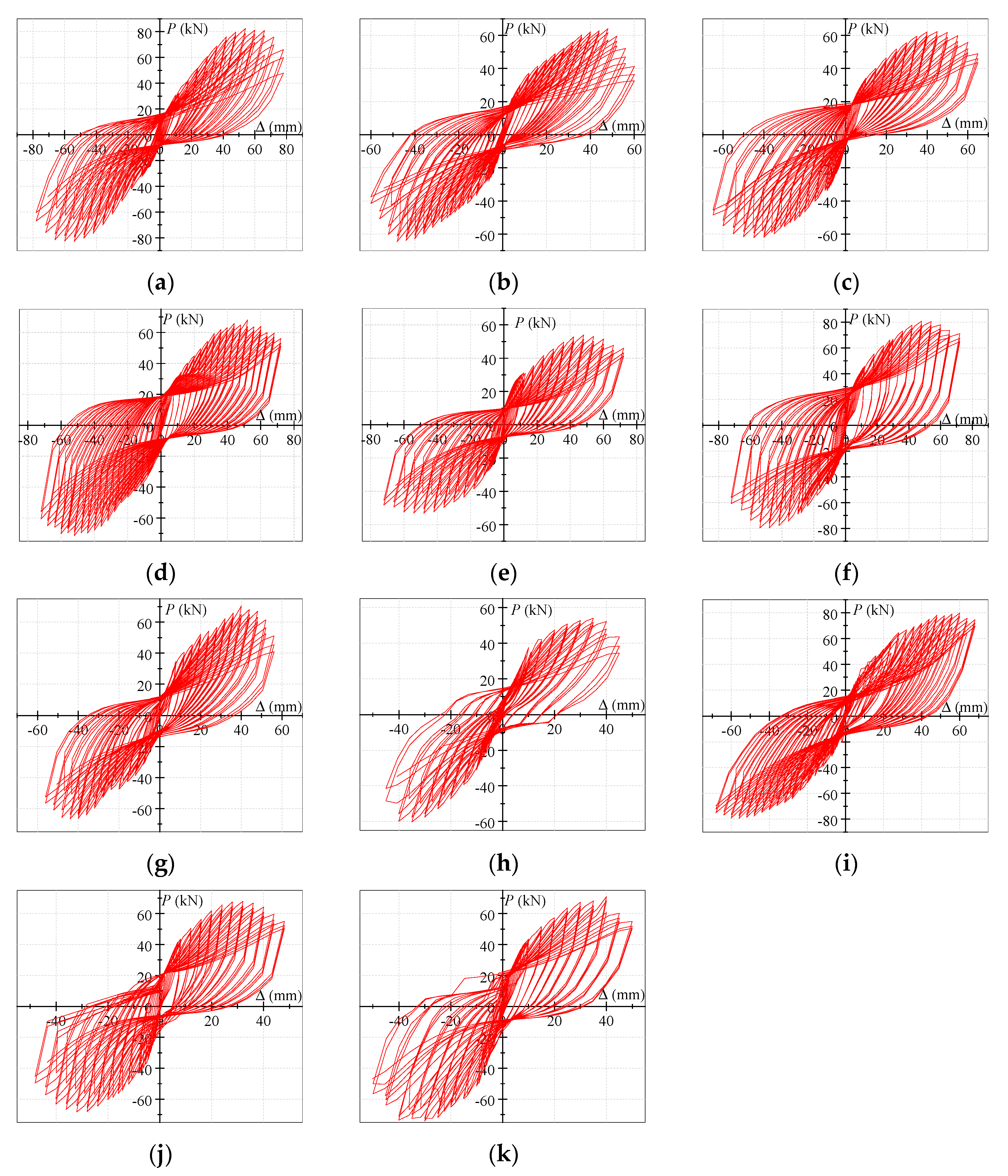
3.2. Hysteretic-Response Analysis
3.3. Skeleton-Curve Analysis
3.3.1. Skeleton-Curve Features
3.3.2. Effects of Reinforcement Ratio of Ring Beam
3.3.3. Effects of CFRP-Strip Spacing
3.3.4. Effects of Ring-Beam Width
3.3.5. Effects of Axial Compression Ratio
3.3.6. Effects of Reinforcement Ratio of Frame Beam
4. P–Δ Hysteresis Model of Exterior PCRB Joints
4.1. Basic Assumptions
- (1)
- The frame-beam section conforms to the plane-section hypothesis.
- (2)
- The tensile action of the concrete is ignored.
- (3)
- The effects of ring-beam-core-concrete shrinkage and creep are neglected.
- (4)
- The constitutive relation of the reinforcement is a bi-linear model.
- (5)
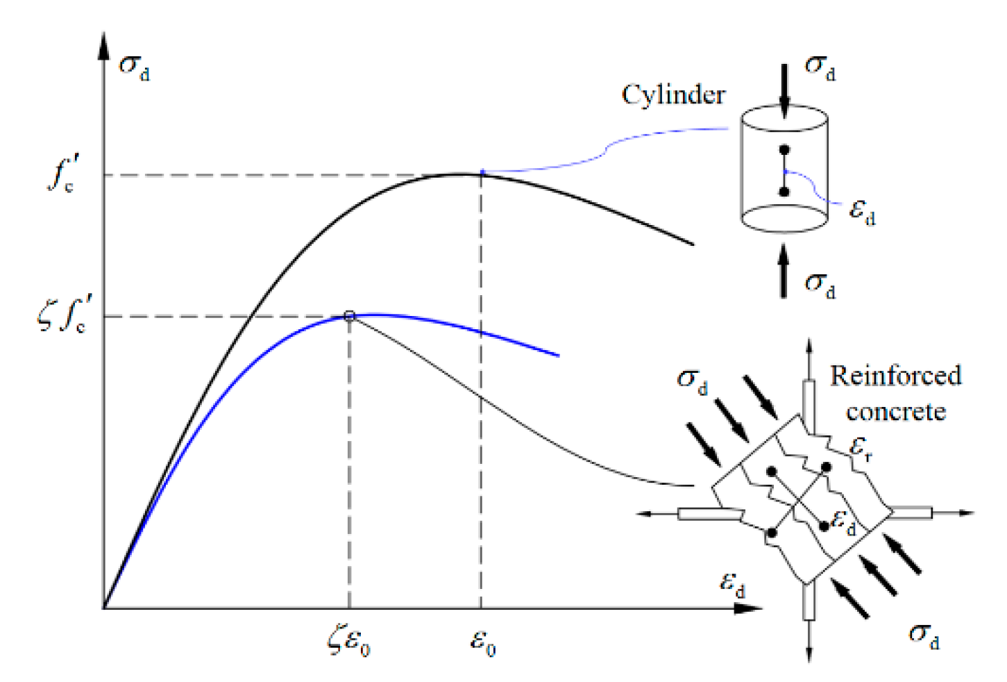
- The constitutive relation of the concrete proposed by Zhang and Hsu [35] is adopted, and it can be expressed as Equation (1).
4.2. P–Δ Skeleton Curves
4.2.1. Yield-Bearing Capacity and Displacement
4.2.2. Peak Bearing Capacity and Displacement
4.2.3. Ultimate Bearing Capacity and Displacement
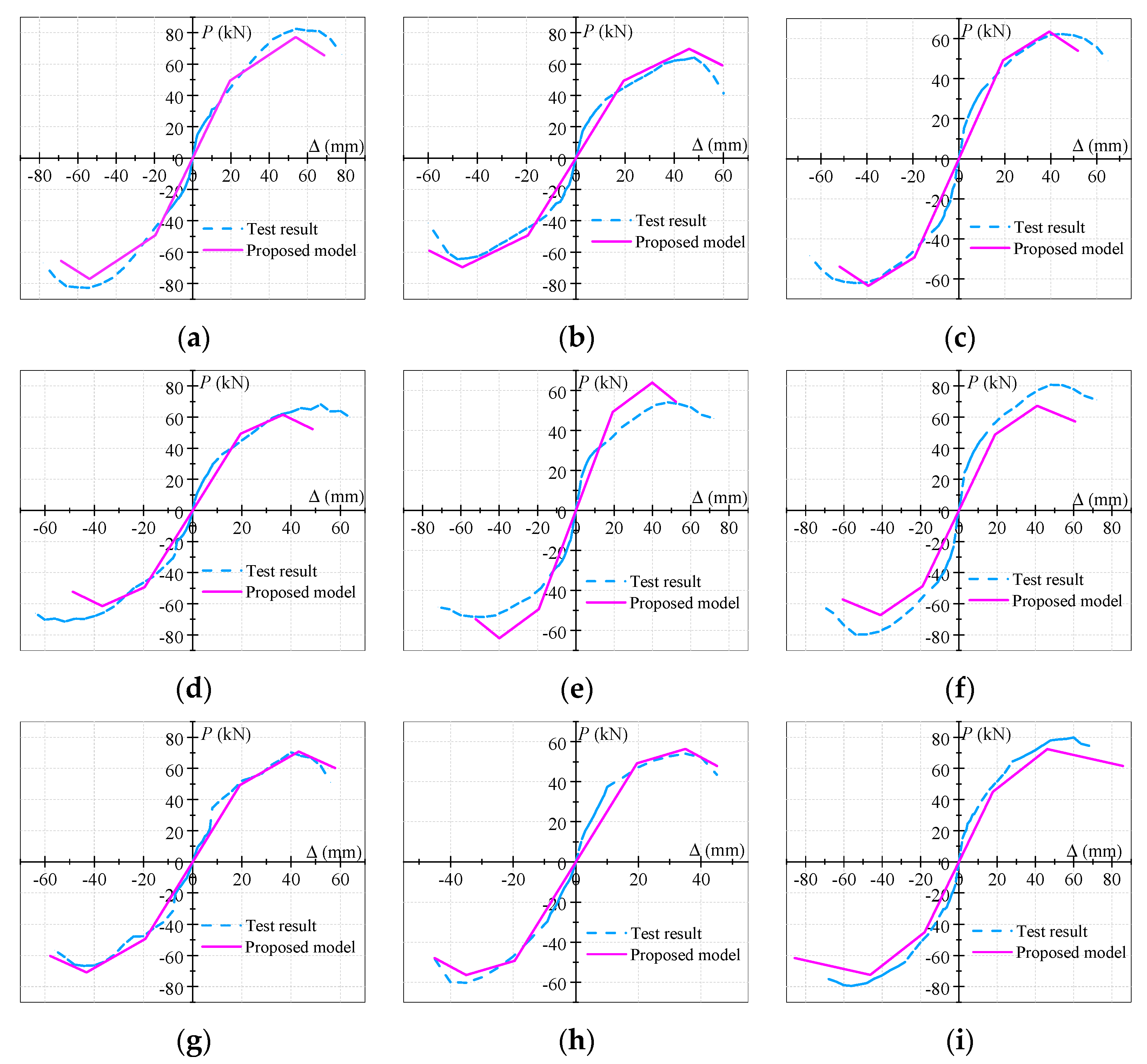
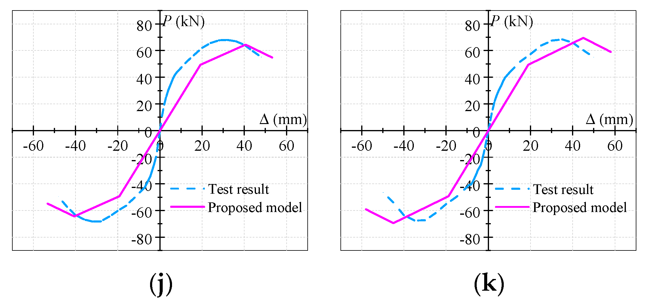
4.2.4. Evaluation of the Proposed Model of Skeleton Curve
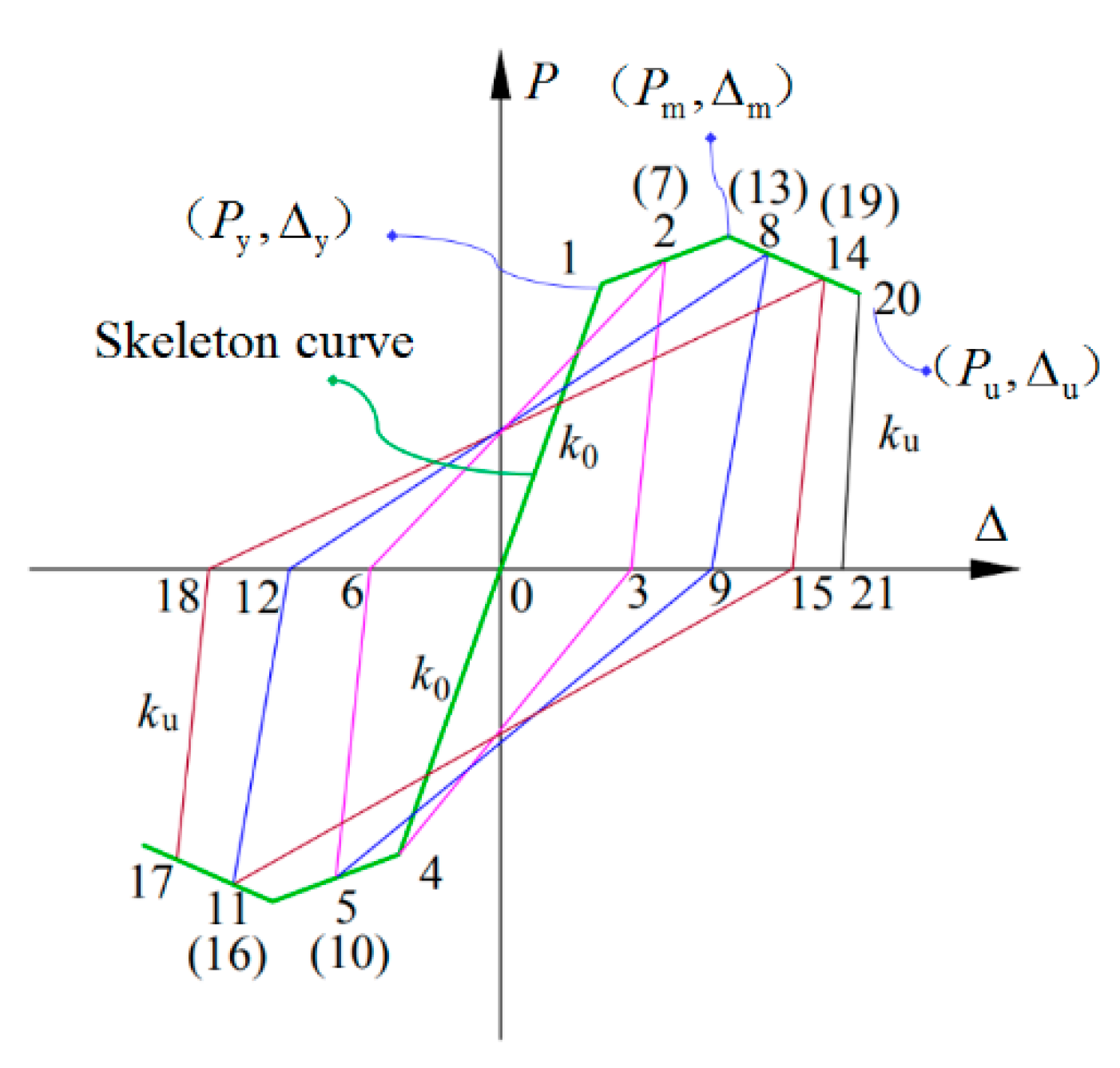
4.3. Hysteresis Rules
- (a)
- Before the specimens yielded, the skeleton curve was loaded and unloaded in the positive and negative directions with elastic stiffness , as shown in Figure 11 (Point 0→1);
- (b)
- After the specimens yielded, the skeleton curve was loaded in the positive direction (Point 1→2) and then unloaded from the displacement-amplitude point (Point 2) to point (Point 3), with the calculated unloading stiffness ;
- (c)
- When the reverse loading reached the yield load, the point of forward unloading (Point 3) pointed to the reverse yield point of the skeleton curve (Point 4). The reverse loading and unloading stiffness were the same as the forward loading and unloading stiffness (i.e., Point 4→5 and Point 5→6). Subsequently, the point of the reverse unloading (Point 6) pointed to the forward unloading point of the skeleton curve (Point 7). The duplicate process was followed based on the aforementioned rules. As shown in Figure 11, the traveling route of the model was determined according to the number, from small to large.
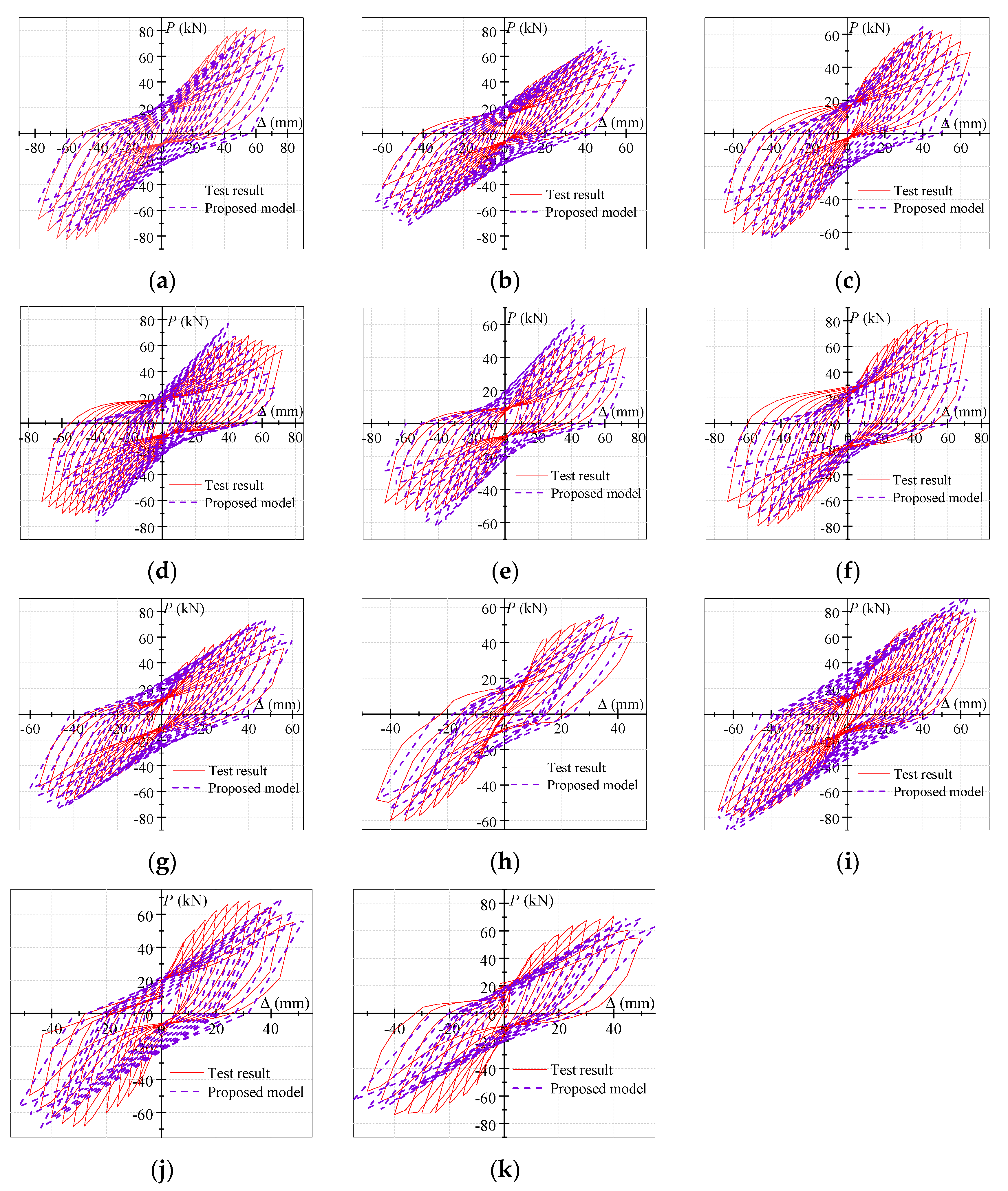
4.4. Verification of the Proposed Model of Hysteresis Curves
5. Conclusions
- (1)
- Three failure modes of the exterior PCRB joints (i.e., the failure of the frame beam, the failure of the junction of the frame beam and the ring beam, and the shear failure of the ring-beam joint) were observed during the tests. The reinforcement ratio of the frame beam obviously affected the failure modes of the exterior PCRB joints.
- (2)
- With the increase in the ring-beam-reinforcement ratio, the axial compression ratio, and the ring-beam width, the pinching effect of the hysteresis curves decreased, and the slope of the descending-stage skeleton curve decreased, whereas the frame-beam-reinforcement ratio and the CFRP-strip spacing had no distinct impact on the hysteresis curves, nor on the skeleton curves.
- (3)
- Based on the softening constitutive relation of the concrete, a simplified tri-linear-relation model for predicting the skeleton curves of exterior PCRB joints was proposed, considering the effects of the reinforcement ratio of the ring beam, the axial compression ratio, the ring-beam width, and the reinforcement ratio of the frame beam. The predicted theoretical curves agreed well with the test data.
- (4)
- On the basis of the Clough bi-linear degradation model, the loading and unloading rules of the exterior PCRB joints under low cyclic loading were determined by the analysis of the skeleton curves and the regression analysis of the experimental data. Subsequently, a model for estimating the hysteresis curves of exterior PCRB joints was established using the skeleton-curve-prediction model and the hysteresis rules. The established model of the hysteresis curves has acceptable accuracy.
- (5)
- Although further research is needed, the proposed force–displacement hysteresis model is considered by the authors to be a useful tool for evaluating the hysteresis behavior of exterior PCRB joints under low cyclic loading.
Author Contributions
Funding
Institutional Review Board Statement
Data Availability Statement
Conflicts of Interest
References
- Esmaeeli, E.; Danesh, F.; Tee, K.F.; Eshghi, S. A combination of gfrp sheets and steel cage for seismic strengthening of shear-deficient corner RC beam-column joints. Compos. Struct. 2016, 159, 206–219. [Google Scholar] [CrossRef]
- Forquin, P.; Chen, W. An experimental investigation of the progressive collapse resistance of beam-column RC sub-assemblages. Constr. Build. Mater. 2017, 152, 1068–1084. [Google Scholar] [CrossRef]
- Jin, L.; Miao, L.Y.; Han, J.Y.; Wei, N.; Dong, L. Size effect tests on shear failure of interior RC beam-to-column joints under monotonic and cyclic loadings. Eng. Struct. 2018, 175, 591–604. [Google Scholar] [CrossRef]
- Hanson, N.W.; Conner, H.W. Seismic resistance of reinforced concrete beam-column joints. J. Struct. Div. 1967, 93, 533–560. [Google Scholar] [CrossRef]
- Paulay, T.; Park, R.; Preistley, M. Reinforced concrete beam-column joints under seismic actions. ACI Struct. J. 1978, 75, 585–593. [Google Scholar]
- Realfonzo, R.; Napoli, A.; Pinilla, J. Cyclic behavior of RC beam-column joints strengthened with FRP systems. Constr. Build. Mater. 2014, 54, 282–297. [Google Scholar] [CrossRef]
- Alavi-Dehkordi, S.; Mostofinejad, D.; Alaee, P. Effects of high-strength reinforcing bars and concrete on seismic behavior of RC beam-column joints. Eng. Struct. 2019, 183, 702–719. [Google Scholar] [CrossRef]
- Wang, B.; Guan, S.Y.; Zhang, Y.; Bai, Y.T. Experimental behavior and failure modes of hybrid beam-to-column connections with RC wing-walls in industrial construction. Constr. Build. Mater. 2019, 218, 628–643. [Google Scholar] [CrossRef]
- Massone, L.M.; Orrego, G.N. Analytical model for shear strength estimation of reinforced concrete beam-column joints. Eng. Struct. 2018, 173, 681–692. [Google Scholar] [CrossRef]
- Wang, X.; Liu, J.; Zhang, S. Behavior of short circular tubed-reinforced-concrete columns subjected to eccentric compression. Eng. Struct. 2015, 105, 77–86. [Google Scholar] [CrossRef]
- Qiao, Q.Y.; Zhang, W.W.; Mou, B.; Gao, W.L. Seismic behavior of exposed concrete filled steel tube column bases with embedded reinforcing bars: Experimental investigation. Thin-Walled Struct. 2019, 136, 367–381. [Google Scholar] [CrossRef]
- Patel, V.I.; Hassanein, M.F.; Thai, H.T.; Abadi, H.A.; Elchalakani, M.; Bai, Y. Ultra-high strength circular short CFST columns: Axisymmetric analysis, behavior and design. Eng. Struct. 2019, 179, 268–283. [Google Scholar] [CrossRef]
- Gao, S.; Peng, Z.; Li, X.D.; Chen, D. Tests on axial strength of circle CFST stub columns under marine atmosphere in cold region. Constr. Build. Mater. 2020, 230, 117073. [Google Scholar] [CrossRef]
- Han, L.H.; Li, W. Seismic performance of CFST column to steel beam joint with RC slab: Experiments. J. Constr. Steel Res. 2010, 66, 1374–1386. [Google Scholar] [CrossRef]
- Li, W.; Han, L.H. Seismic performance of CFST column to steel beam joints with RC slab: Analysis. J. Constr. Steel Res. 2011, 67, 127–139. [Google Scholar] [CrossRef]
- Li, W.; Han, L.H. Seismic performance of CFST column to steel beam joint with RC slab: Joint model. J. Constr. Steel Res. 2012, 73, 66–79. [Google Scholar] [CrossRef]
- Ma, D.Y.; Han, L.H.; Zhao, X.L. Seismic performance of the concrete-encased CFST column to RC beam joint: Experiment. J. Constr. Steel Res. 2019, 154, 134–148. [Google Scholar] [CrossRef]
- Xu, L.; Pan, J.L.; Cai, J.M.; Wu, D.; Li, Y. Mechanical behavior of flat CFST column to steel beam joints under reversed cyclic loading. Eng. Struct. 2019, 198, 109540. [Google Scholar] [CrossRef]
- Fang, X.D.; Li, S.Y.; Chen, A.J. Experimental research on a new type of steel tube confined concrete column joint. J. Build. Struct. 1999, 20, 2–13. (In Chinese) [Google Scholar]
- Chen, Q.J.; Cai, J.; Bradford, M.A.; Zuo, Z.L. Seismic behaviour of a through-beam connection between concrete-filled steel tubular columns and reinforced concrete beams. Eng. Struct. 2014, 80, 24–39. [Google Scholar] [CrossRef]
- Zhang, Y.F.; Zhao, J.H.; Cai, C.S. Seismic behavior of ring beam joints between concrete-filled twin steel tubes columns and reinforced concrete beams. Eng. Struct. 2012, 39, 1–10. [Google Scholar] [CrossRef]
- Toutanji, H.; Saafi, M. Durability studies on concrete columns encased in PVC–FRP composite tubes. Compos. Struct. 2001, 54, 27–35. [Google Scholar] [CrossRef]
- Yu, F.; Niu, D.T. Stress-strain model of PVC-FRP confined concrete column subjected to axial compression. Int. J. Phys. Sci. 2015, 5, 2304–2309. [Google Scholar]
- Fakharifar, M.; Chen, G.D. Compressive behavior of FRP-confined concrete-filled PVC tubular columns. Compos. Struct. 2016, 141, 91–109. [Google Scholar] [CrossRef]
- Fakharifar, M.; Chen, G.D. FRP-confined concrete filled PVC tubes: A new design concept for ductile column construction in seismic regions. Constr. Build. Mater. 2017, 130, 1–10. [Google Scholar] [CrossRef]
- Yu, F.; Xu, G.S.; Niu, D.T.; Cheng, A.C.; Wu, P.; Kong, Z.Y. Experimental study on PVC-CFRP confined concrete columns under low cyclic loading. Constr. Build. Mater. 2018, 177, 287–302. [Google Scholar] [CrossRef]
- Fang, Y.; Yu, F.; Cheng, A.C.; Wang, S.L.; Xu, G.S. An analytical model for PVC-FRP confined reinforced concrete columns under low cyclic loading. Struct. Eng. Mech. 2021, 77, 179–196. [Google Scholar]
- Gao, C.; Huang, L.; Yan, L.B.; Jin, R.Y.; Kasal, B. Strength and ductility improvement of recycled aggregate concrete by polyester FRP-PVC tube confinement. Compos. Part B Eng. 2019, 162, 178–197. [Google Scholar] [CrossRef]
- Fang, Y.; Yu, F.; Guan, Y.C.; Wang, Z.W. A model for predicting the stress-strain relation of PVC-CFRP confined concrete stub columns under axial compression. Structures 2020, 26, 259–270. [Google Scholar] [CrossRef]
- Yu, F.; Li, D.A.; Niu, D.T.; Zhu, D.F.; Kong, Z.Y.; Zhang, N.N.; Fang, Y. A model for ultimate bearing capacity of PVC-CFRP confined concrete column with reinforced concrete beam joint under axial compression. Constr. Build. Mater. 2019, 214, 668–676. [Google Scholar] [CrossRef]
- Yu, F.; Zhang, N.N.; Niu, D.T.; Kong, Z.Y.; Zhu, D.F.; Wang, S.L.; Fang, Y. Strain analysis of PVC-CFRP confined concrete column with ring beam joint under axial compression. Compos. Struct. 2019, 224, 111012. [Google Scholar] [CrossRef]
- Yu, F.; Song, Z.K.; Mansouri, I.; Liu, J.; Fang, Y. Experimental study and finite element analysis of PVC-CFRP confined concrete column- ring beam joint subjected to eccentric compression. Constr. Build. Mater. 2020, 254, 119081. [Google Scholar] [CrossRef]
- JGJ/T101-2015; Specification for Seismic Test of Buildings, Beijing, National Standards of People’s Republic of China. China Academy of Building Research: Beijing, China, 2015.
- Vaiana, N.; Capuano, R.; Rosati, L. Evaluation of path-dependent work and internal energy change for hysteretic mechanical systems. Mech. Syst. Signal Process. 2023, 186, 109862. [Google Scholar] [CrossRef]
- Zhang, L.X.B.; Hsu, T.T.C. Behavior and analysis of 100 MPa concrete membrane elements. J. Struct. Eng. ASCE 1998, 124, 24–34. [Google Scholar] [CrossRef]
- Foster, S.J.; Gilbert, R.I. Design of nonflexural members with normal and high-strength concretes. ACI Struct. J. 1996, 96, 3–10. [Google Scholar]
- Panagiotakos, T.B.; Fardis, M.N. Deformations of reinforced concrete members at yielding and ultimate. ACI Struct. J. 2001, 98, 135–148. [Google Scholar]
- Li, Z.L. Study on Seismic Behavior of PVC-CFRP Confined Concrete Column-Reinforced Concrete Ring Beam T-Joint. Master’s Thesis, Anhui University of Technology, Ma’anshan, China, 2020. [Google Scholar]
- Clough, R.W. Effect of stiffness degradation on earthquake ductility requirements. In Proceedings of the Japan Earthquake Engineering Symposium; Department of Civil Engineering, University of California: Berkeley, CA, USA, 1966. [Google Scholar]
- Capuano, R.; Vaiana, N.; Pellecchia, D.; Rosati, L. A solution algorithm for a modified Bouc-Wen model capable of simulating cyclic softening and pinching phenomena. IFAC-Pap. Line 2022, 55, 319–324. [Google Scholar] [CrossRef]
- Vaiana, N.; Rosati, L. Classification and unified phenomenological modeling of complex uniaxial rate-independent hysteretic responses. Mech. Syst. Signal Process. 2023, 182, 109539. [Google Scholar] [CrossRef]





| Specimen | Ring Beam b × h (mm) | (mm) | Axial Compression Ratio n | ||
|---|---|---|---|---|---|
| S1 | 100 × 340 | 40 | 1.51% (4A10 + 4A8) | 2.17% (4C20) | 0.2 |
| S2 | 100 × 340 | 40 | 1.27% (4A8 + 4A8) | 2.17% (4C20) | 0.2 |
| S3 | 100 × 340 | 40 | 0.98% (4A8 + 4A6.5) | 2.17% (4C20) | 0.2 |
| S4 | 100 × 340 | 20 | 0.98% (4A8 + 4A6.5) | 2.17% (4C20) | 0.2 |
| S5 | 100 × 340 | 60 | 0.98% (4A8 + 4A6.5) | 2.17% (4C20) | 0.2 |
| S6 | 100 × 340 | 40 | 1.51% (4A10 + 4A8) | 1.76% (3C18) | 0.2 |
| S7 | 125 × 340 | 40 | 1.05% (4A10 + 4A6.5) | 2.17% (4C20) | 0.2 |
| S8 | 75 × 340 | 40 | 1.04% (4A6.5 + 4A6.5) | 2.17% (4C20) | 0.2 |
| S9 | 100 × 340 | 40 | 1.51% (4A10 + 4A8) | 1.39% (3C16) | 0.2 |
| S10 | 100 × 340 | - | 0.98% (4A8 + 4A6.5) | 2.17% (4C20) | 0.2 |
| S11 | 100 × 340 | 40 | 0.98% (4A8 + 4A6.5) | 2.17% (4C20) | 0.4 |
| Materials | Yield Strength (MPa) | Ultimate Strength (MPa) | Elastic Modulus (MPa) |
|---|---|---|---|
| CFRP (Tension) | - | 3796 | 274,000 |
| PVC (Tension) | - | 69.6 | 2590 |
| Concrete (Compression) | - | 22.9 | 31,200 |
| Reinforcement (Tension) A6.5 | 323 | 542 | 197,000 |
| Reinforcement (Tension) A8 | 308 | 426 | 201,000 |
| Reinforcement (Tension) A10 | 313 | 432 | 197,000 |
| Reinforcement (Tension) C16 | 451 | 620 | 195,000 |
| Reinforcement (Tension) C18 | 465 | 633 | 195,000 |
| Reinforcement (Tension) C20 | 446 | 611 | 199,000 |
| Specimen | (kN) | (mm) | (kN) | (mm) | ||||||
|---|---|---|---|---|---|---|---|---|---|---|
| Equation (11) | Equation (17) | Equation (4) | Equation (18) | Equation (11) | Equation (17) | Equation (4) | Equation (18) | |||
| S1 | 57.5 | 25.1 | 92.1 | 49.3 | 11.7 | 19.5 | 0.624 | 1.166 | 2.145 | 1.287 |
| S2 | 45.8 | 20.4 | 92.1 | 49.3 | 11.9 | 19.4 | 0.497 | 0.929 | 1.714 | 1.052 |
| S3 | 51.4 | 24.3 | 92.1 | 49.3 | 12.2 | 19.3 | 0.558 | 1.043 | 1.992 | 1.259 |
| S4 | 47.7 | 21.9 | 92.1 | 49.3 | 12.3 | 19.5 | 0.518 | 0.968 | 1.780 | 1.123 |
| S5 | 40.5 | 22.4 | 92.1 | 49.3 | 12.2 | 19.3 | 0.440 | 0.822 | 1.836 | 1.161 |
| S6 | 53.5 | 19.3 | 75.5 | 48.8 | 12.0 | 18.9 | 0.709 | 1.096 | 1.608 | 1.021 |
| S7 | 49.0 | 18.6 | 92.1 | 49.3 | 12.1 | 19.2 | 0.532 | 0.994 | 1.537 | 0.969 |
| S8 | 44.6 | 17.3 | 92.1 | 49.3 | 12.4 | 19.5 | 0.484 | 0.905 | 1.395 | 0.887 |
| S9 | 50.5 | 20.9 | 60.4 | 45.1 | 11.3 | 17.8 | 0.836 | 1.120 | 1.850 | 1.174 |
| S10 | 49.9 | 11.5 | 92.1 | 49.3 | 12.1 | 19.2 | 0.542 | 1.012 | 0.950 | 0.599 |
| S11 | 53.6 | 16.1 | 92.1 | 49.3 | 11.9 | 18.9 | 0.582 | 1.087 | 1.353 | 0.852 |
| Average value | - | - | - | - | - | - | 0.575 | 1.013 | 1.651 | 1.035 |
| Standard deviation | - | - | - | - | - | - | 0.113 | 0.103 | 0.334 | 0.202 |
| Specimen | Yield Point | Peak Point | Ultimate Point | |||||||||
|---|---|---|---|---|---|---|---|---|---|---|---|---|
| S1 | 57.5 | 25.1 | 49.3 | 19.5 | 82.5 | 54.0 | 77.2 | 53.9 | 70.5 | 75.5 | 65.6 | 68.7 |
| S2 | 45.8 | 20.4 | 49.3 | 19.4 | 64.1 | 48.1 | 69.7 | 46.1 | 54.6 | 54.8 | 59.2 | 59.5 |
| S3 | 51.4 | 24.3 | 49.3 | 19.3 | 62.3 | 45.0 | 63.5 | 39.4 | 49.7 | 64.2 | 54.0 | 51.8 |
| S4 | 47.7 | 21.9 | 49.3 | 19.5 | 68.1 | 52.1 | 61.5 | 36.7 | 59.9 | 63.9 | 52.3 | 48.7 |
| S5 | 40.5 | 22.4 | 49.3 | 19.3 | 54.0 | 48.1 | 63.9 | 39.9 | 46.0 | 72.1 | 54.3 | 52.3 |
| S6 | 53.5 | 19.3 | 48.8 | 18.9 | 80.8 | 48.0 | 67.3 | 40.9 | 72.1 | 71.1 | 57.2 | 60.7 |
| S7 | 49.0 | 18.6 | 49.3 | 19.2 | 70.4 | 40.0 | 70.9 | 43.1 | 59.7 | 53.0 | 60.3 | 57.9 |
| S8 | 44.6 | 17.3 | 49.3 | 19.5 | 54.1 | 35.0 | 56.4 | 35.0 | 45.9 | 43.8 | 47.9 | 45.1 |
| S9 | 50.5 | 20.9 | 45.1 | 16.6 | 78.7 | 52.0 | 72.5 | 46.3 | 68.1 | 74.6 | 61.6 | 85.7 |
| S10 | 49.9 | 11.5 | 49.3 | 20.0 | 68.0 | 32.1 | 64.5 | 40.6 | 58.0 | 45.5 | 54.8 | 53.2 |
| S11 | 53.6 | 16.1 | 49.3 | 20.1 | 68.3 | 35.1 | 69.5 | 45.0 | 58.0 | 46.8 | 59.1 | 58.0 |
| Specimen | Variations in Unloading Stiffnesses of Specimens | ||||||||||||||
|---|---|---|---|---|---|---|---|---|---|---|---|---|---|---|---|
| S1 | 0.48 | 0.72 | 0.96 | 1.20 | 1.44 | 1.68 | 1.91 | 2.15 | 2.39 | 2.63 | 2.87 | 3.11 | - | - | |
| 1.62 | 1.58 | 1.53 | 1.39 | 1.31 | 1.25 | 1.18 | 1.17 | 1.11 | 1.09 | 1.04 | 0.99 | - | - | ||
| S2 | 0.39 | 0.59 | 0.79 | 0.98 | 1.18 | 1.37 | 1.57 | 1.77 | 1.96 | 2.16 | 2.36 | 2.55 | 2.75 | 2.94 | |
| 2.26 | 1.92 | 2.08 | 1.74 | 1.57 | 1.40 | 1.29 | 1.24 | 1.18 | 1.16 | 1.19 | 1.15 | 1.16 | 1.05 | ||
| S3 | 0.41 | 0.62 | 0.82 | 1.03 | 1.24 | 1.44 | 1.65 | 1.85 | 2.06 | 2.27 | 2.47 | 2.67 | - | - | |
| 3.40 | 2.57 | 2.10 | 1.81 | 1.68 | 1.50 | 1.40 | 1.37 | 1.33 | 1.36 | 1.31 | 1.33 | - | - | ||
| S4 | 0.37 | 0.55 | 0.73 | 0.91 | 1.28 | 1.46 | 1.65 | 1.82 | 2.01 | 2.19 | 2.38 | 2.55 | 2.74 | 2.92 | |
| 4.02 | 3.98 | 4.73 | 3.93 | 3.14 | 2.92 | 2.67 | 2.68 | 2.57 | 2.50 | 2.66 | 2.45 | 2.89 | 3.42 | ||
| S5 | 0.54 | 0.81 | 1.07 | 1.34 | 1.61 | 1.88 | 2.15 | 2.41 | 2.68 | 2.95 | 3.22 | - | - | - | |
| 2.30 | 1.73 | 1.51 | 1.36 | 1.39 | 1.30 | 1.29 | 1.23 | 1.16 | 1.11 | 1.06 | - | - | - | ||
| S6 | 0.62 | 0.93 | 1.24 | 1.56 | 1.87 | 2.18 | 2.49 | 2.80 | 3.10 | 3.41 | 3.74 | - | - | - | |
| 8.12 | 4.62 | 2.91 | 2.08 | 1.77 | 1.80 | 1.73 | 1.77 | 1.77 | 2.02 | 2.13 | - | - | - | ||
| S7 | 0.43 | 0.65 | 0.86 | 1.08 | 1.29 | 1.51 | 1.72 | 1.94 | 2.15 | 2.37 | 2.58 | 2.80 | 3.02 | - | |
| 2.63 | 2.23 | 1.96 | 2.17 | 1.87 | 1.57 | 1.44 | 1.33 | 1.27 | 1.15 | 1.11 | 1.05 | 0.88 | - | ||
| S8 | 0.58 | 0.87 | 1.16 | 1.45 | 1.74 | 2.02 | 2.32 | 2.60 | - | - | - | - | - | - | |
| 1.84 | 1.38 | 1.13 | 0.96 | 0.84 | 0.85 | 0.83 | 0.71 | - | - | - | - | - | - | ||
| S9 | 0.38 | 0.77 | 0.96 | 1.15 | 1.34 | 1.53 | 1.72 | 1.92 | 2.11 | 2.49 | 2.68 | 2.87 | 3.06 | 3.26 | |
| 3.03 | 2.59 | 4.43 | 3.20 | 2.68 | 2.20 | 1.90 | 1.73 | 1.57 | 1.39 | 1.28 | 1.26 | 1.24 | 1.16 | ||
| S10 | 0.70 | 1.05 | 1.39 | 1.74 | 2.09 | 2.44 | 2.79 | 3.14 | 3.49 | 3.83 | 4.18 | - | - | - | |
| 2.52 | 1.60 | 1.24 | 1.04 | 0.93 | 0.93 | 0.86 | 0.78 | 0.68 | 0.61 | 0.55 | - | - | - | ||
| S11 | 0.62 | 0.93 | 1.24 | 1.55 | 1.87 | 2.18 | 2.49 | 2.80 | 3.10 | - | - | - | - | - | |
| 2.40 | 1.84 | 1.35 | 1.17 | 1.04 | 0.96 | 1.00 | 1.06 | 0.89 | - | - | - | - | - | ||
Disclaimer/Publisher’s Note: The statements, opinions and data contained in all publications are solely those of the individual author(s) and contributor(s) and not of MDPI and/or the editor(s). MDPI and/or the editor(s) disclaim responsibility for any injury to people or property resulting from any ideas, methods, instructions or products referred to in the content. |
© 2023 by the authors. Licensee MDPI, Basel, Switzerland. This article is an open access article distributed under the terms and conditions of the Creative Commons Attribution (CC BY) license (https://creativecommons.org/licenses/by/4.0/).
Share and Cite
Wu, P.; Guan, Y.; Yu, F.; Li, Z.; Fang, Y. Force–Displacement Hysteresis Model of Exterior PCRB Joints under Low Cyclic Loading. Polymers 2023, 15, 2008. https://doi.org/10.3390/polym15092008
Wu P, Guan Y, Yu F, Li Z, Fang Y. Force–Displacement Hysteresis Model of Exterior PCRB Joints under Low Cyclic Loading. Polymers. 2023; 15(9):2008. https://doi.org/10.3390/polym15092008
Chicago/Turabian StyleWu, Ping, Yucong Guan, Feng Yu, Zilong Li, and Yuan Fang. 2023. "Force–Displacement Hysteresis Model of Exterior PCRB Joints under Low Cyclic Loading" Polymers 15, no. 9: 2008. https://doi.org/10.3390/polym15092008
APA StyleWu, P., Guan, Y., Yu, F., Li, Z., & Fang, Y. (2023). Force–Displacement Hysteresis Model of Exterior PCRB Joints under Low Cyclic Loading. Polymers, 15(9), 2008. https://doi.org/10.3390/polym15092008


