
Nanomaterials Reinforced Polymer Filament for Fused Deposition Modeling: A State-of-the-Art Review


Abstract
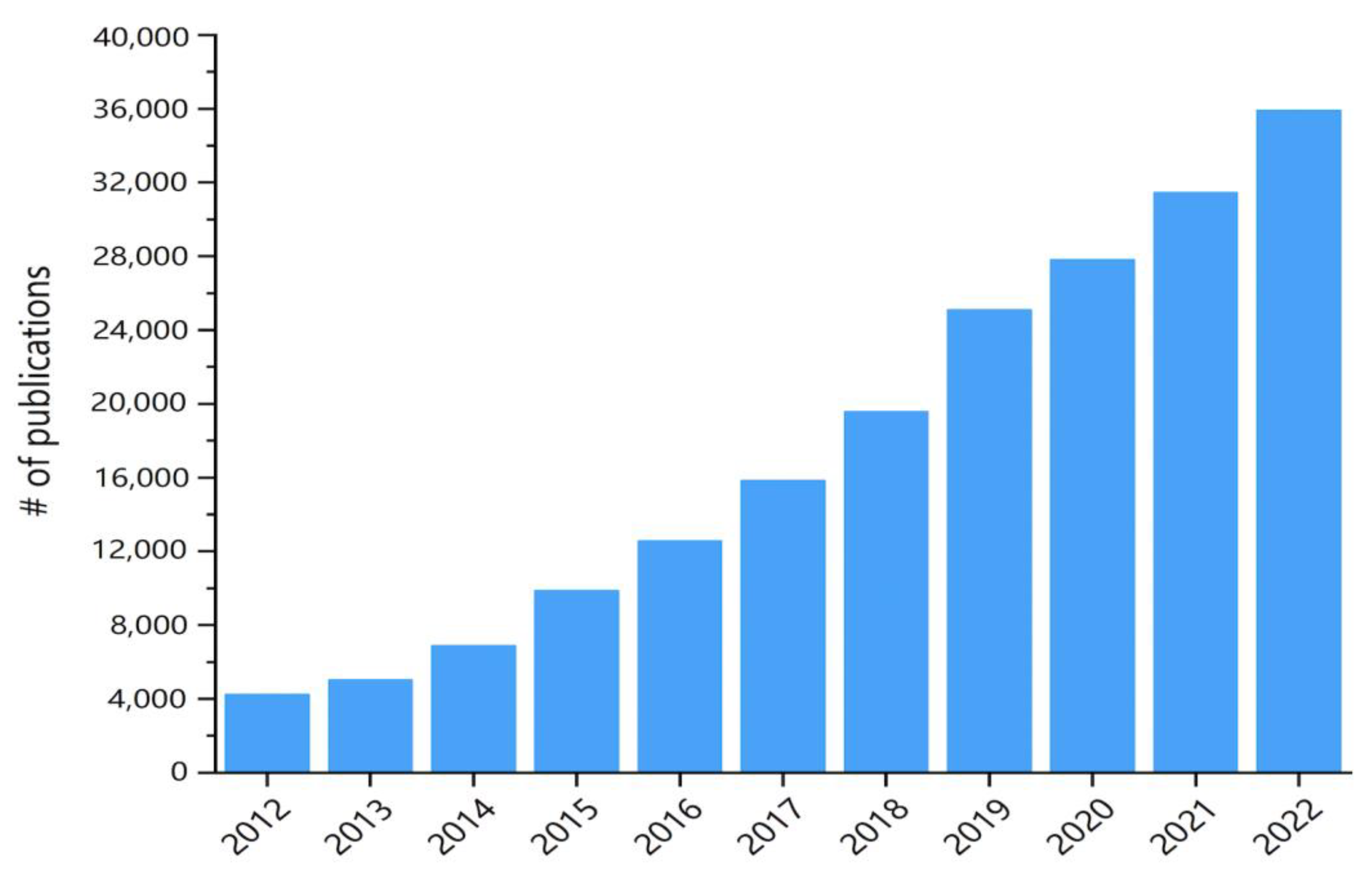
1. Introduction
2. Fused Deposition Modeling and the Filament Materials
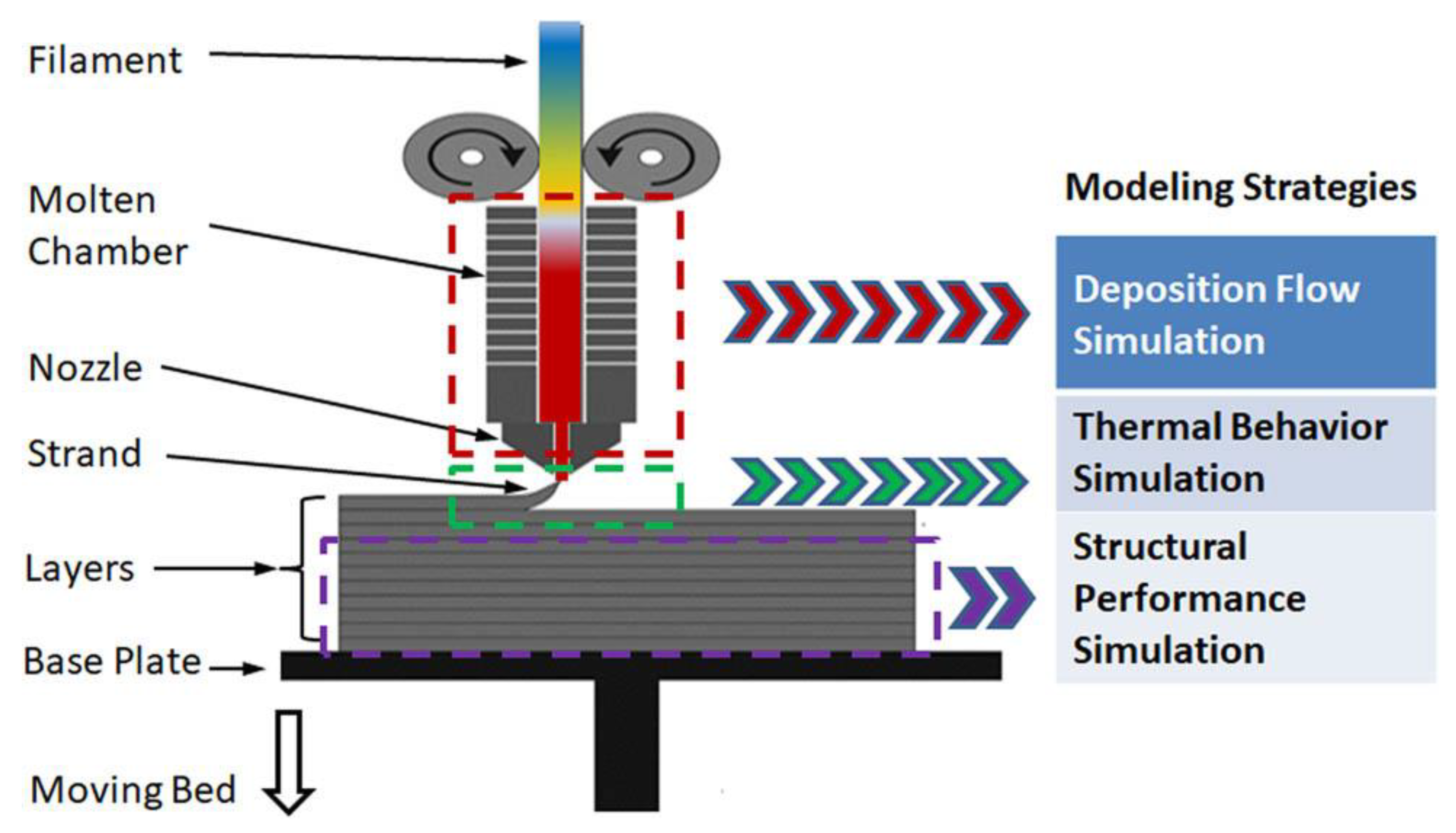
2.1. Introduction of Fused Deposition Modeling
- (1)
- Low maintenance cost and safe system operation due to the simple construction principle and easy manipulation of the hot melt extrusion system.
- (2)
- The forming speed is high, and the products produced by the fusion deposition method do not require the process of reworking scrapers as in SLA.
- (3)
- No chemical changes in the raw material during the forming process, so that the warpage and deformation of the parts are small.
- (4)
- High raw material utilization rate and rich material sources.
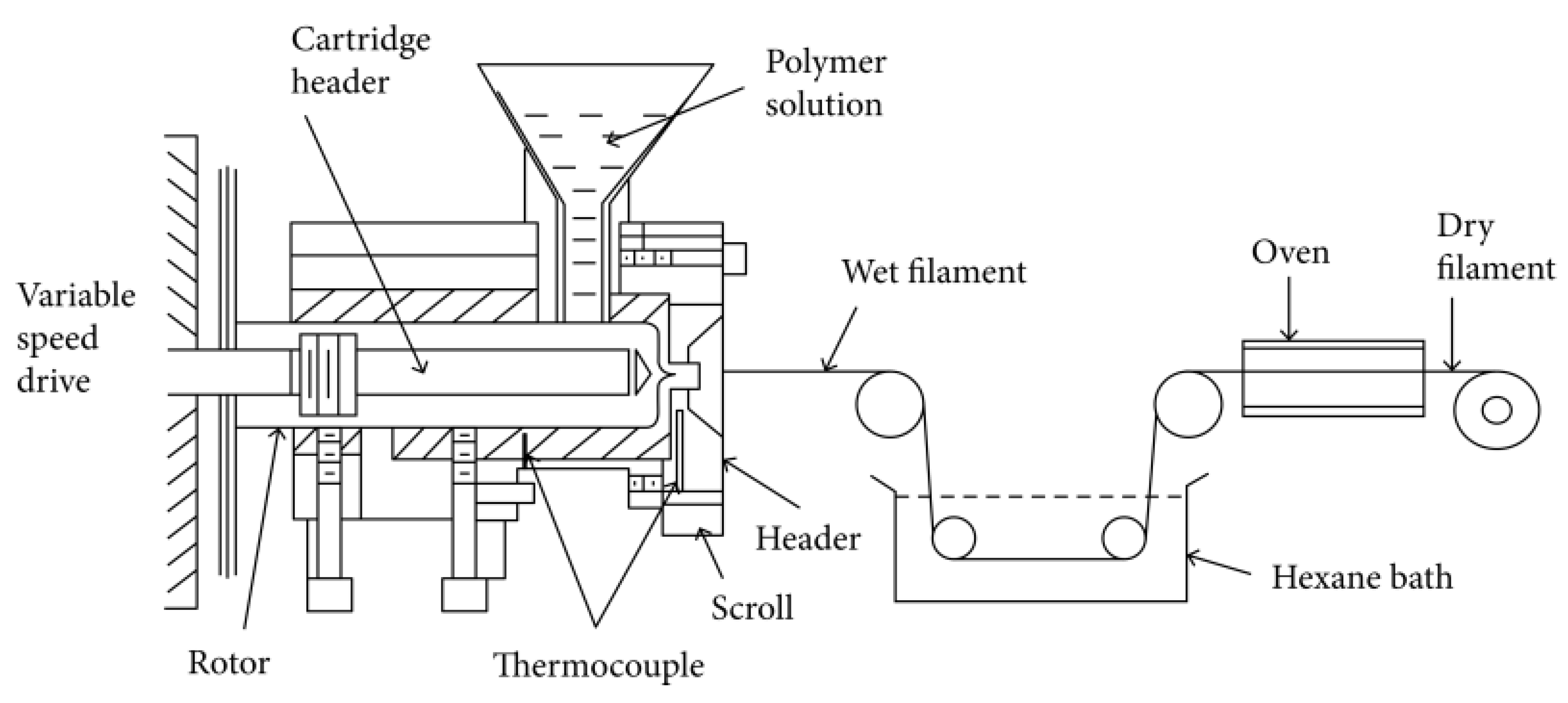
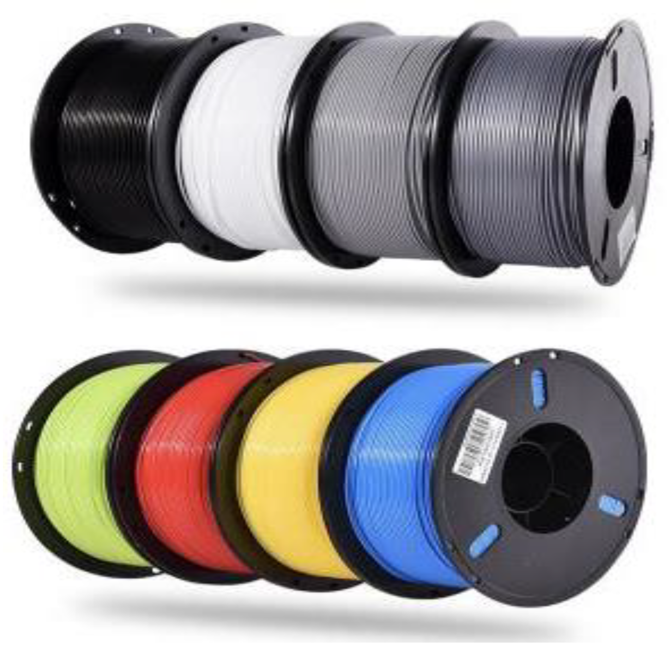
2.2. Preparation of Filament Materials
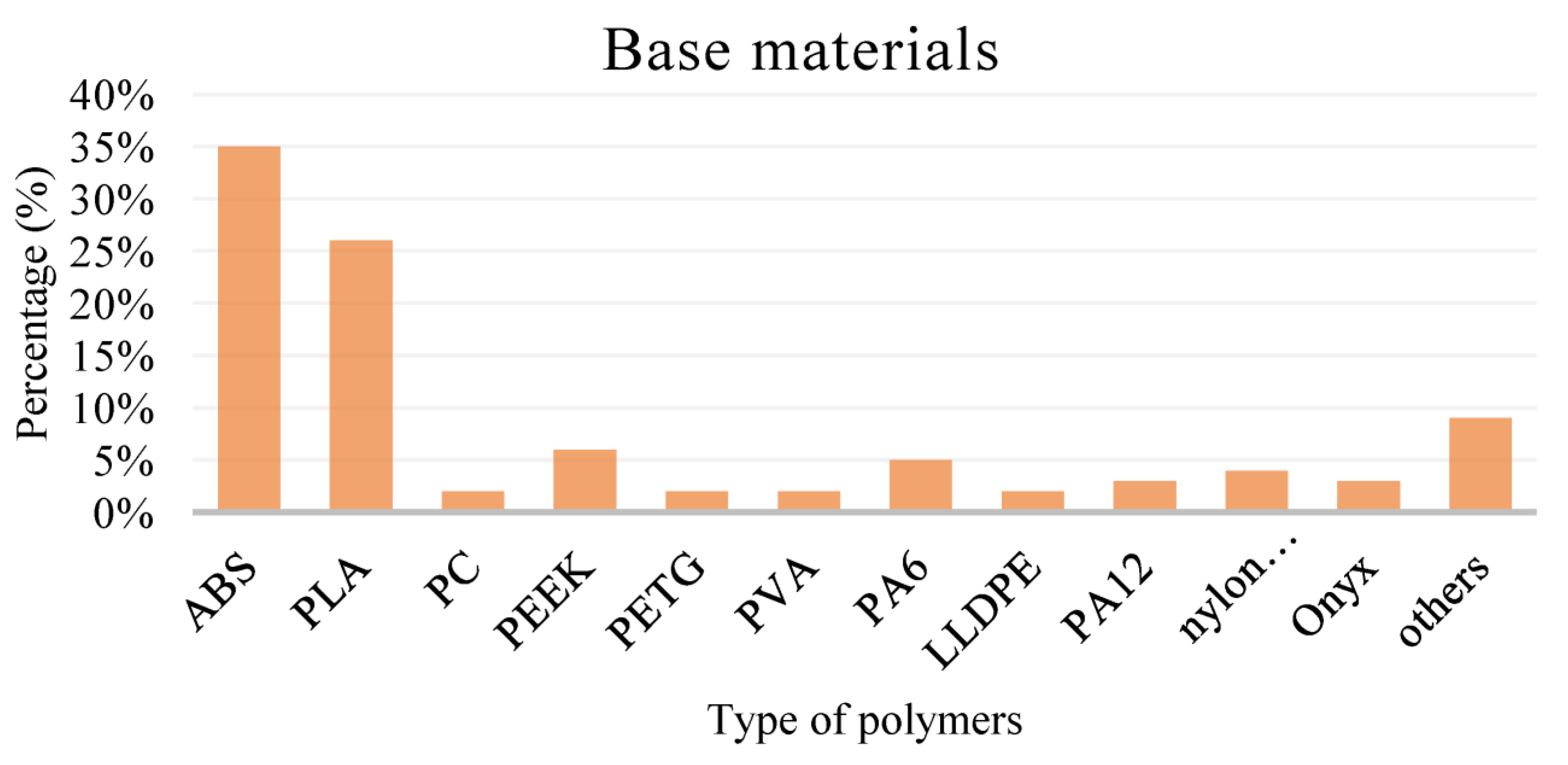
2.3. Materials for Fused Deposition Modeling
3. Polymer/Carbon Nanocomposites Based Modification and the Applications
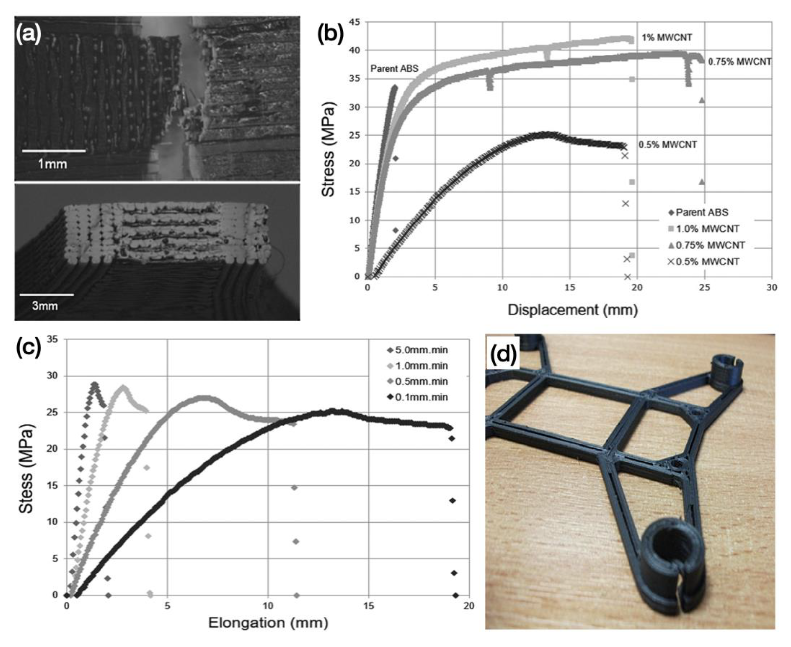
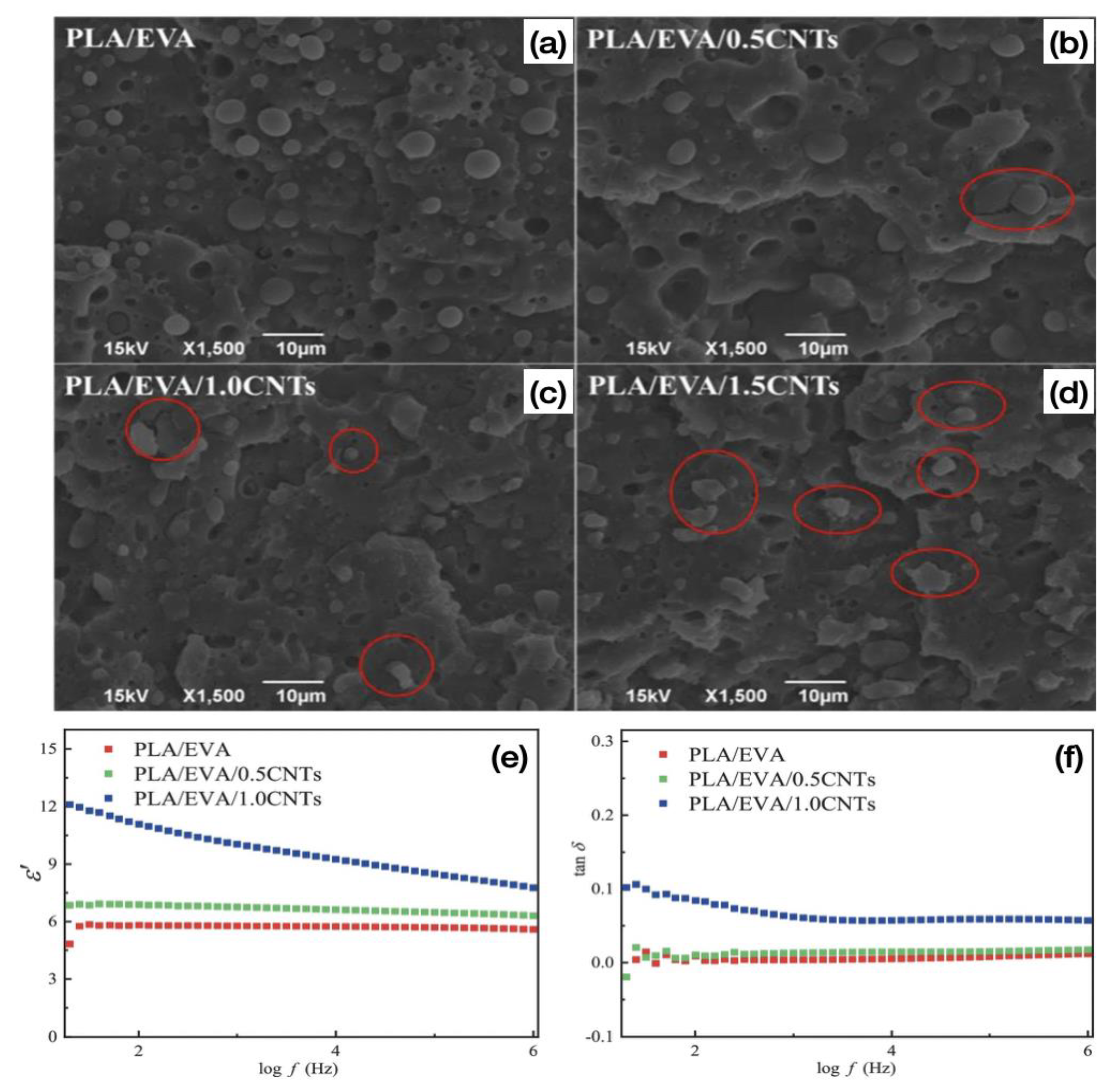
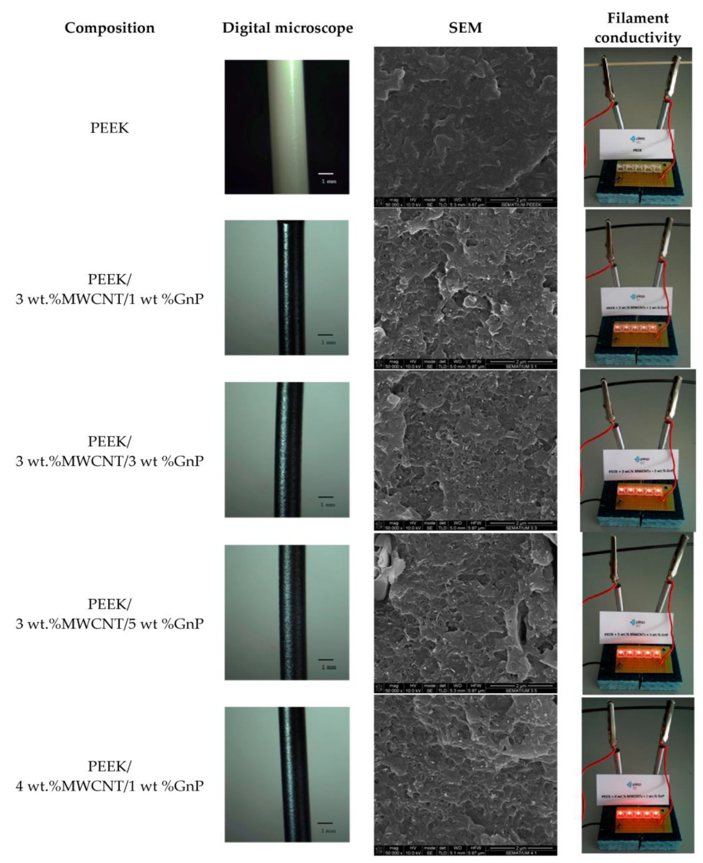
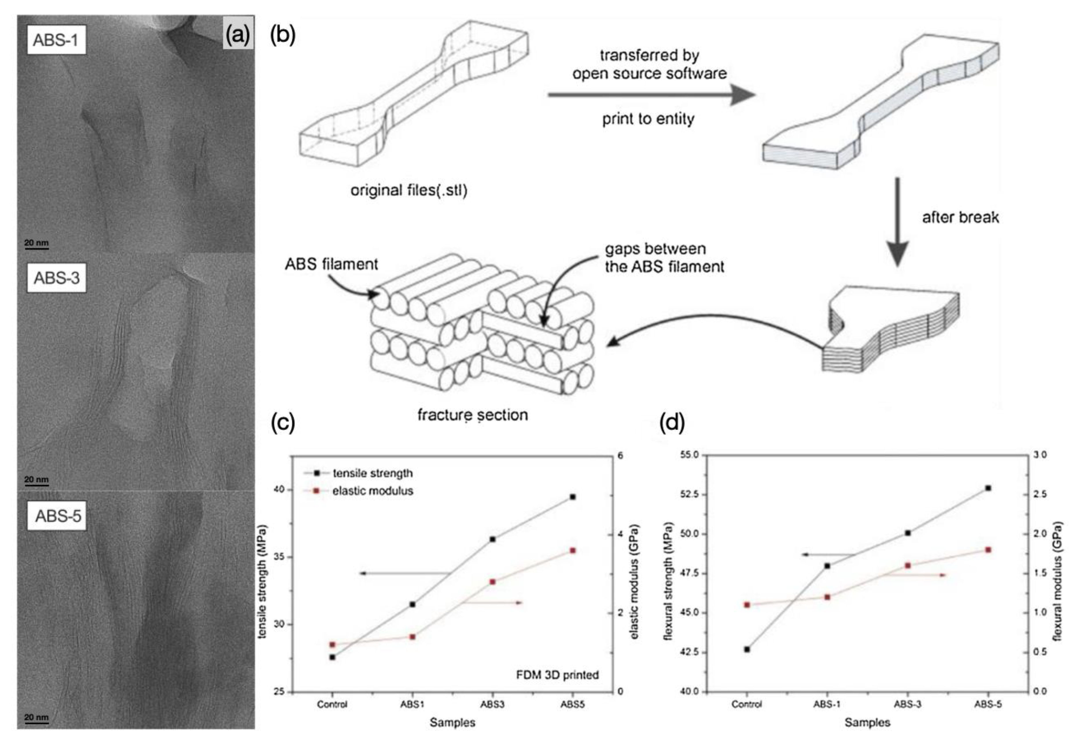
3.1. Polymer/CNT Nanocomposites Based Composite Filaments
3.2. Polymer/Nano Clay (NC) Based Composite Filaments
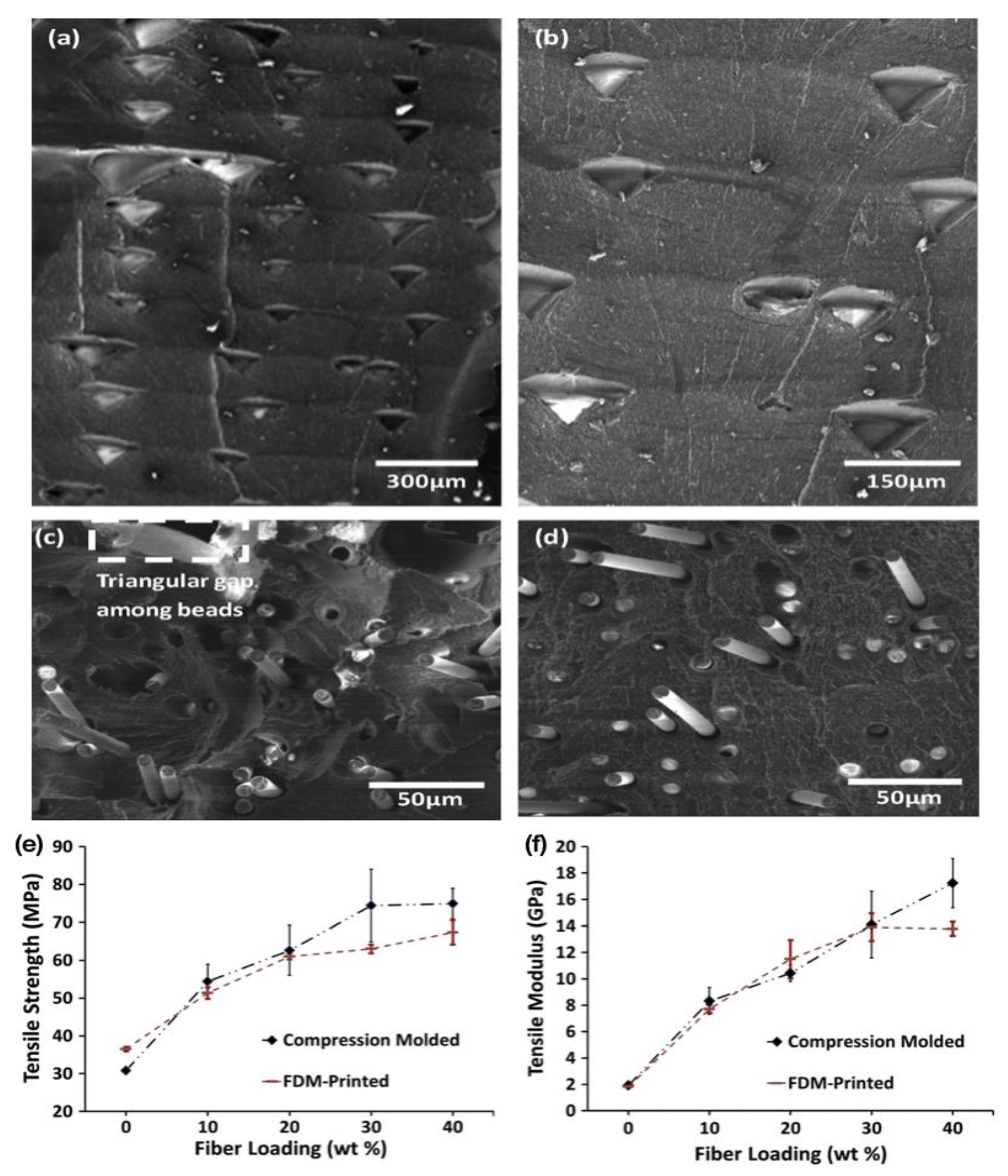
3.3. Polymer/Carbon Fiber (CF) Based Composite Filaments
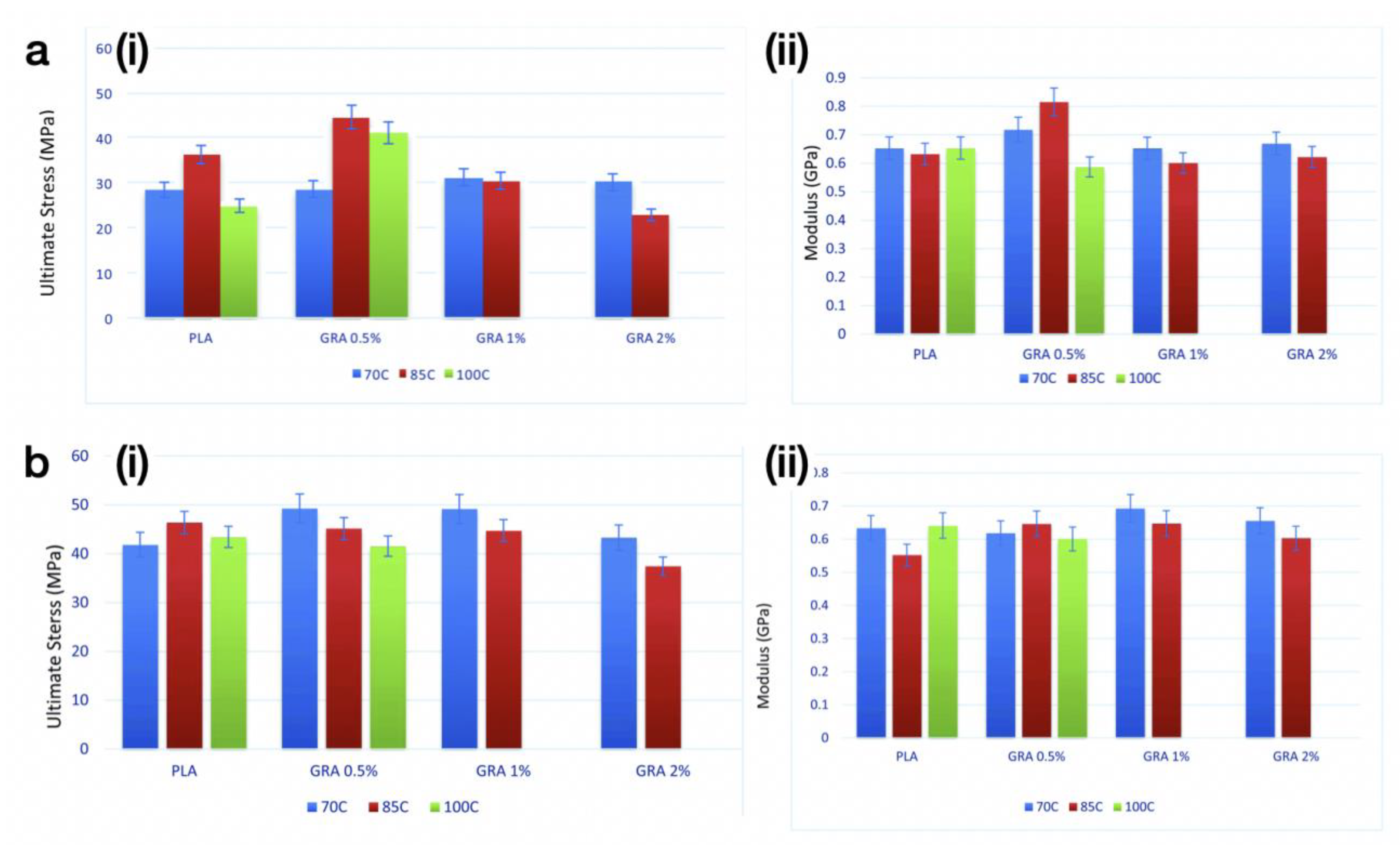
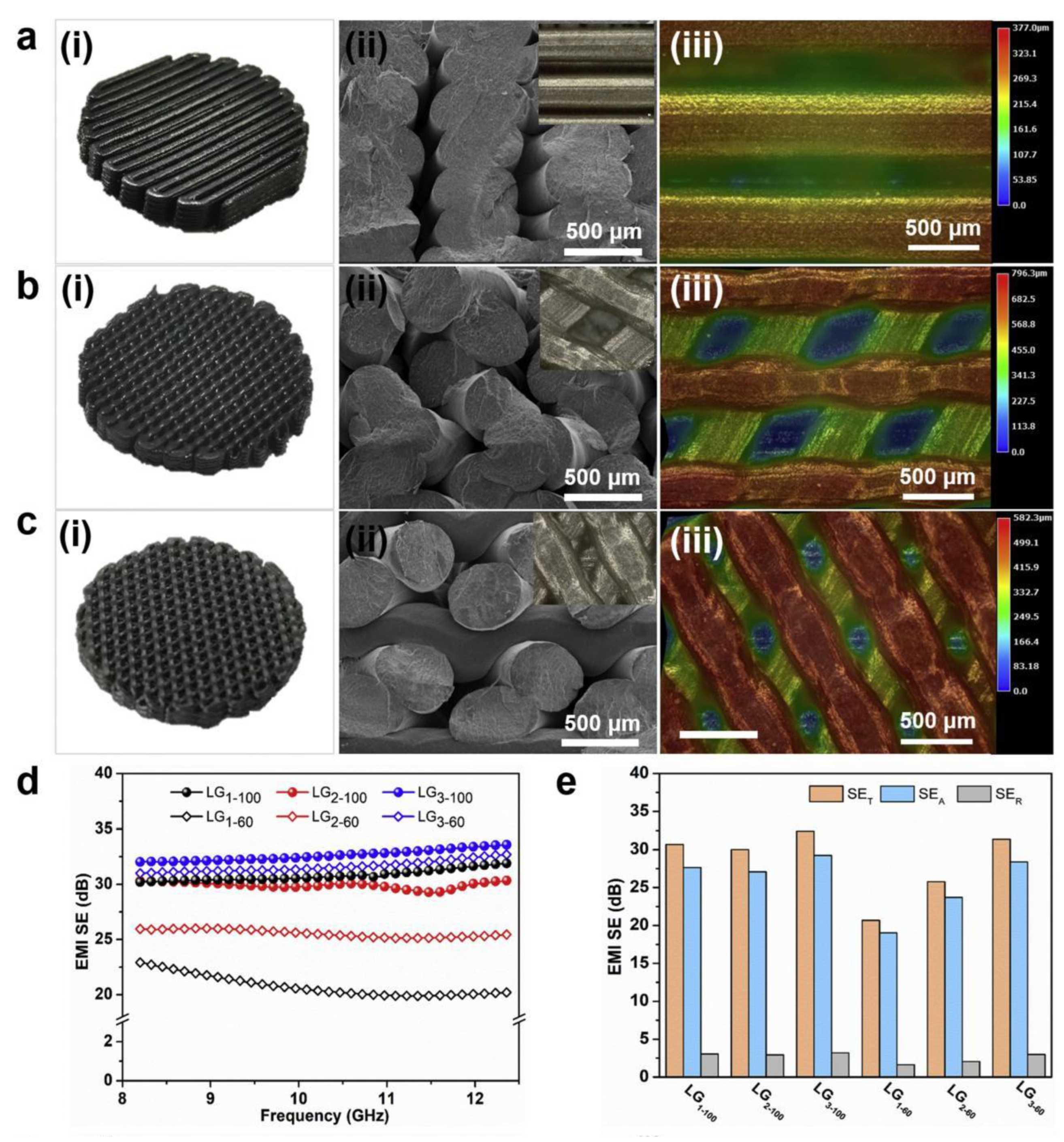
3.4. Polymer/Graphene Based Composite Filaments
4. Polymer/Metal Nanoparticles (MNPs) Based Composite Filaments
5. Polymer/Oxides Based Composite Filaments
6. Conclusions and Future Work
- Continue to expand the nanocomposite portfolio. Most of the current matrix materials for composites used in FDM are based on several polymer types such as ABS and PLA. Undocumented or novel polymers need to be explored with good compatibility with FDM 3D printing. In addition, the building of processing-structure-property relationships for polymer nanocomposites in the context of FDM will facilitate the discovery of lighter, stronger and multifunctional materials, further expanding the capabilities of additive manufacturing.
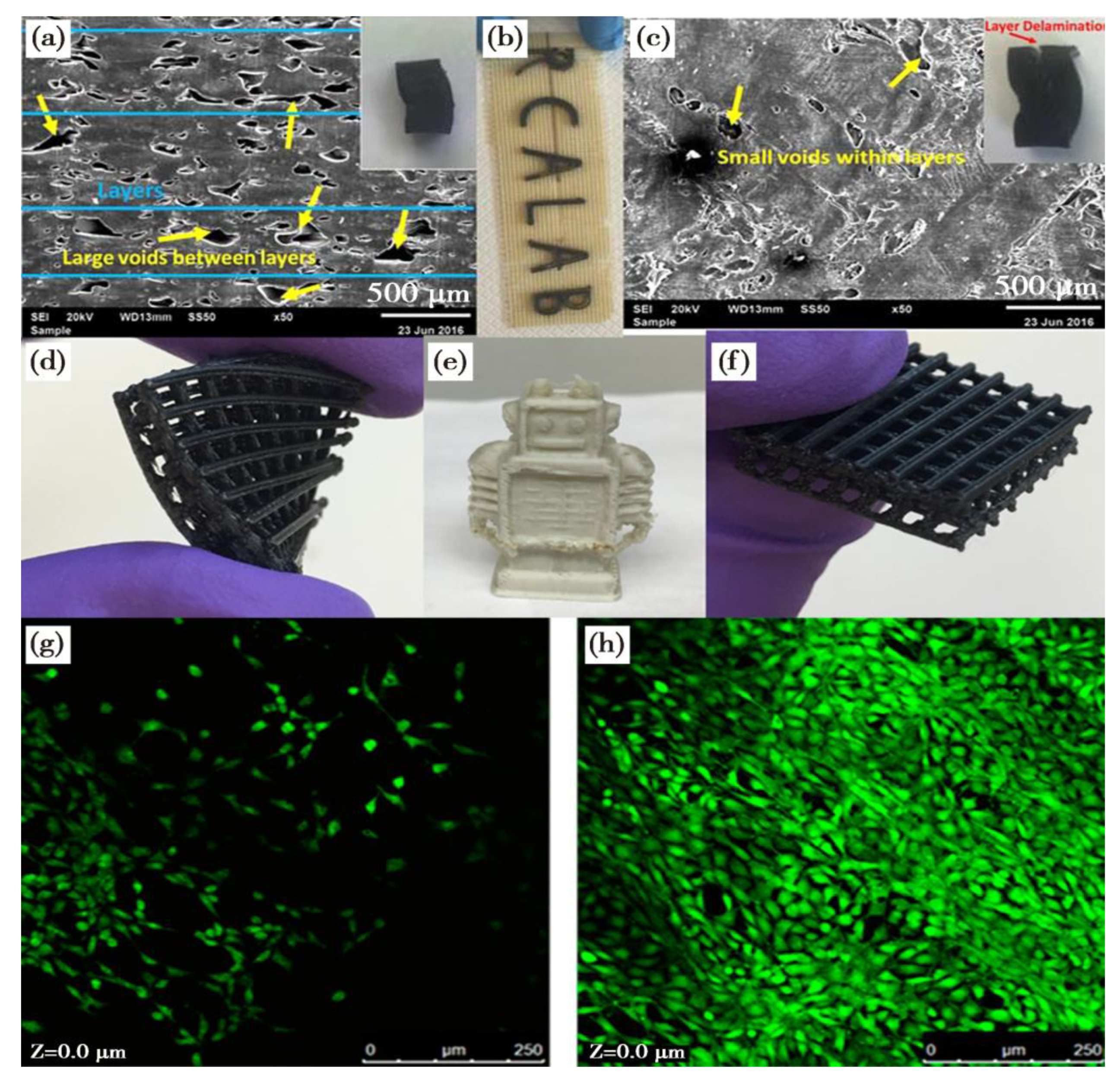
- Improve the FDM printing processes. Print parameters such as nozzle temperature, bed temperature, print speed, print orientation, layer height, etc., all play an important role in the performance of FDM-printed products. Currently, one of the main obstacles to the expansion of the FDM process is the slow printing speed [142], and how to improve the heat transfer properties of the printed material is an important factor for improving the FDM printing rate [143]. In addition, FDM is still not an alternative to traditional techniques (e.g., injection moulding) in terms of large-scale applications. The main issues including porosity, gaps between layers and the grating generated during the FDM process still widely exist.
- Reduce the printing costs. For the manufacturing of small quantities of parts, FDM is often less costly than traditional manufacturing methods as it does not require the tooling process. However, the raw material for FDM printing is usually expensive. In addition, the printing filaments used for FDM require high dimensional accuracy to maintain good print quality. Due to the limited print resolution, post-processing is usually required for the final products. Compared to processes such as injection moulding, FDM generally consumes more energy and time.
- Improve the recyclability of FDM printing materials. As more and more low-cost FDM devices enter the market, excessive waste of materials to produce low-value parts should be considered. From the perspective of materials development, reduced waste can be achieved by reducing support materials. Furthermore, one of the advantages of many thermoplastics is the recyclability. As FDM-manufactured parts are increasingly needed, their recyclability must be further explored to reduce the environmental burden of plastic pollution.
Author Contributions
Funding
Data Availability Statement
Acknowledgments
Conflicts of Interest
References
- Daminabo, S.C.; Goel, S.; Grammatikos, S.A.; Nezhad, H.Y.; Thakur, V.K. Fused deposition modeling-based additive manufacturing (3D printing): Techniques for polymer material systems. Mater. Today Chem. 2020, 16, 100248. [Google Scholar] [CrossRef]
- Wu, H.; Fahy, W.; Kim, S.; Kim, H.; Zhao, N.; Pilato, L.; Kafi, A.; Bateman, S.; Koo, J. Recent developments in polymers/polymer nanocomposites for additive manufacturing. Prog. Mater. Sci. 2020, 111, 100638. [Google Scholar] [CrossRef]
- Crump, S.S. Apparatus and Method for Creating. Three-Dimensional Objects. U.S. Patent 5121329A, 30 October 1989. [Google Scholar]
- Wu, X.; Mu, F.; Lin, Z. Three-dimensional printing of graphene-based materials and the application in energy storage. Mater. Today Adv. 2021, 11, 100157. [Google Scholar] [CrossRef]
- Garzon-Hernandez, S.; Arias, A.; Garcia-Gonzalez, D. A continuum constitutive model for FDM 3D printed thermoplastics. Compos. Part B Eng. 2020, 201, 108373. [Google Scholar] [CrossRef]
- Fico, D.; Rizzo, D.; Casciaro, R.; Corcione, C.E. A Review of Polymer-Based Materials for Fused Filament Fabrication (FFF): Focus on Sustainability and Recycled Materials. Polymers 2022, 14, 465. [Google Scholar] [CrossRef]
- Kumar, L.J.; Nair, C.G.K. Current trends of additive manufacturing in the aerospace industry. In Advances in 3D Printing & Additive Manufacturing Technologies; Springer: Berlin/Heidelberg, Germany, 2017; pp. 39–54. [Google Scholar]
- Gao, X.; Yu, N.; Li, J. Influence of Printing Parameters and Filament Quality on Structure and Properties of Polymer Composite Components Used in the Fields of Automotive. Struct. Prop. Addit. Manuf. Polym. Compon. 2020, 2, 301–330. [Google Scholar]
- Vanaei, S.; Parizi, M.S.; Vanaei, S.; Salemizadehparizi, F.; Vanaei, H.R. An Overview on Materials and Techniques in 3D Bioprinting Toward Biomedical Application. Eng. Regen. 2021, 2, 022001. [Google Scholar] [CrossRef]
- Haryńska, A.; Kucinska-Lipka, J.; Sulowska, A.; Gubanska, I.; Kostrzewa, M.; Janik, H. Medical-grade PCL based polyurethane system for FDM 3D printing-characterization and fabrication. Materials 2019, 12, 887. [Google Scholar] [CrossRef] [PubMed]
- Chen, X.; Yang, R.; Wu, X. Printing of MXene-based materials and the applications: A state-of-the-art review. 2D Mater. 2022, 9, 042002. [Google Scholar] [CrossRef]
- Yang, R.; Chen, X.; Zheng, Y.; Chen, K.; Zeng, W.; Wu, X. Recent advances in the 3D printing of electrically conductive hydrogels for flexible electronics. J. Mater. Chem. C 2022, 10, 5380–5399. [Google Scholar] [CrossRef]
- Haleem, A.; Javaid, M. 3D printed medical parts with different materials using additive manufacturing. Clin. Epidemiol. Glob. Health 2020, 8, 215–223. [Google Scholar]
- ASTM ISO/ASTM52900-15; Standard Terminology for Additive Manufacturing—General Principles—Terminology. ASTM International: West Conshohocken, PA, USA, 2015.
- Quinlan, H.E.; Hasan, T.; Jaddou, J.; Hart, A.J. Industrial and Consumer Uses of Additive Manufacturing: A Discussion of Capabilities, Trajectories, and Challenges. J. Ind. Ecol. 2017, 21, S15–S20. [Google Scholar] [CrossRef]
- Wu, X.; Su, Y.; Shi, J. Perspective of additive manufacturing for metamaterials development. Smart Mater. Struct. 2019, 28, 093001. [Google Scholar] [CrossRef]
- Shanmugam, V.; Das, O.; Babu, K.; Marimuthu, U.; Veerasimman, A.; Johnson, D.J.; Neisiany, R.E.; Hedenqvist, M.S.; Ramakrishna, S.; Berto, F. Fatigue behaviour of FDM-3D printed polymers, polymeric composites and architected cellular materials. Int. J. Fatigue 2021, 143, 106007. [Google Scholar] [CrossRef]
- Rajan, K.; Samykano, M.; Kadirgama, K.; Harun, W.S.W. Fused deposition modeling: Process, materials, parameters, properties, and applications. Int. J. Adv. Manuf. Technol. 2022, 120, 1531–1570. [Google Scholar] [CrossRef]
- Mishra, V.; Negi, S.; Kar, S.; Sharma, A.K.; Rajbahadur, Y.N.K.; Kumar, A. Recent advances in fused deposition modeling based additive manufacturing of thermoplastic composite structures: A review. J. Thermoplast. Compos. Mater. 2022, 36, 7. [Google Scholar] [CrossRef]
- Mogan, J.; Harun, W.S.W.; Kadirgama, K.; Ramasamy, D.; Foudzi, F.M.; Sulong, A.B.; Tarlochan, F.; Ahmad, F. Fused Deposition Modelling of Polymer Composite: A Progress. Polymers 2023, 15, 28. [Google Scholar] [CrossRef]
- Tofail, S.A.M.; Koumoulos, E.P.; Bandyopadhyay, A.; Bose, S.; O’Donoghue, L.; Charitidis, C. Additive manufacturing: Scientific and technological challenges, market uptake and opportunities. Mater. Today 2018, 21, 22–37. [Google Scholar] [CrossRef]
- Karaman, E.; Colak, O. The effects of process parameters on mechanical properties and microstructures of parts in fused deposition modeling. Duzce Univ. J. Sci. Technol. 2020, 8, 617–630. [Google Scholar]
- Kam, M.; Ipekci, A.; Sengul, O. Effect of FDM process parameters on the mechanical properties and production costs of 3D printed Powder ABS samples. Int. J. Anal. Exp. Finite Elem. Anal. 2020, 7, 77–90. [Google Scholar]
- Wu, X.; Mu, F.; Zhao, H. Synthesis and potential applications of nanoporous graphene: A review. Proc. Nat. Res. Soc 2018, 2, 02003. [Google Scholar] [CrossRef]
- Culmone, C.; Smit, G.; Breedveld, P. Additive manufacturing of medical instruments: A state-of-the-art review. Addit. Manuf. 2019, 27, 461–473. [Google Scholar] [CrossRef]
- Wang, X.; Jiang, M.; Zhou, Z.; Gou, J.; Hui, D. 3D printing of polymer matrix composites: A review and prospective. Compos. Part B Eng. 2017, 110, 442–458. [Google Scholar] [CrossRef]
- Ivanova, O.; Williams, C.; Campbell, T. Additive manufacturing (AM) and nanotechnology: Promises and challenges. Compos. Part B Eng. 2013, 19, 353–364. [Google Scholar] [CrossRef]
- Sanatgar, R.H.; Campagne, C.; Nierstrasz, V. Investigation of the adhesion properties of direct 3D printing of polymers and nanocomposites on textiles: Effect of FDM printing process parameters. Appl. Surf. Sci. 2017, 403, 551–563. [Google Scholar] [CrossRef]
- Wu, X. Influence of Particle Beam Irradiation on the Structure and Properties of Graphene; Springer: Berlin/Heidelberg, Germany, 2017. [Google Scholar]
- Tymrak, B.M.; Kreiger, M.; Pearce, J.M. Mechanical properties of components fabricated with open-source 3-D printers under realistic environmental conditions. Mater. Des. 2014, 58, 242–246. [Google Scholar] [CrossRef]
- Mohamed, O.A.; Masood, S.H.; Bhowmik, J.L. Optimization of fused deposition modeling process parameters: A review of current research and future prospects. Adv. Manuf. 2015, 3, 42–53. [Google Scholar] [CrossRef]
- Crump, S.S. Apparatus and Method for Creating Three-Dimensional Objects. U.S. Patent 5, 9 June 1992. [Google Scholar]
- Crump, S.S.; Comb, J.W.; Priedeman, W.R., Jr.; Zinniel, R.L. Process of Support Removal for Fused Deposition Modeling. U.S. Patent 5, 2 April 1996. [Google Scholar]
- Goh, G.D.; Yap, Y.L.; Tan, H.K.J.; Sing, S.L.; Goh, G.L.; Yeong, W.Y. Process- structure-properties in polymer additive manufacturing via material extrusion: A review. Crit. Rev. Solid State Mater. Sci. 2020, 45, 113–133. [Google Scholar] [CrossRef]
- Sohrabian, M.; Vaseghi, M.; Khaleghi, H.; Dehrooyeh, S.; Kohan, M.S.A. Structural investigation of delicate-geometry fused deposition modeling additive manufacturing scaffolds: Experiment and analytics. J. Mater. Eng. Perform. 2021, 30, 6529–6541. [Google Scholar] [CrossRef]
- Vyavahare, S.; Teraiya, S.; Panghal, D.; Kumar, S. Fused deposition modeling: A review. Rapid Prototyp. J. 2020, 26, 176–201. [Google Scholar] [CrossRef]
- Delic, M.; Eyers, D.R. The effect of additive manufacturing adoption on supply chain flexibility and performance: An empirical analysis from the automotive industry. Int. J. Prod. Econ. 2020, 228, 107689. [Google Scholar] [CrossRef]
- Penumakala, P.K.; Santo, J.; Thomas, A. A critical review on the fused deposition modeling of thermoplastic polymer composites. Compos. Part B Eng. 2020, 201, 108336. [Google Scholar] [CrossRef]
- Zhang, P.; Wang, Z.; Li, J.; Li, X.; Cheng, L. From materials to devices using fused deposition modeling: A state-of-art review. Nanotechnol. Rev. 2020, 9, 1594–1609. [Google Scholar] [CrossRef]
- Gao, X.; Qi, S.; Kuang, X.; Su, Y.; Li, J.; Wang, D. Fused filament fabrication of polymer materials: A review of interlayer bond. Addit. Manuf. 2021, 37, 101658. [Google Scholar] [CrossRef]
- Romanov, V.; Samuel, R.; Chaharlang, M.; Jafek, A.R.; Frost, A.; Gale, B.K. FDM 3D Printing of High-Pressure, Heat-Resistant, Transparent Microfluidic Devices. Anal. Chem. 2018, 90, 10450–10456. [Google Scholar] [CrossRef]
- Turner, N.; Strong, R.; Gold, A.S. A review of melt extrusion additive manufacturing processes: I. Process design and modeling. Rapid Prototyp. J. 2014, 20, 192–204. [Google Scholar] [CrossRef]
- Turner, B.N.; Strong, R. A review of melt extrusion additive manufacturing processes: II. Materials, dimensional accuracy, and surface roughness. Rapid Prototyp. J. 2015, 21, 250–261. [Google Scholar] [CrossRef]
- Singh, R.; Singh, S.; Singh, I.P.; Fabbrocino, F.; Fraternali, F. Investigation for surface finish improvement of FDM parts by vapor smoothing process. Rapid Prototyp. J. 2017, 111, 228–234. [Google Scholar] [CrossRef]
- Mahfuz, H.; Khan, M.R.; Leventouri, T.; Liarokapis, E. Investigation of MWCNT reinforcement on the strain hardening behavior of ultrahigh molecular weight polyethylene. J. Nanotechnol. 2011, 2011, 637395. [Google Scholar] [CrossRef]
- Mohan, N.; Senthil, P.; Vinodh, S.; Jayanth, N. A review on composite materials and process parameters optimisation for the fused deposition modelling process. Virtual Phys. Prototyp. 2017, 12, 47–59. [Google Scholar] [CrossRef]
- Medellin-Castillo, H.I.; Zaragoza-Siqueiros, J. Design and manufacturing strategies for fused deposition modelling in additive manufacturing: A review. Chin. J. Mech. Eng. 2019, 32, 53. [Google Scholar] [CrossRef]
- Algarni, M.; Ghazali, S. Comparative study of the sensitivity of PLA, ABS, PEEK, and PETG’s mechanical properties to FDM printing process parameters. Crystals 2021, 11, 995. [Google Scholar] [CrossRef]
- Pervaiz, S.; Qureshi, T.A.; Kashwani, G.; Kannan, S. 3D printing of fiber- reinforced plastic composites using fused deposition modeling: A status review. Materials 2021, 14, 4520. [Google Scholar] [CrossRef] [PubMed]
- Rett, J.P.; Traore, Y.L.; Ho, E.A. Sustainable materials for fused deposition modeling 3D printing applications. Adv. Eng. Mater. 2021, 23, 2001472. [Google Scholar] [CrossRef]
- Vidakis, N.; Petousis, M.; Korlos, A.; Velidakis, E.; Mountakis, N.; Charou, C.; Myftari, A. Strain rate sensitivity of polycarbonate and thermoplastic polyurethane for various 3d printing temperatures and layer heights. Polymers 2021, 13, 2752. [Google Scholar] [CrossRef]
- Vidakis, N.; Petousis, M.; Velidakis, E.; Liebscher, M.; Mechtcherine, V.; Tzounis, L. On the strain rate sensitivity of fused filament fabrication (Fff) processed pla, abs, petg, pa6, and pp thermoplastic polymers. Polymers 2020, 12, 2924. [Google Scholar] [CrossRef]
- Nabavi-Kivi, A.; Ayatollahi, M.R.; Razavi, S.M.J. Investigating the effect of raster orientation on fracture behavior of 3D-printed ABS specimens under tension-tear loading. Eur. J. Mech. A/Solids 2023, 99, 104944. [Google Scholar] [CrossRef]
- Dul, S.; Gutierrez, B.J.A.; Pegoretti, A.; Alvarez-Quintana, J.; Fambri, L. 3D printing of ABS Nanocomposites. Comparison of processing and effects of multi-wall and single-wall carbon nanotubes on thermal, mechanical and electrical properties. J. Mater. Sci. Technol. 2022, 121, 52–66. [Google Scholar] [CrossRef]
- Alhallak, L.M.; Tirkes, S.; Tayfun, U. Mechanical, thermal, melt-flow and morphological characterizations of bentonite-filled ABS copolymer. Rapid Prototyp. J. 2020, 26, 1305–1312. [Google Scholar] [CrossRef]
- Cress, A.K.; Huynh, J.; Anderson, E.H.; O’neill, R.; Schneider, Y. Effect of recycling on the mechanical behavior and structure of additively manufactured acrylonitrile butadiene styrene (ABS). J. Clean. Prod. 2021, 279, 123689. [Google Scholar] [CrossRef]
- Fornells, E.; Murray, E.; Waheed, S.; Morrin, A.; Diamond, D.; Paull, B.; Breadmore, M. Integrated 3D printed heaters for microfluidic applications: Ammonium analysis within environmental water. Anal. Chim. Acta 2020, 1098, 94–101. [Google Scholar] [CrossRef]
- Yang, Z.; He, F.; Khan, M. An Empirical Torsional Spring Model for the Inclined Crack in a 3D-Printed Acrylonitrile Butadiene Styrene (ABS) Cantilever Beam. Polymers 2023, 15, 496. [Google Scholar] [CrossRef]
- Farsi, M.; Asefnejad, A.; Baharifar, H. A hyaluronic acid/PVA electrospun coating on 3D printed PLA scaffold for orthopedic application. Prog. Biomater. 2022, 11, 67–77. [Google Scholar] [CrossRef] [PubMed]
- Marșavina, L.; Vălean, C.; Mărghitaș, M.; Linul, E.; Razavi, N.; Berto, F.; Brighenti, R. Effect of the manufacturing parameters on the tensile and fracture properties of FDM 3D-printed PLA specimens. Eng. Fract. Mech. 2022, 274, 108766. [Google Scholar] [CrossRef]
- Arrigo, R.; Frache, A. FDM Printability of PLA Based-Materials: The Key Role of the Rheological Behavior. Polymers 2022, 14, 1754. [Google Scholar] [CrossRef]
- Song, Y.; Li, Y.; Song, W.; Yee, K.; Lee, K.Y.; Tagarielli, V.L. Measurements of the mechanical response of unidirectional 3D-printed PLA. Mater. Des. 2017, 123, 154–164. [Google Scholar] [CrossRef]
- Yao, T.; Ye, J.; Deng, Z.; Zhang, K.; Ma, Y.; Ouyang, H. Tensile failure strength and separation angle of FDM 3D printing PLA material: Experimental and theoretical analyses. Compos. Part B Eng. 2020, 188, 107894. [Google Scholar] [CrossRef]
- Huang, J.; Koutsos, V.; Radacsi, N. Low-cost FDM 3D-printed modular electrospray/electrospinning setup for biomedical applications. 3D Print. Med. 2020, 6, 8. [Google Scholar] [CrossRef] [PubMed]
- Sanatgar, R.H.; Cayla, A.; Guan, J.; Chen, G.; Nierstrasz, V.; Campagne, C. Piezoresistive Properties of 3D-Printed Polylactic Acid (PLA) Nanocomposites. Polymers 2022, 14, 2981. [Google Scholar] [CrossRef] [PubMed]
- Amza, C.G.; Zapciu, A.; Baciu, F.; Radu, C. Effect of UV-C Radiation on 3D Printed ABS-PC Polymers. Polymers 2023, 15, 1966. [Google Scholar] [CrossRef]
- Tambrallimath, V.; Keshavamurthy, R.; Bavan, S.D.; Patil, A.Y.; Khan, T.M.Y.; Badruddin, I.A.; Kamangar, S. Mechanical Properties of PC-ABS-Based Graphene-Reinforced Polymer Nanocomposites Fabricated by FDM Process. Polymers 2021, 13, 2951. [Google Scholar] [CrossRef]
- Andrzejewski, J.; Mohanty, A.K.; Misra, M. Development of hybrid composites reinforced with biocarbon/carbon fiber system. The comparative study for PC, ABS and PC/ABS based materials. Compos. Part B Eng. 2020, 200, 108319. [Google Scholar] [CrossRef]
- Huang, M.Z.; Nomai, J.; Schlarb, A.K. The effect of different processing, injection molding (IM) and fused deposition modeling (FDM), on the environmental stress cracking (ESC) behavior of filled and unfilled polycarbonate (PC). Express Polym. Lett. 2021, 15, 3. [Google Scholar] [CrossRef]
- Dua, R.; Rashad, Z.; Spears, J.; Dunn, G.; Maxwell, M. Applications of 3D-Printed PEEK via Fused Filament Fabrication: A Systematic Review. Polymers 2021, 13, 4046. [Google Scholar] [CrossRef] [PubMed]
- Han, X.; Yang, D.; Yang, C.; Spintzyk, S.; Scheideler, L.; Li, P.; Li, D.; Geis-Gerstorfer, J.; Rupp, F. Carbon Fiber Reinforced PEEK Composites Based on 3D-Printing Technology for Orthopedic and Dental Applications. J. Clin. Med. 2019, 8, 240. [Google Scholar] [CrossRef]
- Wang, P.; Zou, B.; Ding, S.; Huang, C.; Shi, Z.; Ma, Y.; Yao, P. Preparation of short CF/GF reinforced PEEK composite filaments and their comprehensive properties evaluation for FDM-3D printing. Compos. Part B Eng. 2020, 198, 108175. [Google Scholar] [CrossRef]
- Rinaldi, M.; Cecchini, F.; Pigliaru, L.; Ghidini, T.; Lumaca, F.; Nanni, F. Additive manufacturing of polyether ether ketone (PEEK) for space applications: A nanosat polymeric structure. Polymers 2021, 13, 11. [Google Scholar] [CrossRef] [PubMed]
- Valvez, S.; Silva, A.P.; Reis, P.N.B. Optimization of Printing Parameters to Maximize the Mechanical Properties of 3D-Printed PETG-Based Parts. Polymers 2022, 14, 2564. [Google Scholar] [CrossRef] [PubMed]
- Valvez, S.; Reis, P.N.G.; Ferreira, J.A.M. Effect of annealing treatment on mechanical properties of 3D-Printed composites. J. Mater. Res. Technol. 2023, 23, 2101–2115. [Google Scholar] [CrossRef]
- Hsueh, M.H.; Lai, C.J.; Wang, S.H.; Zeng, Y.S.; Hsieh, C.H.; Pan, C.Y.; Huang, W.C. Effect of Printing Parameters on the Thermal and Mechanical Properties of 3D-Printed PLA and PETG, Using Fused Deposition Modeling. Polymers 2021, 13, 1758. [Google Scholar] [CrossRef]
- Guessasma, S.; Belhabib, S.; Nouri, H. Printability and Tensile Performance of 3D Printed Polyethylene Terephthalate Glycol Using Fused Deposition Modelling. Polymers 2019, 11, 1220. [Google Scholar] [CrossRef]
- Fu, X.; Zhang, X.; Huang, Z. Axial crushing of Nylon and Al/Nylon hybrid tubes by FDM 3D printing. Compos. Struct. 2021, 256, 113055. [Google Scholar] [CrossRef]
- Lay, M.; Thajudin, N.L.N.; Hamid, Z.A.A.; Rusli, A.; Abdullah, M.K.; Shuib, R.K. Comparison of physical and mechanical properties of PLA, ABS and nylon 6 fabricated using fused deposition modeling and injection molding. Compos. Part B Eng. 2019, 176, 107341. [Google Scholar] [CrossRef]
- Farina, I.; Singh, N.; Colangelo, F.; Luciano, R.; Bonazzi, G.; Fraternali, F. High- performance nylon-6 sustainable filaments for additive manufacturing. Materials 2019, 12, 3955. [Google Scholar] [CrossRef] [PubMed]
- Li, B.; Zhang, S.; Gao, Y.; Xuan, F. Strain sensing behavior of FDM 3D printed carbon black filled TPU with periodic configurations and flexible substrates. J. Manuf. Process. 2022, 74, 283–295. [Google Scholar] [CrossRef]
- Wang, Y.; Zhang, J.; Li, M.; Lei, M.; Wang, Y.; Wei, Q. 3D printing thermo-responsive shape memory polymer composite based on PCL/TPU blends. J. Polym. Res. 2022, 29, 243. [Google Scholar] [CrossRef]
- Ding, S.; Zou, B.; Wang, P.; Ding, H. Effects of nozzle temperature and building orientation on mechanical properties and microstructure of PEEK and PEI printed by 3D-FDM. Polym. Test. 2019, 78, 105948. [Google Scholar] [CrossRef]
- Vakharia, V.S.; Leonard, H.; Singh, M.; Halbig, M.C. Multi-Material Additive Manufacturing of High Temperature Polyetherimide (PEI)-Based Polymer Systems for Lightweight Aerospace Applications. Polymers 2023, 15, 561. [Google Scholar] [CrossRef]
- McCoul, D.; Nie, W.; Kim, P.; Kengla, C.; Clouse, C.; Atala, A. Thermoplastic polycaprolactone elastomer for a 3D-printed pericardial scaffold in the treatment of dilated cardiomyopathy. Bioprinting 2022, 28, e00252. [Google Scholar] [CrossRef]
- Sodeifian, G.; Ghaseminejad, S.; Yousefi, A.A. Preparation of polypropylene/short glass fiber composite as Fused Deposition Modeling (FDM) filament. Results Phys. 2019, 12, 205–222. [Google Scholar] [CrossRef]
- Carneiro, O.S.; Silva, A.F.; Gomes, R. Fused deposition modeling with polypropylene. Mater. Des. 2015, 83, 768–776. [Google Scholar] [CrossRef]
- Cano-Vicent, A.; Tambuwala, M.M.; Hassan, S.S.; Barh, D.; Aljabali, A.A.; Birkett, M.; Arjunan, A.; Serrano-Aroca, Á. Fused deposition modelling: Current status, methodology, applications and future prospects. Addit. Manuf. 2021, 47, 102378. [Google Scholar] [CrossRef]
- Wickramasinghe, S.; Do, T.; Tran, P. FDM-Based 3D Printing of Polymer and Associated Composite: A Review on Mechanical Properties, Defects and Treatments. Polymers 2020, 12, 1529. [Google Scholar] [CrossRef]
- Leigh, S.J.; Bradley, R.J.; Purssell, C.P.; Billson, D.R.; Hutchins, D.A. A Simple, Low-Cost Conductive Composite Material for 3D Printing of Electronic Sensors. PLoS ONE 2012, 7, e49365. [Google Scholar] [CrossRef]
- Kwok, S.W.; Goh, K.H.H.; Tan, Z.D.; Tan, S.T.M.; Tjiu, W.W.; Soh, J.Y.; Ng, Z.J.G.; Chan, Y.Z.; Hui, H.K.; Goh, K.E.J. Electrically conductive filament for 3D-printed circuits and sensors. Appl. Mater. Today 2017, 9, 167–175. [Google Scholar] [CrossRef]
- Gnanasekaran, K.; Heijmans, T.; Bennekom, S.V.; Woldhuis, H.; Wijnia, S.; de With, G.; Friedrich, H. 3D printing of CNT- and graphene-based conductive polymer nan-ocomposites by fused deposition modeling. Appl. Mater. Today 2017, 9, 21–28. [Google Scholar] [CrossRef]
- Dul, S.; Fambri, L.; Pegoretti, A. Filaments production and fused deposition modelling of ABS/carbon nanotubes composites. Nanomaterials 2018, 8, 49. [Google Scholar] [CrossRef]
- Dorigato, A.; Moretti, V.; Dul, S.; Unterberger, S.H.; Pegoretti, A. Electrically cond-uctive nanocomposites for fused deposition modelling. Synth. Met. 2017, 226, 7–14. [Google Scholar] [CrossRef]
- Tsiakatouras, G.; Tsellou, E.; Stergiou, C. Compara-tive study on nanotubes reinforced with carbon filaments for the 3D printing of mechanical parts. World Trans. Eng. Technol. Educ. 2014, 12, 392–396. [Google Scholar]
- Thomas, D.J. Developing nanocomposite 3D printing filaments for enhanced integrated device fabrication. Int. J. Adv. Manuf. Technol. 2018, 95, 4191–4198. [Google Scholar] [CrossRef]
- Schmitz, D.P.; Ecco, L.G.; Dul, S.; Pereira, E.C.L.; Soares, B.G.; Barra, G.M.O.; Pegoretti, A. Electromagnetic interf-erence shielding effectiveness of ABS carbon-based composites manufactured via fused deposition modelling. Mater. Today Commun. 2018, 15, 70–80. [Google Scholar] [CrossRef]
- Yu, W.W.; Zhang, J.; Wu, J.R.; Wang, X.Z.; Deng, Y.H. Incorporation of graphitic nano-filler and poly (lactic acid) in fused deposition modeling. J. Appl. Polym. Sci. 2017, 134, 15. [Google Scholar] [CrossRef]
- Spinelli, G.; Kotsilkova, R.; Ivanov, E.; Georgiev, V.; Ivanova, R.; Naddeo, C.; Romano, V. Dielectric Spectroscopy and Thermal Properties of Poly(lactic) Acid Reinforced with Carbon-Based Particles: Experimental Study and Design Theory. Polymers 2020, 12, 2414. [Google Scholar] [CrossRef] [PubMed]
- Wang, P.; Song, T.; Abo-Dief, H.M.; Song, J.; Alanazi, A.K.; Fan, B.; Huang, M.; Lin, Z.; Altalhi, A.A.; Gao, S.; et al. Effect of carbon nanotubes on the interface evolution and dielectric properties of polylactic acid/ethylene-vinyl acetate copolymer nanocomposites. Adv. Compos. Hybrid Mater. 2022, 5, 1100–1110. [Google Scholar] [CrossRef]
- DAS Ramôa, S.; Barra, G.M.; Oliveira, R.V.; de Oliveira, M.G.; Cossa, M.; Soares, B.G. Electrical, rheological and electromagnetic interference shielding properties of thermoplastic polyurethane/carbon nanotube composites. Polym. Int. 2013, 62, 1477–1484. [Google Scholar] [CrossRef]
- Kim, K.; Park, J.; Suh; Kim, M.; Jeong, Y.; Park, I. 3D printing of multiaxial force sensors using carbon nanotube (CNT)/thermoplastic polyurethane (TPU) filaments. Sens. Actuators A Phys. 2017, 263, 493–500. [Google Scholar] [CrossRef]
- Gonçalves, J.; Lima, P.; Krause, B.; Pötschke, P.; Lafont, U.; Gomes, J.R.; Abreu, C.S.; Paiva, M.C.; Covas, J.A. Electrically Conductive Polyetheretherketone Nanocomposite Filaments: From Production to Fused Deposition Modeling. Polymers 2018, 10, 925. [Google Scholar] [CrossRef] [PubMed]
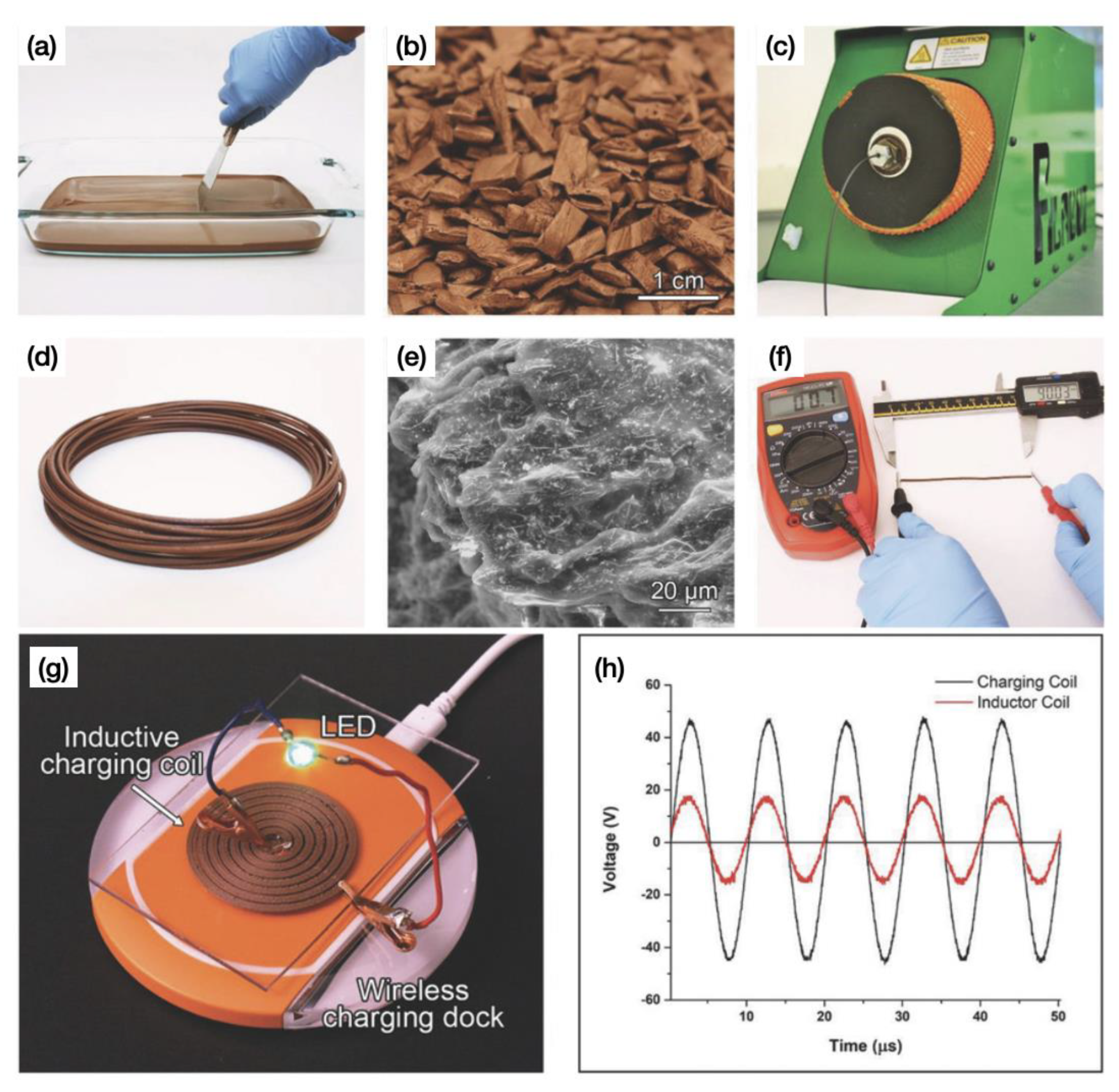
- Le Guen, M.-J.; Hill, S.; Smith, D.; Theobald, B.; Gaugler, E.; Barakat, A.; Mayer-Laigle, C. Influence of rice husk and wood biomass properties on the manufacture of filaments for fused deposition modeling. Front. Chem. 2019, 7, 735. [Google Scholar] [CrossRef]
- Coppola, B.; Cappetti, N.; Maio, L.D.; Scarfato, P. 3D printing of PLA/clay nanocomposites: Influence of printing temperature on printed samples properties. Materials 2018, 11, 1947. [Google Scholar] [CrossRef]
- Weng, Z.; Wang, J.; Senthil, T.; Wu, L. Mechanical and thermal properties of ABS/montmorillonite nanocomposites for fused deposition modeling 3D printing. Mater. Des. 2016, 102, 276–283. [Google Scholar] [CrossRef]
- Meng, S.; He, H.; Jia, Y.; Yu, P.; Huang, B.; Chen, J. Effect of nanoparticles on the mechanical properties of acrylonitrile–butadiene–styrene specimens fabricated by fused deposition modeling. J. Appl. Polym. Sci. 2017, 134, 7. [Google Scholar] [CrossRef]
- Gao, J.; Hao, M.; Wang, Y.; Kong, X.; Yang, B.; Wang, R. 3D printing boron nitride nanosheets filled thermoplastic polyurethane composites with enhanced mechanical and thermal conductive properties. Addit. Manuf. 2022, 56, 102897. [Google Scholar]
- Akhoundi, B.; Behravesh, A.H.; Saed, A.B. An innovative design approach in three-dimensional printing of continuous fiber-reinforced thermoplastic composites via fused deposition modeling process: In-melt simultaneous impregnation. Proc. Inst. Mech. Eng. Part B J. Eng. Manuf. 2020, 234, 243–259. [Google Scholar] [CrossRef]
- Wang, F.; Zhang, Z.; Ning, F.; Wang, G.; Dong, C. A mechanistic model for tensile property of continuous carbon fiber reinforced plastic composites built by fused filament fabrication. Addit. Manuf. 2020, 32, 101102. [Google Scholar] [CrossRef]
- Somireddy, M.; Singh, C.V.; Czekanski, A. Mechanical behavior of 3D printed composite parts with short carbon fiber reinforcements. Eng. Fail. Anal. 2020, 107, 104232. [Google Scholar] [CrossRef]
- Brenken, B.; Barocio, E.; Favaloro, A.; Kunc, V.; Pipes, R.B. Fused filament fabrication of fiber-reinforced polymers: A review. Addit. Manuf. 2018, 21, 1–16. [Google Scholar] [CrossRef]
- Shofner, M.L.; Lozano, K.; Rodríguez-Macías, F.J.; Barrera, E.V. Nanofiber-reinforced polymers prepared by fused deposition modeling. J. Appl. Polym. Sci. 2003, 89, 3081–3090. [Google Scholar] [CrossRef]
- Tekinalp, H.L.; Kunc, V.; Velez-Garcia, G.M.; Duty, C.E.; Love, L.J.; Naskar, A.K.; Blue, C.A.; Ozcan, S. Highly oriented carbon fiber-polymer composites via additive manufacturing. Compos. Sci. Technol. 2014, 105, 144–150. [Google Scholar] [CrossRef]
- Li, Q.; Zhao, W.; Li, Y.; Yang, W.; Wang, G. Flexural properties and fracture behavior of CF/PEEK in orthogonal building orientation by FDM: Microstructure and mechanism. Polymers 2019, 11, 656. [Google Scholar] [CrossRef]
- Spoerk, M.; Savandaiah, C.; Arbeiter, F.; Traxler, G.; Cardon, L.; Holzer, C.; Sapkota, J. Anisotropic properties of oriented short carbon fibre filled polypropylene parts fabricated by extrusion-based additive manufacturing. Compos. Part A Appl. Sci. Manuf. 2018, 113, 95–104. [Google Scholar] [CrossRef]
- Magri, A.E.; Vanaei, S.; Shirinbayan, M.; Vaudreuil, S.; Tcharkhtchi, A. An investigation to study the effect of process parameters on the strength and fatigue behavior of 3d-printed pla-graphene. Polymers 2021, 13, 3218. [Google Scholar] [CrossRef]
- Zhang, X.J.; Xiao, J.H.; Kim, J.K.; Cao, L. A Comparative Analysis of Chemical, Plasma and In Situ Modification of Graphene Nanoplateletes for Improved Performance of Fused Filament Fabricated Thermoplastic Polyurethane Composites Parts. Polymers 2022, 14, 5182. [Google Scholar] [CrossRef] [PubMed]
- Dul, S.; Fambri, L.; Pegoretti, A. Fused deposition modelling with ABS- graphene nanocomposites. Compos. Part A Appl. Sci. Manuf. 2016, 85, 181–191. [Google Scholar] [CrossRef]
- Rostom, S.; Dadmun, M.D. Improving heat transfer in fused deposition modeling with graphene enhances inter filament bonding. Polym. Chem. 2019, 10, 5967–5978. [Google Scholar] [CrossRef]
- Prashantha, K.; Roger, F. Multifunctional properties of 3D printed poly(lactic acid)/graphene nanocomposites by fused deposition modeling. J. Macromol. Sci. Part A 2017, 54, 24–29. [Google Scholar] [CrossRef]
- Yang, L.; Chen, Y.; Wang, M.; Shi, S.; Jing, J. Fused Deposition Modeling 3D Printing of Novel Poly (vinyl alcohol)/Graphene Nanocomposite with Enhanced Mechanical and Electromagnetic Interference Shielding Properties. Ind. Eng. Chem. Res. 2020, 59, 8066–8077. [Google Scholar] [CrossRef]
- Zhu, D.; Ren, Y.; Liao, G.; Jiang, S.; Liu, F.; Guo, J.; Xu, G. Thermal and mechanical properties of polyamide 12/graphene nanoplatelets nanocomposites and parts fabricated by fused deposition modeling. J. Appl. Polym. Sci. 2017, 134, 45332. [Google Scholar] [CrossRef]
- Jing, J.; Xiong, Y.; Shi, S.; Pei, H.; Chen, Y.; Lambin, P. Facile fabrication of lightweight porous FDM-Printed polyethylene/graphene nanocomposites with enhanced interfacial strength for electromagnetic interference shielding. Compos. Sci. Technol. 2021, 207, 108732. [Google Scholar] [CrossRef]
- Abdullah, T.; Qurban, R.O.; Bolarinwa, S.O.; Mirza, A.A.; Pasovic, M.; Memic, A. 3D Printing of Metal/Metal Oxide Incorporated Thermoplastic Nanocomposites With Antimicrobial Properties. Front. Bioeng. Biotechnol. 2020, 8, 568186. [Google Scholar] [CrossRef]
- Nabipour, M.; Akhoundi, B.; Saed, A.B. Manufacturing of polymer/metal composites by fused deposition modeling process with polyethylene. J. Appl. Polym. Sci. 2020, 137, 48717. [Google Scholar] [CrossRef]
- Chen, L.; Zhang, X. Modification the surface quality and mechanical properties by laser polishing of Al/PLA part manufactured by fused deposition modeling. Appl. Surf. Sci. 2019, 492, 765–775. [Google Scholar] [CrossRef]
- Chen, L.; Zhang, X.; Wang, Y.; Osswald, T.A. Laser polishing of Cu/PLA composite parts fabricated by fused deposition modeling: Analysis of surface finish and mechanical properties. Polym. Compos. 2020, 41, 1356–1368. [Google Scholar] [CrossRef]
- Bayraktar, I.; Doganay, D.; Coskun, S.; Kaynak, C.; Akca, G.; Unalan, H.E. 3D printed antibacterial silver nanowire/polylactide nanocomposites. Compos. Part B Eng. 2019, 172, 671–678. [Google Scholar] [CrossRef]
- Podstawczyk, D. Preparation of antimicrobial 3D printing filament: In situ thermal formation of silver nanoparticles during the material extrusion. Polym. Compos. 2020, 41, 4692–4705. [Google Scholar] [CrossRef]
- Cruz, M.A.; Ye, S.; Kim, M.J.; Reyes, C.; Yang, F.; Flowers, P.F.; Wiley, B.J. Multigram synthesis of Cu-Ag Core-shell nanowires enables the production of a highly conductive polymer filament for 3D printing electronics. Part. Part. Syst. Charact. 2018, 35, 1700385. [Google Scholar] [CrossRef]
- Tan, J.C.; Low, H.Y. Embedded electrical tracks in 3D printed objects by fused filament fabrication of highly conductive composites. Addit. Manuf. 2018, 23, 294–302. [Google Scholar] [CrossRef]
- Wajahat, M.; Kim, J.H.; Ahn, J.; Lee, S.; Bae, J.; Pyo, J.; Seol, S.K. 3D printing of Fe3O4 functionalized graphene-polymer (FGP) composite microarchitectures. Carbon 2020, 167, 278–284. [Google Scholar] [CrossRef]
- Xiang, D.; Zhang, X.; Harkin-Jones, E.; Zhu, W.; Zhou, Z.; Shen, Y.; Li, Y.; Zhao, C.; Wang, P. Synergistic effects of hybrid conductive nanofillers on the performance of 3D printed highly elastic strain sensors. Compos. Part A Appl. Sci. Manuf. 2020, 129, 105730. [Google Scholar] [CrossRef]
- Wei, H.; Cauchy, X.; Navas, I.O.; Abderrafai, Y.; Chizari, K.; Sundararaj, U.; Liu, Y.; Leng, J.; Therriault, D. Direct 3D printing of hybrid nanofiber-based nanocomposites for highly conductive and shape memory applications. ACS Appl. Mater. Interfaces 2019, 11, 24523–24532. [Google Scholar] [CrossRef]
- Wei, X.; Li, D.; Jiang, W.; Gu, Z.; Wang, X.; Zhang, Z.; Sun, Z. 3D printable graphene composite. Sci. Rep. 2015, 5, 11181. [Google Scholar] [CrossRef]
- Yamamoto, B.E.; Trimble, A.Z.; Minei, B.; Nejhad, M.N.G. Development of multifunctional nanocomposites with 3-D printing additive manufacturing and low graphene loading. J. Thermoplast. Compos. Mater. 2019, 32, 383–408. [Google Scholar] [CrossRef]
- Chen, Q.; Mangadlao, J.D.; Wallat, J.; De Leon, A.; Pokorski, J.K.; Advincula, R.C. 3D printing biocompatible polyurethane/poly (lactic acid)/graphene oxide nanocomposites: Anisotropic properties. ACS Appl. Mater. Interfaces 2017, 9, 4015–4023. [Google Scholar] [CrossRef] [PubMed]
- Junpha, J.; Wisitsoraat, A.; Prathumwan, R.; Chaengsawang, W.; Khomungkhun, K.; Subannajui, K. Electronic tongue and cyclic voltammetric sensors based on carbon nanotube/polylactic composites fabricated by fused deposition modelling 3D printing. Mater. Sci. Eng. C 2020, 117, 111319. [Google Scholar] [CrossRef] [PubMed]
- Smirnov, A.; Peretyagin, P.; Nikitin, N. Assessment Effect of Nanometer-Sized Al2O3 Fillers in Polylactide on Fracture Probability of Filament and 3D Printed Samples by FDM. Materials 2023, 16, 1671. [Google Scholar] [CrossRef] [PubMed]
- Karimian, A.; Valipouri, A.; Amouhadi, I.; Badrossamay, M.; Alsharif, M.A. High flexible additively manufactured nanocomposite textiles with desirable thermoelectric properties Polymer Composites. Polym. Compos. 2023, 44, 1617–1635. [Google Scholar] [CrossRef]
- Goh, G.D.; Dikshit, V.; Nagalingam, A.P.; Goh, G.L.; Agarwala, S.; Sing, S.L.; Wei, J.; Yeong, W.Y. Characterization of mechanical properties and fracture mode of additively manufactured carbon fiber and glass fiber reinforced thermoplastics. Mater. Des. 2018, 137, 79–89. [Google Scholar] [CrossRef]
- Phan, D.D.; Swain, Z.R.; Mackay, M.E. Rheological and heat transfer effects in fused filament fabrication. J. Rheol. 2018, 62, 1097–1107. [Google Scholar] [CrossRef]


| Polymer Type | Materials | Characterisation | References |
|---|---|---|---|
| ABS | Acrylonitrile butadiene styrene | Resistance to corrosive materials Low cost Withstand high temperature Easy to print | [53,54,55,56,57,58] |
| PLA | Polylactic Acid | Low cost Non-toxic Biodegradable Easy to print | [59,60,61,62,63,64,65] |
| PC | Polycarbonate | Transparent Temperature-resistant High resistance to impact | [66,67,68,69] |
| PEEK | Polyether-ether-ketone | Organic thermoplastic polymer Chemical-resistant Good lubricity | [70,71,72,73] |
| PETG | Polyethene terephthalate glycol | Chemical-resistant High processability | [74,75,76,77] |
| Nylon | Polyamide | Resistant to impact Heat-resistant High tensile strength | [78,79,80] |
| TPU | Thermoplastic polyurethane | Good lubricity Abrasion-resistant Low cost | [81,82] |
| PEI | Polyetherimide | Chemical-resistant Heat-resistant Dielectric | [83,84] |
| TPE | Thermoplastic elastomer | high recycling Easy to process Low cost | [85] |
| PP | Polypropylene | Good mechanical properties Good electrical insulation | [86,87] |
Disclaimer/Publisher’s Note: The statements, opinions and data contained in all publications are solely those of the individual author(s) and contributor(s) and not of MDPI and/or the editor(s). MDPI and/or the editor(s) disclaim responsibility for any injury to people or property resulting from any ideas, methods, instructions or products referred to in the content. |
© 2023 by the authors. Licensee MDPI, Basel, Switzerland. This article is an open access article distributed under the terms and conditions of the Creative Commons Attribution (CC BY) license (https://creativecommons.org/licenses/by/4.0/).
Share and Cite
Luo, X.; Cheng, H.; Wu, X. Nanomaterials Reinforced Polymer Filament for Fused Deposition Modeling: A State-of-the-Art Review. Polymers 2023, 15, 2980. https://doi.org/10.3390/polym15142980
Luo X, Cheng H, Wu X. Nanomaterials Reinforced Polymer Filament for Fused Deposition Modeling: A State-of-the-Art Review. Polymers. 2023; 15(14):2980. https://doi.org/10.3390/polym15142980
Chicago/Turabian StyleLuo, Xinchun, Hailong Cheng, and Xin Wu. 2023. "Nanomaterials Reinforced Polymer Filament for Fused Deposition Modeling: A State-of-the-Art Review" Polymers 15, no. 14: 2980. https://doi.org/10.3390/polym15142980
APA StyleLuo, X., Cheng, H., & Wu, X. (2023). Nanomaterials Reinforced Polymer Filament for Fused Deposition Modeling: A State-of-the-Art Review. Polymers, 15(14), 2980. https://doi.org/10.3390/polym15142980