
Innovative Injection Molding Process for the Fabrication of Woven Fabric Reinforced Thermoplastic Composites


Abstract
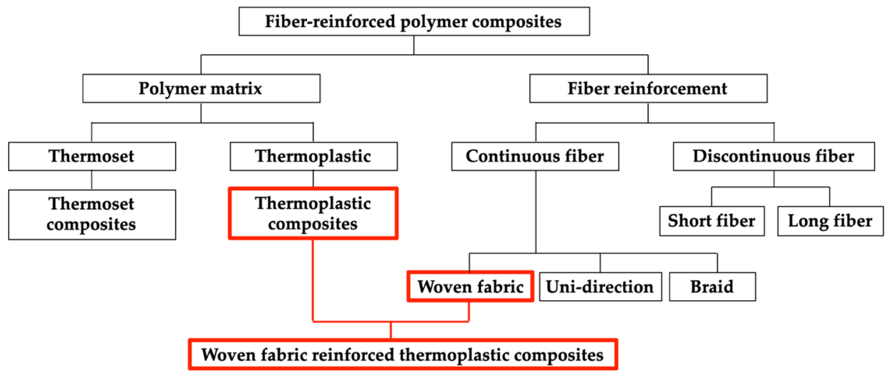
:1. Introduction
2. Materials and Experiments
2.1. Materials and Methods
2.2. Experiment
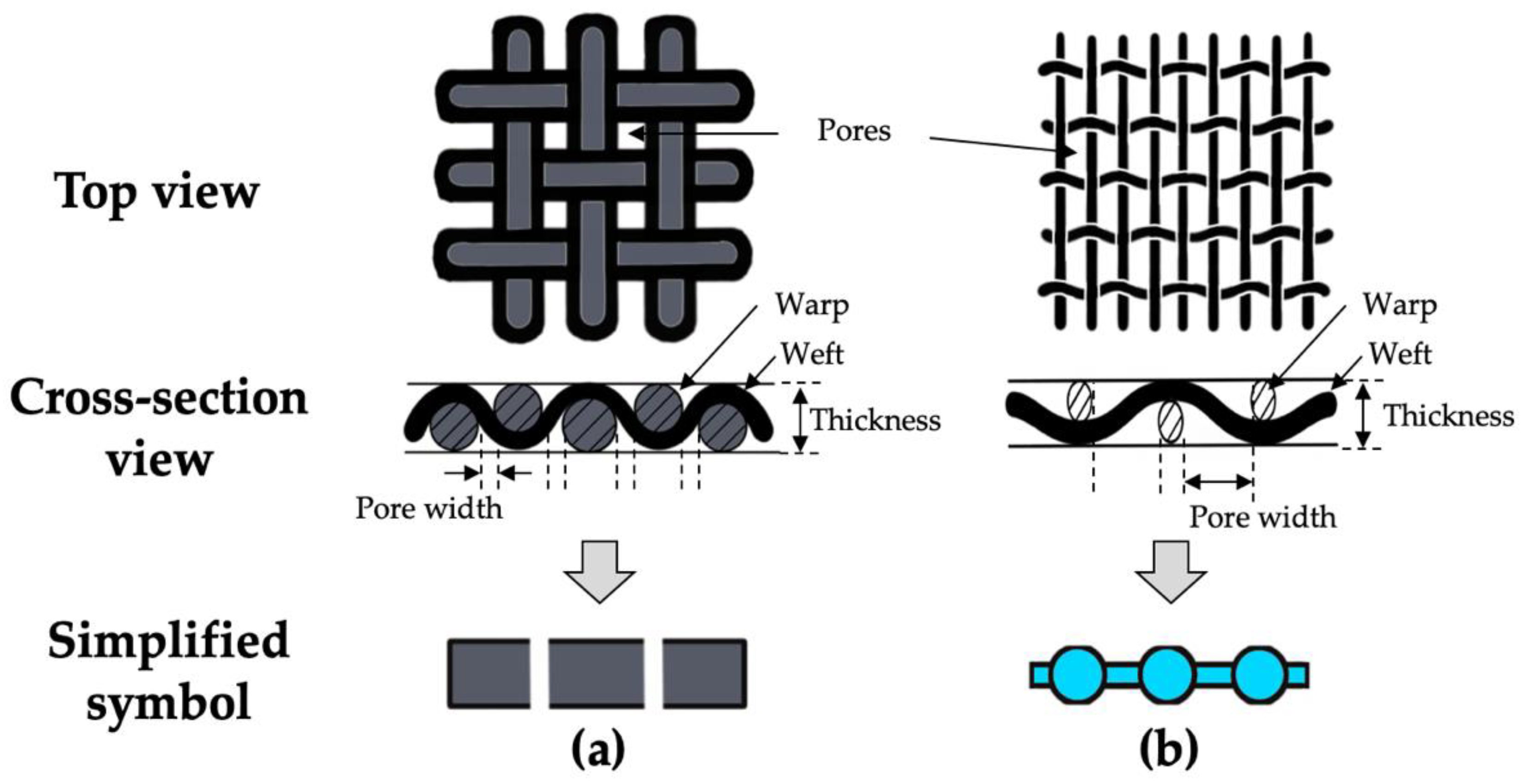
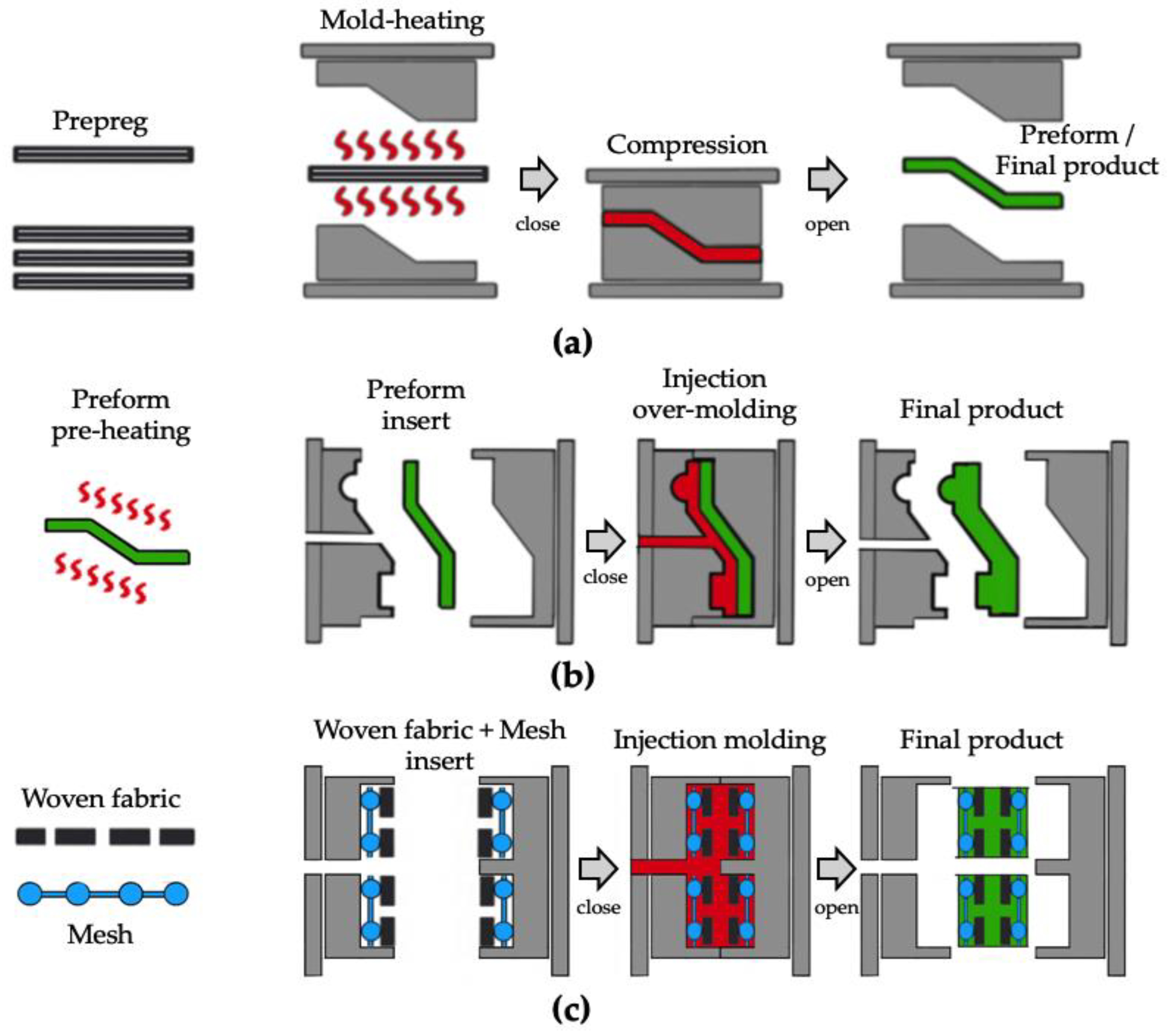
2.2.1. Impregnation Experiment
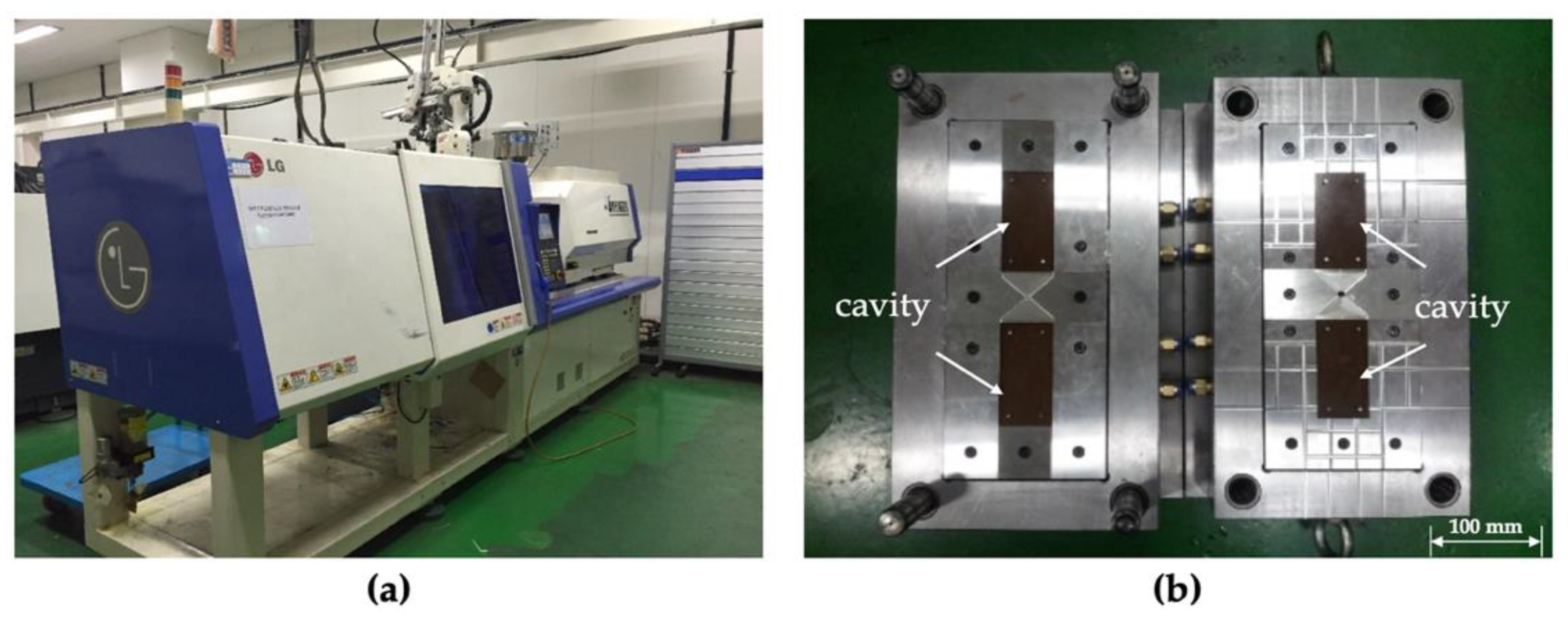
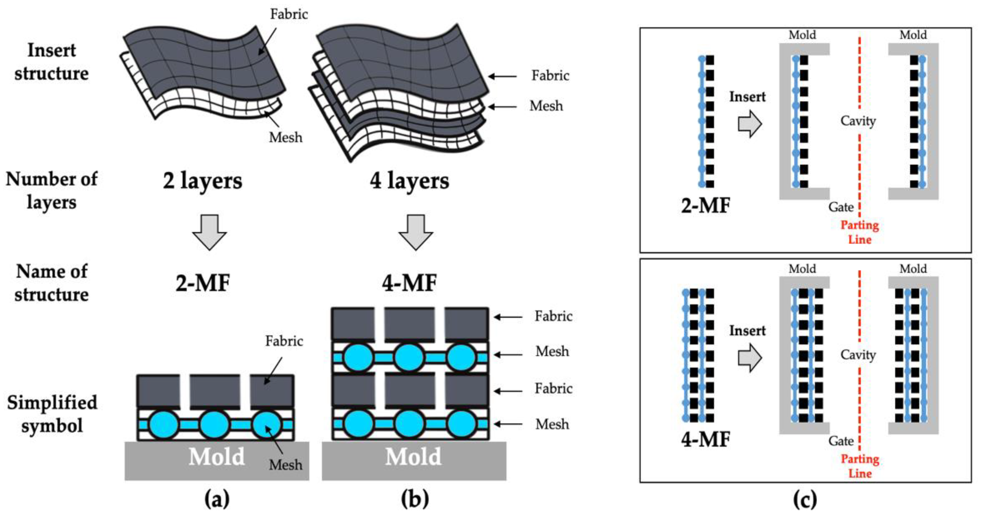
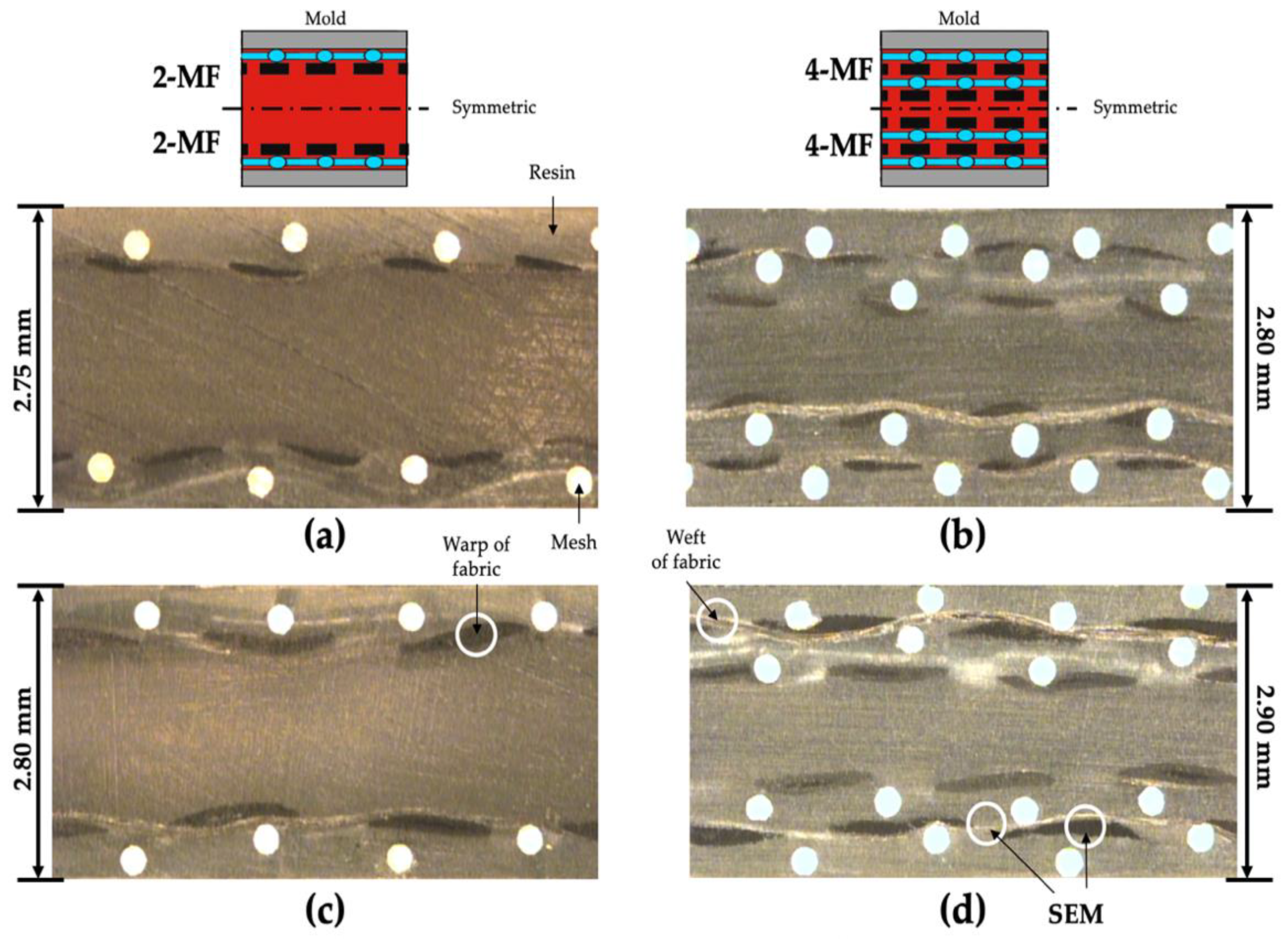
2.2.2. Injection Molding Experiment of Mesh-Inserted Composite
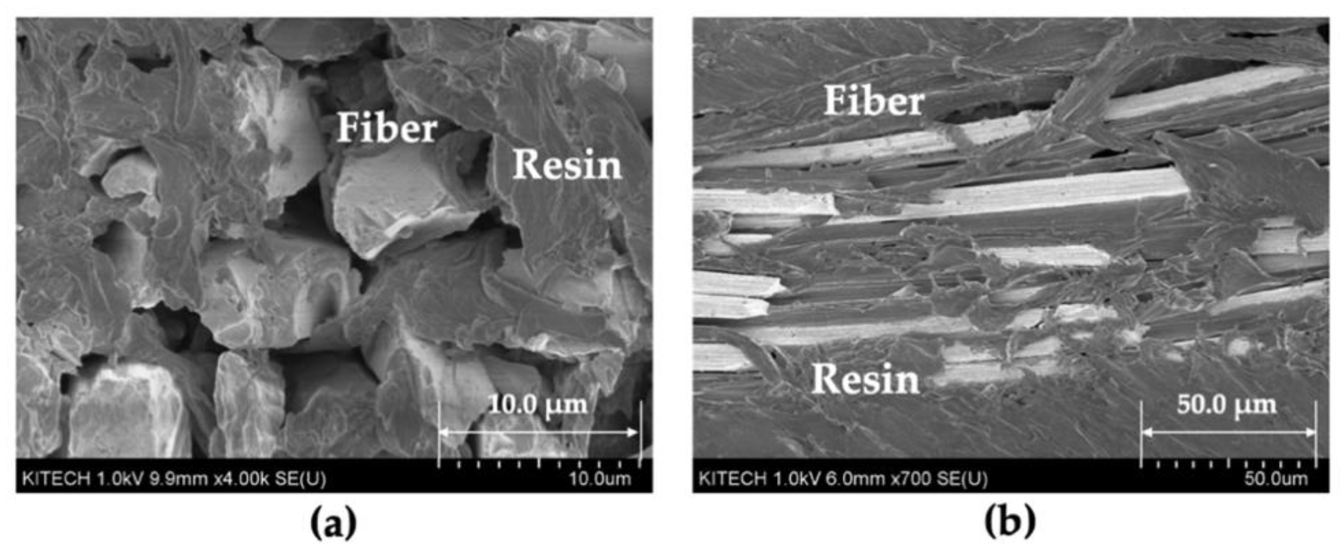
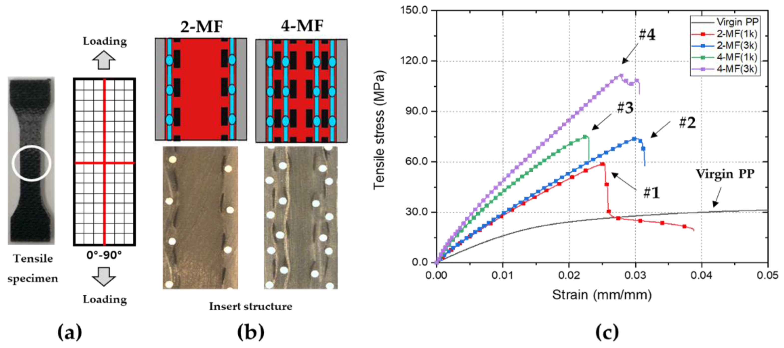
3. Results and Discussion
4. Conclusions
Author Contributions
Funding
Acknowledgments
Conflicts of Interest
References
- Rezaei, F.; Yunus, R.; Ibrahim, N.A.; Mahdi, E.S. Development of short carbon fiber reinforced polypropylene composite for car bonnet. Polym.-Plast. Technol. Eng. 2008, 47, 351–357. [Google Scholar] [CrossRef]
- Unterweger, C.; Bruggemann, O.; Furst, C. Synthetic fibers and thermoplastic short fiber reinforced polymers: Properties and characterization. Polym. Compos. 2014, 35, 227–236. [Google Scholar] [CrossRef]
- Yi, S. Development of multifunctional composites for aerospace application. In Multifunctionality of Polymer Composites; William Andrew Publishing: Oxford, UK, 2015; pp. 367–418. [Google Scholar]
- Holmes, M. High volume composites for automotive challenge. Reinf. Plast. 2017, 61, 294–298. [Google Scholar] [CrossRef]
- Kusic, D.; Bozic, U.; Monzon, M.; Bordon, P. Thermal and mechanical characterization of banana fiber reinforced composites for its application in injection molding. Materials 2020, 13, 3581. [Google Scholar] [CrossRef] [PubMed]
- Rahman, R.; Putra, S. Tensile properties of natural and synthetic fiber reinforced polymer composites. In Mechanical and Physical Testing of Biocomposite, Fiber Reinforced Composites and Hybrid Composites; Mohammad, J., Mohamed, T., Naheed, S., Eds.; Woodhead Publishing: Cambridge, UK, 2014; Volume 5, pp. 81–102. [Google Scholar]
- Rajak, D.; Pagar, D.; Menezes, P.; Linul, E. Fiber-reinforced polymer composites: Manufacturing, properties, and applications. Polymers 2019, 11, 1667. [Google Scholar] [CrossRef] [Green Version]
- Chung, D. Introduction to carbon composites. In Carbon Composites; Butterworth-Heinemann, University at Buffalo: Buffalo, NY, USA, 2017; Volume 2, pp. 88–160. [Google Scholar]
- Masuelli, M. Introduction of fibre-reinforced polymers-Polymer and composites: Concepts, properties and processes. In Fiber Reinforced Polymers—The Technology Applied for Concrete Repair; Intech: London, UK, 2013. [Google Scholar]
- Jawaid, M.; Khalil, H. Cellulosic/synthetic fibre reinforced polymer hybrid composites: A review. Carbohydr. Polym. 2011, 86, 1–18. [Google Scholar] [CrossRef]
- Altenbach, H.; Altenbach, J.; Kissing, W. Classification of composite materials. In Mechanics of Composite Structural Elements; Springer: Singapore, 2004; pp. 1–14. [Google Scholar]
- Carlsson, L. Thermoplastic composite materials. In Composite Material Series; Elsevier Science: Amsterdam, The Netherlands, 1991; Volume 7. [Google Scholar]
- Chang, I.; Lees, J. Recent development in thermoplastic composites: A review of matrix system and processing methods. Thermoplast. Compos. Mater. 1988, 1, 277–296. [Google Scholar] [CrossRef]
- Kada, D.; Koubaa, A.; Tabak, G.; Migneault, S.; Garnier, B.; Boudenne, A. Tensile properties, thermal conductivity, and thermal stability of short carbon fiber reinforced polypropylene composites. Polym. Compos. 2018, 39, 664–670. [Google Scholar] [CrossRef]
- Kager-Kocsis, J. Polypropylene structure, blends and composites. In Composites; Springer: Berlin/Heidelberg, Germany, 1995; Volume 3. [Google Scholar]
- Lim, S.H. High performance thermoplastic composites. Polym. Sci. Technol. 1995, 6, 451–458. [Google Scholar]
- Kim, S.T. Development trend for thermoplastic polymer composite. Polym. Sci. Technol. 2013, 24, 25–29. [Google Scholar]
- Schinner, G.; Brandt, J.; Richter, H. Recycling carbon-fiber-reinforced thermoplastic composites. Thermoplast. Compos. Mater. 1996, 9, 239–245. [Google Scholar] [CrossRef]
- Kim, J.; Lee, J. The effect of the melt viscosity and impregnation of a film on the mechanical properties of thermoplastic composites. Materials 2016, 9, 448. [Google Scholar] [CrossRef] [PubMed] [Green Version]
- Michaud, V.; Manson, J. Impregnation of compressible fiber mats with a thermoplastic resin. Part 1: Theory. Compos. Mater. 2001, 35, 1150–1173. [Google Scholar] [CrossRef]
- Seo, J.; Lee, W. A model of the resin impregnation in thermoplastic composites. Compos. Mater. 1991, 25, 1127–1142. [Google Scholar] [CrossRef]
- Gennaro, R.; Greco, A.; Maffezzoli, A. Micro- and macro-impregnation of fabrics using thermoplastic matrices. Thermoplast. Compos. Mater. 2013, 26, 527–543. [Google Scholar] [CrossRef]
- Henninger, F.; Friedrich, K. Thermoplastic filament winding with online-impregnation. Part A: Processing technology and operating efficiency. Compos. Part A Appl. Sci. Manuf. 2002, 33, 1479–1786. [Google Scholar] [CrossRef]
- Ishida, O.; Kitada, J.; Nunotani, K.; Uzawa, K. Impregnation and resin flow analysis during compression process for thermoplastic composite production. Adv. Compos. Mater. 2020, 30, 39–58. [Google Scholar] [CrossRef]
- Kobayashi, S.; Tsukada, T.; Morimoto, T. Resin impregnation behavior in carbon fiber reinforced polyamide 6 composite: Effects of yarn thickness, fabric lamination and sizing agent. Compos. Part A Appl. Sci. Manuf. 2017, 101, 283–289. [Google Scholar] [CrossRef]
- Gibson, A.; Manson, J. Impregnation technology for thermoplastic matrix composites. Compos. Manuf. 1992, 3, 223–233. [Google Scholar] [CrossRef]
- Bafna, S.S.; Baird, D.G. An impregnation model for the preparation of thermoplastic prepregs. Compos. Mater. 1992, 26, 683–707. [Google Scholar] [CrossRef]
- Chung, D.D.L. Polymer-matrix composites: Structure and processing. In Carbon Composites: Composites with Carbon Fibers, Nanofibers, and Nanotubes; Elsevier Science: Amsterdam, The Netherlands, 2017; pp. 161–217. [Google Scholar]
- Balasubramanian, K.; Sultan, M.T.H.; Rajeswari, N. Manufacturing techniques of composites for aerospace applications. In Sustainable Composites for Aerospace Applications; Woodhead Publishing: Sawston, UK; Cambridge, UK, 2018; pp. 55–67. [Google Scholar]
- Marissen, R.; Van Der Drift, L.; Sterk, J. Technology for rapid impregnation of fibre bundles with a molten thermoplastic polymer. Compos. Sci. Technol. 2000, 60, 2029–2034. [Google Scholar] [CrossRef]
- Minchenkov, K.; Vedernikov, A.; Safonov, A.; Akhatov, I. Thermoplastic pultrusion: A review. Polymers 2021, 13, 180. [Google Scholar] [CrossRef]
- Budiyantoro, C.; Rochardjo, H.; Nugroho, G. Effects of processing variables of extrusion-pultrusion method on the impregnation quality of thermoplastic composite filaments. Polymers 2020, 12, 2833. [Google Scholar] [CrossRef] [PubMed]
- Lunt, J.M.; Shortall, J.B. The effect of extrusion compounding on fibre degradation and strength properties in short glass fibre reinforced nylon 66. Plast. Rubber Process. 1980, 37, 108–111. [Google Scholar]
- Hyvarinen, M.; Jabeen, R.; Karki, T. The modeling of extrusion processes for polymer—A review. Polymers 2020, 12, 1306. [Google Scholar] [CrossRef] [PubMed]
- Wilczynski, K.; Buziak, K.; Wilczynski, K.; Lewandowski, A.; Nastaj, A. Computer modeling for single-screw extrusion of wood-plastic composites. Polymers 2018, 10, 295. [Google Scholar] [CrossRef] [PubMed] [Green Version]
- Wang, X.; Mayer, C.; Neitzel, M. Some issues on impregnation in manufacturing of thermoplastic composites by using a double belt. Polym. Compos. 1997, 18, 701–710. [Google Scholar] [CrossRef]
- Michaud, V.; Tornqvist, R.; Manson, J. Impregnation of compressible fiber mats with a thermoplastic resin, Part 2: Experiments. Compos. Mater. 2001, 35, 1174–1200. [Google Scholar] [CrossRef]
- Bernet, N.; Michaud, V.; Bourban, P.; Manson, J. Impregnation model for the consolidation of thermoplastic composites made from commingled yarns. Compos. Mater. 1999, 33, 751–772. [Google Scholar] [CrossRef]
- Hartness, J.T. Thermoplastic powder technology for advanced composite systems. Thermoplast. Compos. Mater. 1988, 1, 210–220. [Google Scholar] [CrossRef]
- Steggall-Murphy, C.; Simacek, P.; Advani, S.; Yarlagadda, S.; Walsh, S. A model for thermoplastic melt impregnation of fiber bundles during consolidation of powder-impregnated continuous fiber composites. Compos. Part A Appl. Sci. Manuf. 2010, 41, 93–100. [Google Scholar] [CrossRef]
- Friedrich, K.; Hou, M.; Krebs, J. Thermoforming of continuous fibre/thermoplastic composite sheets. In Composite Sheet Forming; Bhattacharyya, B., Ed.; Elsevier Science: Amsterdam, The Netherlands, 1997; Volume 11, pp. 91–162. [Google Scholar]
- Xiong, H.; Hamila, N.; Boisse, P. Consolidation modeling during thermoforming of thermoplastic composite prepregs. Materials 2019, 12, 2853. [Google Scholar] [CrossRef] [PubMed] [Green Version]
- Ruzek, R.; Krena, J.; Doubrava, R.; Tkadlec, J.; Kadlec, M.; Belsky, P. Optimal design and testing of a thermoplastic pressurized passenger door manufactured using thermoforming. Polymers 2021, 13, 3394. [Google Scholar] [CrossRef]
- Zheng, B.; Gao, X.; Li, M.; Deng, T.; Huang, Z.; Zhou, H.; Li, D. Formability and failure mechanisms of woven CF/PEEK composite sheet in solid-state thermoforming. Polymers 2019, 11, 966. [Google Scholar] [CrossRef] [PubMed] [Green Version]
- Aliyeva, N.; Sas, H.; Saner Okan, B. Recent developments on the overmolding process for the fabrication of thermosets and thermoplastic composites by the integration of nano/micron-scale reinforcements. Compos. Part A Appl. Sci. Manuf. 2021, 149, 106525. [Google Scholar] [CrossRef]
- Akkerman, R.; Bouwman, M.; Wijskamp, S. Analysis of the thermoplastic composite overmolding process: Interface strength. Front. Mater. 2020, 7, 27. [Google Scholar] [CrossRef]
- Ageyeva, T.; Sibikin, I.; Kovacs, J. A review of thermoplastic resin transfer molding: Process modeling and simulation. Polymers 2019, 11, 1555. [Google Scholar] [CrossRef] [PubMed] [Green Version]
- Murray, J.; Allen, T.; Bickerton, S.; Bajpai, A.; Gleich, K.; McCarthy, E.; Bradaigh, C. Thermoplastic RTM: Impact properties of anionically polymerised polyamide 6 composites for structural automotive parts. Energies 2021, 14, 5790. [Google Scholar] [CrossRef]
- Semperger, O.; Suplicz, A. The effect of the parameters of T-RTM on the properties of polyamide 6 prepared by in situ polymerization. Materials 2020, 13, 4. [Google Scholar] [CrossRef] [Green Version]
- Pantelelis, N.; Bistekos, E.; Emmerich, R.; Gerard, P.; Zoller, A.; Gallardo, R. Compression RTM of reactive thermoplastic composites using microwaves and cure monitoring. Procedia CIRP 2020, 85, 246–251. [Google Scholar] [CrossRef]
- Kim, S.; Park, C. Direct impregnation of thermoplastic melt into flax textile reinforcement for semi-structural composite parts. Ind. Crops Prod. 2017, 95, 651–663. [Google Scholar] [CrossRef]
- Studer, J.; Dransfeld, C.; Jauregui, C.J.; Keller, A.; Wink, M.; Masania, K.; Fiedler, B. Effect of fabric architecture, compaction and permeability on through thickness thermoplastic melt impregnation. Compos. Part A Appl. Sci. Manuf. 2019, 122, 45–53. [Google Scholar] [CrossRef]
- Kitayama, S.; Hashimoto, S.; Yakano, M.; Yamazaki, Y.; Kubo, Y.; Aiba, S. Multi-objective optimization for minimizing weldline and cycle time using variable injection velocity and variable pressure profile in plastic injection molding. Adv. Manuf. Technol. 2020, 107, 3351–3361. [Google Scholar] [CrossRef]
- Giang, N.; Minh, P.; Son, T.; Uyen, T.; Hai, N.; Dang, H. Study on external gas-assisted mold temperature control with the assistance of a flow focusing device in the injection molding process. Materials 2021, 14, 965. [Google Scholar] [CrossRef]
- Zhao, N.; Lian, J.; Wang, P.; Xu, Z. Recent progress in minimizing the warpage and shrinkage deformations by the optimization of process parameters in plastic injection molding: A review. Adv. Manuf. Technol. 2022. [Google Scholar] [CrossRef]
- Carrupt, M.; Piedade, A. Modification of the cavity of plastic injection molds: A brief review of materials and influence on the cooling rates. Materials 2021, 14, 7249. [Google Scholar] [CrossRef]
- Alvarado-Iniesta, A.; Cuate, O.; Schutze, O. Multi-objective and many objective design of plastic injection molding process. Adv. Manuf. Technol. 2019, 102, 3165–3180. [Google Scholar] [CrossRef]
- Zhou, H.; Zhang, S.; Wang, Z. Multi-objective optimization of process parameters in plastic injection molding using a differential sensitivity fusion method. Adv. Manuf. Technol. 2021, 114, 423–449. [Google Scholar] [CrossRef]
- Kuo, C.; Yang, X. Optimization of direct metal printing process parameters for plastic injection mold with both gas permeability and mechanical properties using design of experiments approach. Adv. Manuf. Technol. 2020, 109, 1219–1235. [Google Scholar] [CrossRef]
- Loaldi, D.; Piccolo, L.; Brwon, E.; Tosello, G.; Shemelya, C.; Masato, D. Hybrid process chain for the integration of direct ink writing and polymer injection molding. Micromachines 2020, 11, 509. [Google Scholar] [CrossRef]
- Wang, J.; Mao, Q.; Chen, J. Effects of injection molding parameters on properties of insert-injection molded polypropylene single-polymer composites. Polymers 2022, 14, 23. [Google Scholar] [CrossRef]
- Fu, S.; Lauke, B.; Mader, E.; Yue, C.; Hu, X. Tensile properties of short-glass-fiber- and short-carbon-fiber-reinforced polypropylene composites. Compos. Part A Appl. Sci. Manuf. 2000, 31, 1117–1125. [Google Scholar] [CrossRef]
- Zhu, H.; Yang, Z.; Li, Q.; Li, M.; Wang, S.; Zhang, Z. Fiber distribution of long fiber reinforced polyamide and effect of fiber orientation on mechanical behavior. Polym. Compos. 2020, 41, 1531–1550. [Google Scholar] [CrossRef]
- Jeong, E.C.; Yoon, K.H.; Kim, J.S.; Lee, S.H. A study on the production of carbon fiber composites using injection-molding grade thermoplastic pellets. Trans. Mater. Process. 2016, 25, 402–408. [Google Scholar] [CrossRef] [Green Version]


| Property | Method | Value |
|---|---|---|
| Density | ASTM D1505 1 | 0.90 g/cm3 1 |
| Melt index (230 °C, 2.16 kg) | ASTM D1238 1 | 10 g/10 min 1 |
| Tensile modulus | ISO 527 2 | 1.82 GPa 2 |
| Tensile strength | ISO 527 2 | 32.0 MPa 2 |
| Heat deflection temperature (0.46 MPa) | ASTM D648 1 | 119.0 °C 1 |
| Type | Types of Yarn | Thickness (mm) | Density (Counts/in) | Porosity | Weight (g/m2) |
|---|---|---|---|---|---|
| Fabric A | Carbon 1k | 0.14 | 17.5 | 0.10 | 95 |
| Fabric B | Carbon 3k | 0.27 | 13.0 | 0.06 | 208 |
| Mesh | Aluminum (Al) | 0.50 | 18.0 | 0.65 | 174 |
| Item | Value |
|---|---|
| Screw diameter (mm) | 25.0 |
| Maximum injection stroke (mm) | 111.0 |
| Injection capacity (cm3) | 185.0 |
| Maximum injection speed (mm/s) | 350.0 |
| Maximum injection pressure (kgf/cm2) | 2600 |
| Maximum clamping force (ton) | 110 |
| Process Condition | Value |
|---|---|
| Melt temperature (°C) | 240 |
| Mold temperature (°C) | 50 |
| Injection time (s) | 1.0 |
| Injection Speed (mm/s) | 45.0 |
| Back pressure (MPa) | 5.0 |
| V/P switch over pressure (MPa) | 35.0 |
| Packing pressure (MPa) | 30.0 |
| Packing time (s) | 2.0 |
| Cooling time (s) | 50 |
| Total cycle time | Less than 1 min |
| Type of Structure | Case Number | Name of Composite | Type of Fabric | Fiber Volume Fraction (%) | Mesh Volume Fraction (%) |
|---|---|---|---|---|---|
| 2-MF | #1 | 2-MF (1k) | Fabric A (1k) | 4.0 | 4.9 |
| #2 | 2-MF (3k) | Fabric B (3k) | 8.4 | 4.7 | |
| 4-MF | #3 | 4-MF (1k) | Fabric A (1k) | 7.9 | 9.4 |
| #4 | 4-MF (3k) | Fabric B (3k) | 16.2 | 9.2 |
| Type of Structure | Case Number | Fiber Volume Fraction (%) | Name of Composite | Tensile Modulus (GPa) (%/Virgin) | Tensile Strength (MPa) (%/Virgin) |
|---|---|---|---|---|---|
| Matrix | - | - | Virgin PP | 1.82 ± 0.04 | 32.0 ± 0.3 |
| 2-MF | #1 | 4.0 | 2-MF (1k) | 3.58 ± 0.11 (197%) | 54.0 ± 3.3 (169%) |
| #2 | 8.4 | 2-MF (3k) | 4.35 ± 0.08 (239%) | 72.0 ± 1.6 (225%) | |
| 4-MF | #3 | 7.9 | 4-MF (1k) | 6.63 ± 0.18 (364%) | 68.3 ± 5.5 (213%) |
| #4 | 16.2 | 4-MF (3k) | 7.61 ± 0.14 (418%) | 108.4 ± 5.3 (339%) |
Publisher’s Note: MDPI stays neutral with regard to jurisdictional claims in published maps and institutional affiliations. |
© 2022 by the authors. Licensee MDPI, Basel, Switzerland. This article is an open access article distributed under the terms and conditions of the Creative Commons Attribution (CC BY) license (https://creativecommons.org/licenses/by/4.0/).
Share and Cite
Jeong, E.; Kim, Y.; Hong, S.; Yoon, K.; Lee, S. Innovative Injection Molding Process for the Fabrication of Woven Fabric Reinforced Thermoplastic Composites. Polymers 2022, 14, 1577. https://doi.org/10.3390/polym14081577
Jeong E, Kim Y, Hong S, Yoon K, Lee S. Innovative Injection Molding Process for the Fabrication of Woven Fabric Reinforced Thermoplastic Composites. Polymers. 2022; 14(8):1577. https://doi.org/10.3390/polym14081577
Chicago/Turabian StyleJeong, Euichul, Yongdae Kim, Seokkwan Hong, Kyunghwan Yoon, and Sunghee Lee. 2022. "Innovative Injection Molding Process for the Fabrication of Woven Fabric Reinforced Thermoplastic Composites" Polymers 14, no. 8: 1577. https://doi.org/10.3390/polym14081577
APA StyleJeong, E., Kim, Y., Hong, S., Yoon, K., & Lee, S. (2022). Innovative Injection Molding Process for the Fabrication of Woven Fabric Reinforced Thermoplastic Composites. Polymers, 14(8), 1577. https://doi.org/10.3390/polym14081577