
Molecular Simulation Study on Mechanical Properties of Microcapsule-Based Self-Healing Cementitious Materials


Abstract
:1. Introduction
2. Computational Methodology
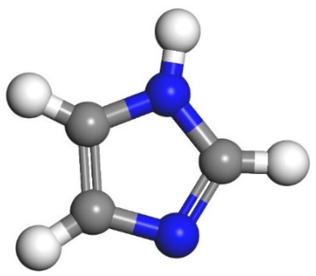
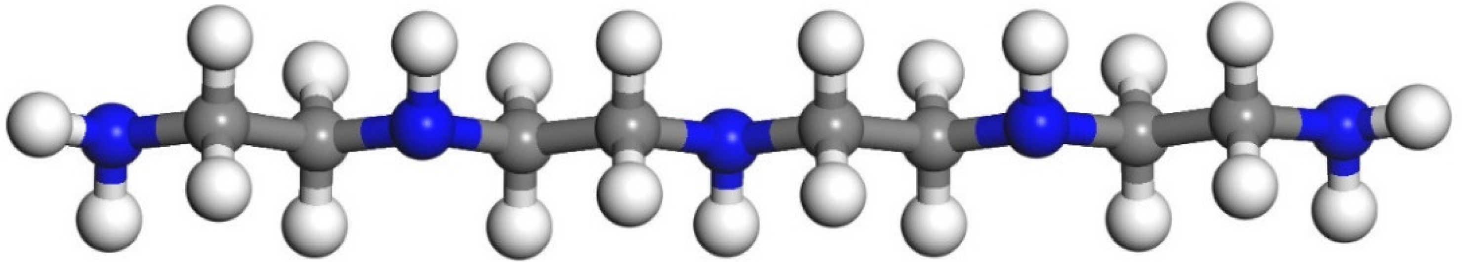
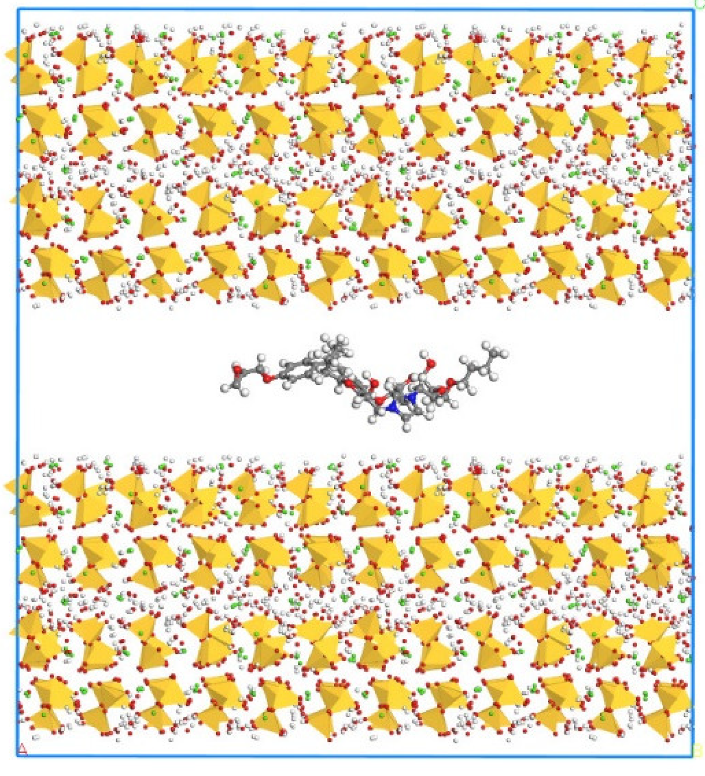
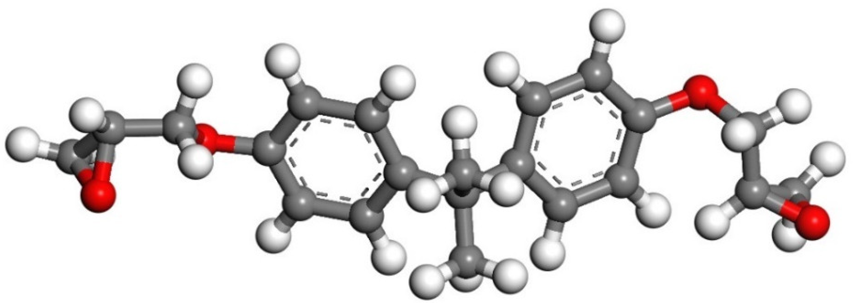
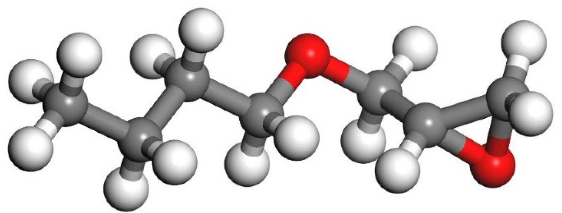
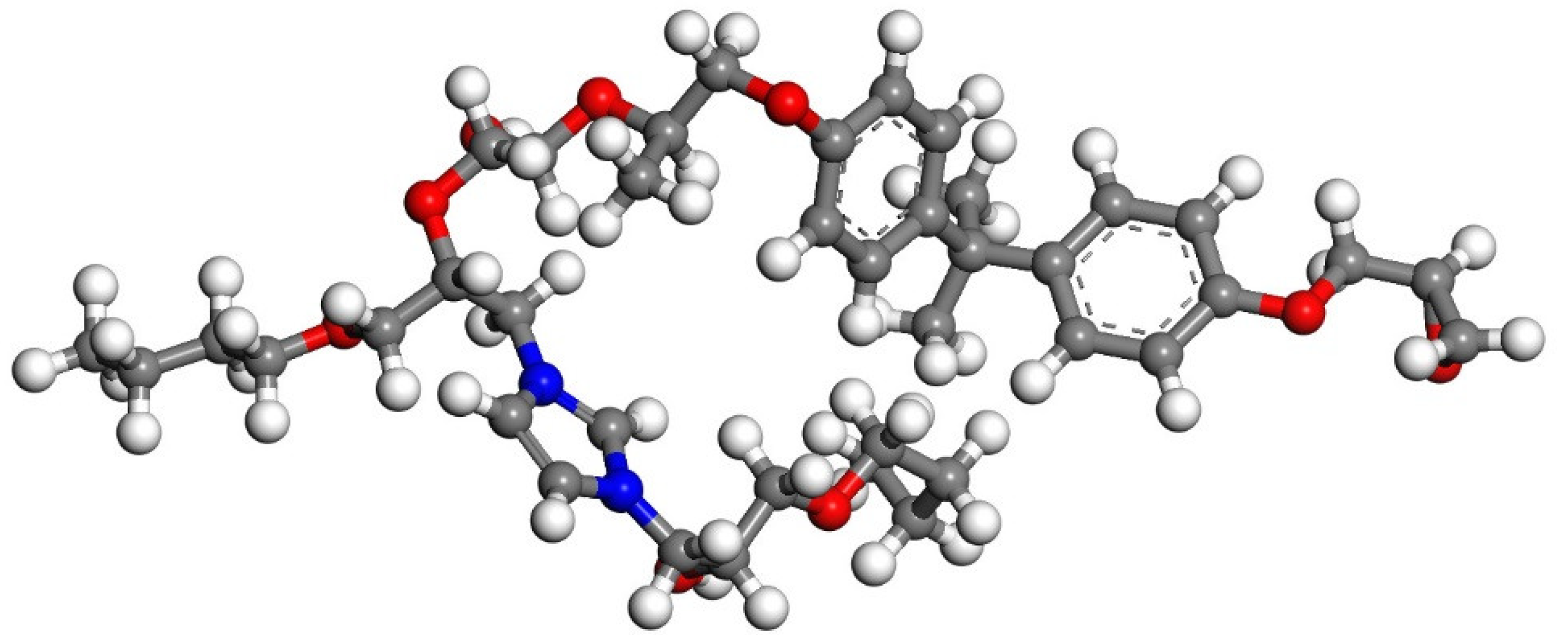
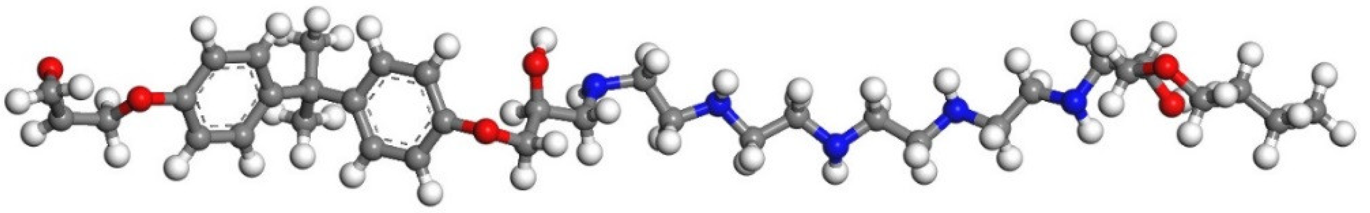
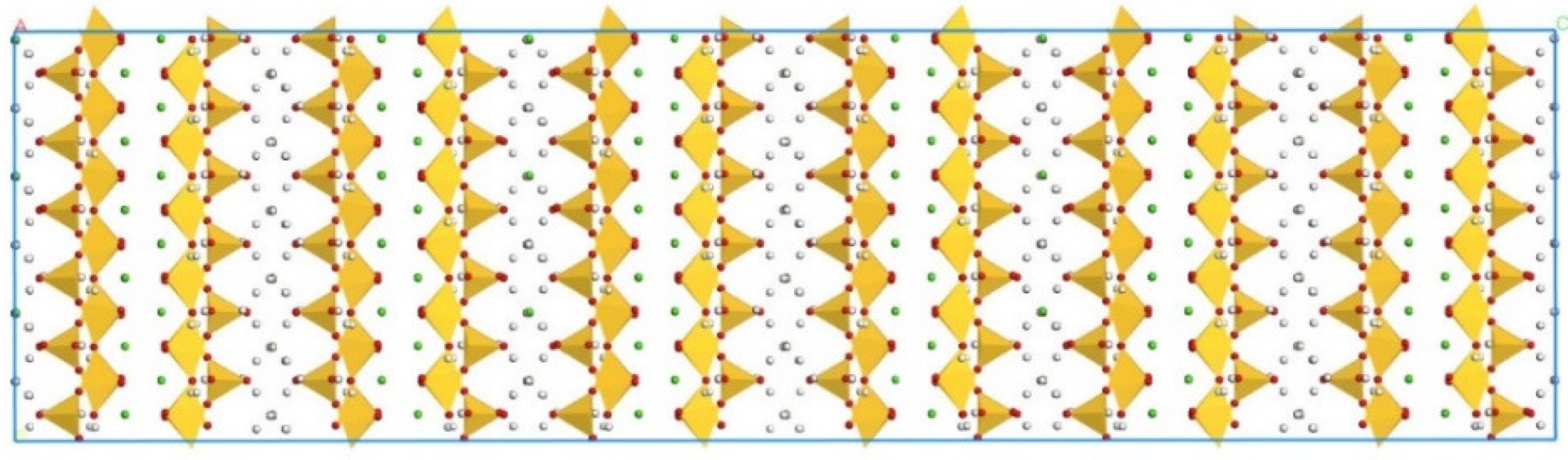
2.1. Model Construction
2.2. Uniaxial Tension Simulation
3. Results and Discussion
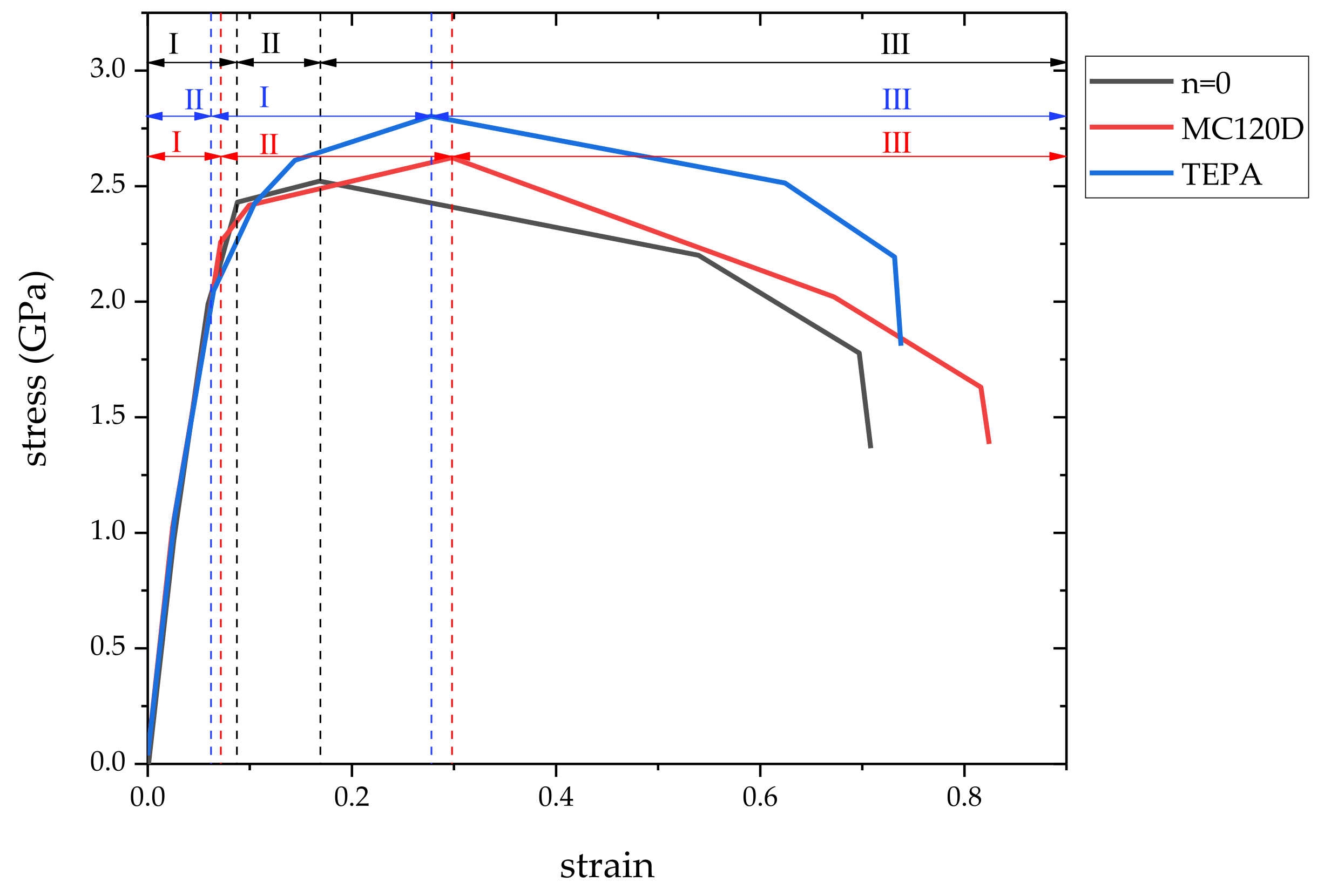
3.1. Stress-Strain Curve
3.2. Mechanical Properties
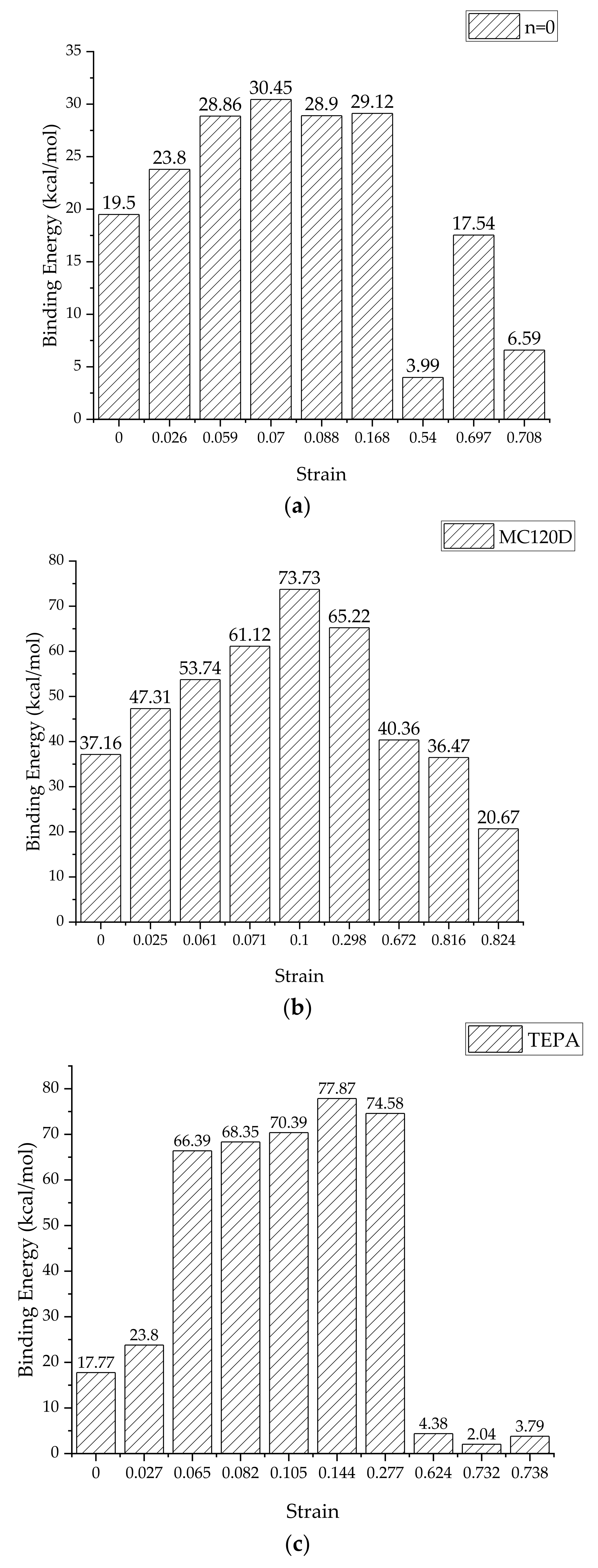
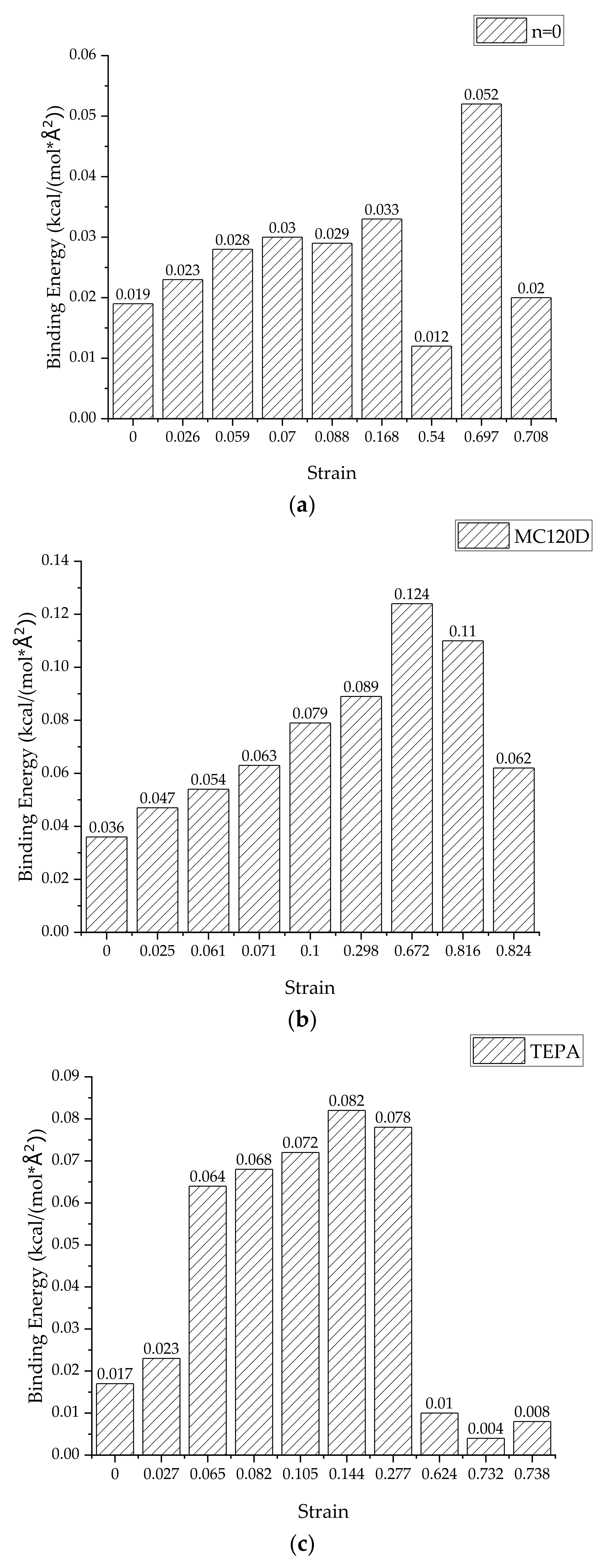
3.3. Binding Energy
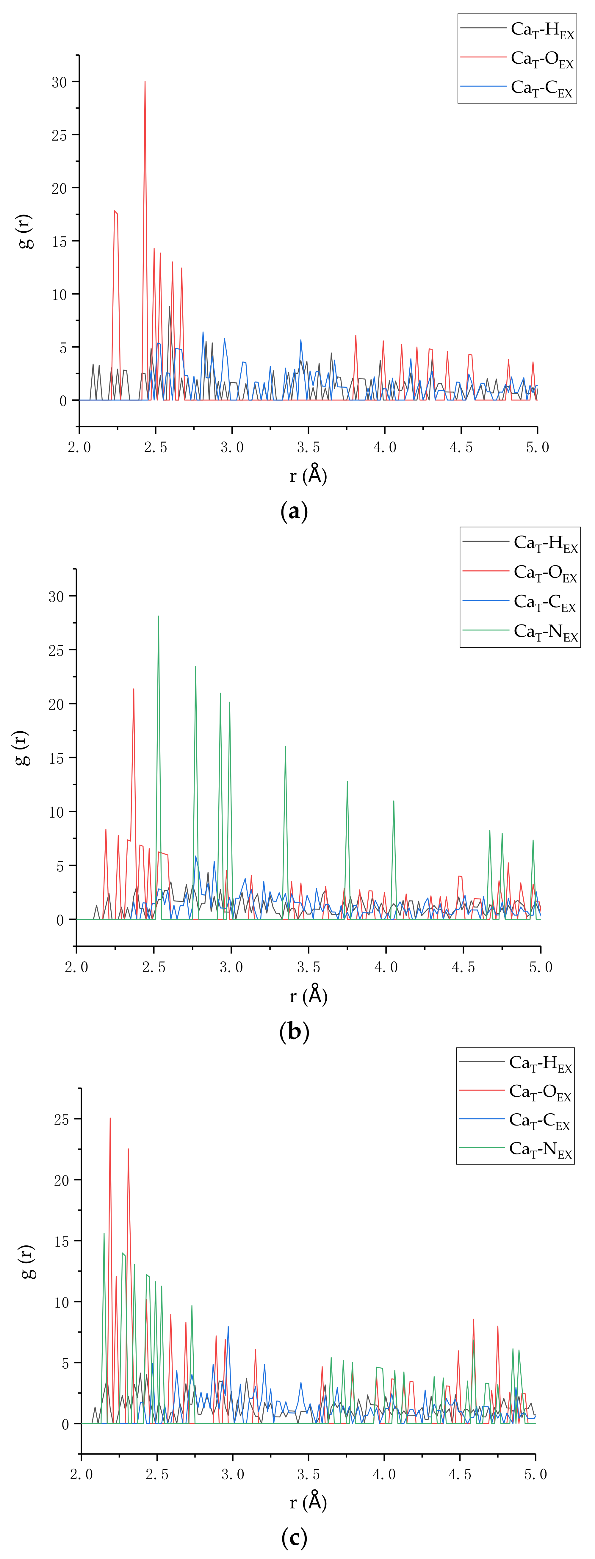
3.4. Radial Distribution Function
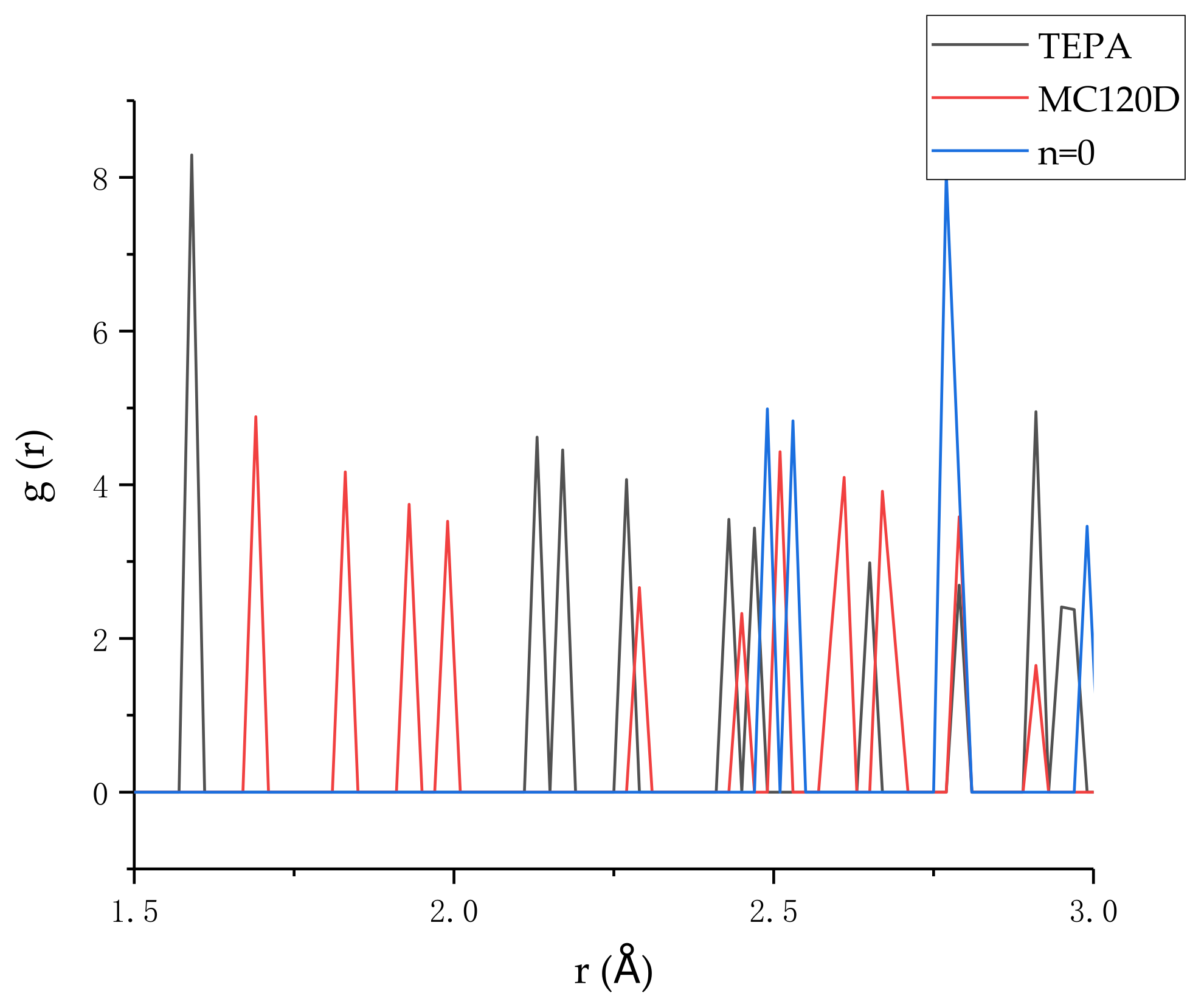
3.5. Hydrogen Bonding
4. Conclusions
- (1)
- The stress-strain curves proved that using a curing agent can increase the strength of the model, in which the highest strength was from TEPA.
- (2)
- The stress in the epoxy resin/C-S-H composite increases due to the increase of interface binding energy in the two stages before failure in the tensile process.
- (3)
- The reason why the model using TEPA as curing agent has the greatest strength should be attributed to the greater interaction between O and N atoms in the epoxy resin cured by TEPA and Ca ions in tobermorite, as well as stronger hydrogen bonding between tobermorite and epoxy resin.
- (4)
- The tensile simulation in this paper proves that the cured epoxy resin can enhance both the ductility and the strength of concrete, so that it can achieve self-healing function of concrete.
- (5)
- In this study, we mainly focus on studying the influence of curing agents on the repairing effect. In fact, there are still other factors that have not been considered (i.e., various amine compounds with a different number of amino groups), which should be studied in future.
Author Contributions
Funding
Data Availability Statement
Conflicts of Interest
References
- Bekas, D.G.; Tsirka, K.; Baltzis, D.; Paipetis, A.S. Self-healing materials: A review of advances in materials, evaluation, characterization and monitoring techniques. Compos. Part B 2016, 87, 92–119. [Google Scholar] [CrossRef]
- White, S.R.; Sottos, N.R.; Geubelle, P.H.; Moore, J.S.; Kessler, M.R.; Sriram, S.R.; Brown, E.N. Autonomic healing of polymer composites. Nature 2001, 409, 794–797. [Google Scholar] [CrossRef] [PubMed]
- Belie, N.D.; Tittelboom, K.V. Self-Healing in Cementitious Materials—A Review. Materials 2013, 6, 2182–2217. [Google Scholar]
- Zhang, M.; Xing, F.; Shi, K.Y.; Du, X.X. Study on Organic Microcapsule Based Self-Healing Cementitious Composite. Adv. Mater. Res. 2011, 1268, 764–767. [Google Scholar] [CrossRef]
- Wang, X.; Xing, F.; Zhang, M.; Han, N.; Qian, Z. Experimental Study on Cementitious Composites Embedded with Organic Microcapsules. Materials 2013, 6, 4064–4081. [Google Scholar] [CrossRef]
- Wang, X.; Zhang, J.; Han, R.; Han, N.; Xing, F. Evaluation of damage and repair rate of self-healing microcapsule-based cementitious materials using electrochemical impedance spectroscopy. J. Clean. Prod. 2019, 235, 966–976. [Google Scholar] [CrossRef]
- Blaiszik, B.J.; Kramer, S.L.B.; Olugebefola, S.C.; Moore, J.S.; Sottos, N.R.; White, S.R. Self-Healing Polymers and Composites. Annu. Rev. Mater. Res. 2010, 40, 179–211. [Google Scholar] [CrossRef]
- Wang, X.; Huang, Y.; Huang, Y.; Zhang, J.; Fang, C.; Yu, K.; Chen, Q.; Li, T.; Han, R.; Yang, Z. Laboratory and field study on the performance of microcapsule-based self-healing concrete in tunnel engineering. Constr. Build. Mater. 2019, 220, 90–101. [Google Scholar] [CrossRef]
- Sun, D.; Wenxu, M.; Jikun, M.; Yan, J.; Qianjin, M.; Yali, W.; Jianfeng, W.; Lan, M.; Wang, Z.; Cui, S.; et al. The synthesis of DMTDA microcapsules and investigation of self-healing cement paste through an isocyanate-amine system. Cem. Concr. Compos. 2021, 122, 104132. [Google Scholar] [CrossRef]
- Perez, G.; Erkizia, E.; Gaitero, J.J.; Kaltzakorta, I.; Jiménez, I.; Guerrero, A. Synthesis and characterization of epoxy encapsulating silica microcapsules and amine functionalized silica nanoparticles for development of an innovative self-healing concrete. Mater. Chem. Phys. 2015, 165, 39–48. [Google Scholar] [CrossRef]
- Wang, C.; Bu, Y.; Guo, S.; Lu, Y.; Sun, B.; Shen, Z. Self-healing cement composite: Amine- and ammonium-based pH-sensitive superabsorbent polymers. Cem. Concr. Compos. 2019, 96, 154–162. [Google Scholar] [CrossRef]
- Han, T.; Wang, X.; Li, D.; Li, D.; Xing, F.; Ren, J.; Han, N. Stress-strain behaviour and pore structure of microcapsule-based self-healing cementitious composite under triaxial tests. Constr. Build. Mater. 2020, 241, 118009. [Google Scholar] [CrossRef]
- Wang, X.F.; Han, R.; Tao, J.; Han, T.L.; Zhu, G.M.; Tang, J.N.; Han, N.X.; Xing, F. Identification of mechanical parameters of urea-formaldehyde microcapsules using finite-element method. Compos. Part B Eng. 2019, 158, 249–258. [Google Scholar] [CrossRef]
- Shalchy, F.; Rahbar, N. Nanostructural Characteristics and Interfacial Properties of Polymer Fibers in Cement Matrix. Acs Appl. Mater. Interfaces 2015, 7, 17278. [Google Scholar] [CrossRef] [PubMed]
- Rouhi, S.; Atfi, A. Molecular Dynamics Simulations of Adsorption of Polymer Chains on the Surface of BmNn Graphyne-Like Monolayers. Braz. J. Phys. 2017, 47, 239–267. [Google Scholar] [CrossRef]
- Fan, D.; Yang, S. Mechanical properties of C-S-H globules and interfaces by molecular dynamics simulation. Constr. Build. Mater. 2018, 176, 573–582. [Google Scholar] [CrossRef] [Green Version]
- Sadat, M.R.; Muralidharan, K.; Zhang, L. Reactive molecular dynamics simulation of the mechanical behavior of sodium aluminosilicate geopolymer and calcium silicate hydrate composites. Comput. Mater. Sci. 2018, 150, 500–509. [Google Scholar] [CrossRef]
- Ching, W.Y.; Poudel, L.; San, S.; Baral, K. Interfacial Interaction between Suolunite Crystal and Silica Binding Peptide for Novel Bioinspired Cement. ACS Comb. Sci. 2019, 21, 794–804. [Google Scholar] [CrossRef]
- Alkhateb, H.; Al-Ostaz, A.; Cheng, H.D.; Li, X. Materials Genome for Graphene-Cement Nanocomposites. J. Nanomechanics Micromechanics 2013, 3, 67–77. [Google Scholar] [CrossRef]
- Du, J.; Bu, Y.; Shen, Z. Interfacial properties and nanostructural characteristics of epoxy resin in cement matrix. Constr. Build. Mater. 2018, 164, 103–112. [Google Scholar] [CrossRef]
- Oral, B.; Markus, J.B.; Denvid, L.; Chakrapan, T. Structural solution using molecular dynamics: Fundamentals and a case study of epoxy-silica interface. Int. J. Solids Struct. 2011, 48, 2131–2140. [Google Scholar]
- Jiang, F.; Yang, Q.; Wang, Y.; Wang, P.; Hou, D.; Jin, Z. Insights on the adhesive properties and debonding mechanism of CFRP/concrete interface under sulfate environment: From experiments to molecular dynamics. Constr. Build. Mater. 2020, 269, 121247. [Google Scholar] [CrossRef]
- Hou, D.; Yang, Q.; Wang, P.; Jin, Z.; Wang, M.; Zhang, Y.; Wang, X. Unraveling disadhesion mechanism of epoxy/CSH interface under aggressive conditions. Cem. Concr. Res. 2021, 146, 106489. [Google Scholar] [CrossRef]
- Wang, X.; Xie, W.; Li, T.; Ren, J.; Zhu, J.; Han, N.; Xing, F. Molecular Dynamics Study on Mechanical Properties of Interface between Urea-Formaldehyde Resin and Calcium-Silicate-Hydrates. Materials 2020, 13, 4054. [Google Scholar] [CrossRef]
- Wang, X.; Xie, W.; Ren, J.; Zhu, J.; Li, L.; Xing, F. Interfacial Binding Energy between Calcium-Silicate-Hydrates and Epoxy Resin: A Molecular Dynamics Study. Polymers 2021, 13, 1683. [Google Scholar] [CrossRef]
- Zhang, M. A Study on Microcapsule Based Self-Healing Method and Mechanism for Cementitious Composites; Central South University: Changsha, China, 2013. [Google Scholar]
- Ooi, S.K.; Cook, W.D.; Simon, G.P.; Such, C.H. DSC studies of the curing mechanisms and kinetics of DGEBA using imidazole curing agents. Polymer 2000, 41, 3639–3649. [Google Scholar] [CrossRef]
- Manzano, H.; Masoero, E.; Lopez-Arbeloa, I.; Jennings, H.M. Shear deformations in calcium silicate hydrates. Soft Matter 2013, 9, 7333–7341. [Google Scholar] [CrossRef]
- Bonaccorsi, E.; Merlino, S.; Kampf, A.R. The Crystal Structure of Tobermorite 14 Å (Plombierite), a C–S–H Phase. J. Am. Ceram. Soc. 2005, 88, 505–512. [Google Scholar] [CrossRef]
- Nonat, A. The structure and stoichiometry of C-S-H. Cem. Concr. Res. 2004, 34, 1521–1528. [Google Scholar] [CrossRef]
- Sun, H. COMPASS: An ab Initio Force-Field Optimized for Condensed-Phase ApplicationsOverview with Details on Alkane and Benzene Compounds. J. Phys. Chem. B 1998, 102, 7338–7364. [Google Scholar] [CrossRef]
- Sun, H.; Ren, P.; Fried, J.R. The COMPASS force field: Parameterization and validation for phosphazenes. Comput. Theor. Polym. Sci. 1998, 8, 229–246. [Google Scholar] [CrossRef]
- Tavakoli, D.; Tarighat, A. Molecular dynamics study on the mechanical properties of Portland cement clinker phases. Comput. Mater. Sci. 2016, 119, 65–73. [Google Scholar] [CrossRef]
- Wu, W.; Al-Ostaz, A.; Cheng, A.H.D.; Song, C.R. Computation of Elastic Properties of Portland Cement Using Molecular Dynamics. J. Nanomechanics Micromechanics 2011, 1, 84–90. [Google Scholar] [CrossRef]
- Hajilar, S.; Shafei, B. Nano-scale investigation of elastic properties of hydrated cement paste constituents using molecular dynamics simulations. Comput. Mater. Sci. 2015, 101, 216–226. [Google Scholar] [CrossRef]
- Hou, D.; Zhu, Y.; Lu, Y.; Li, Z. Mechanical properties of calcium silicate hydrate (C–S–H) at nano-scale: A molecular dynamics study. Mater. Chem. Phys. 2014, 146, 503–511. [Google Scholar] [CrossRef]
- Kanellopoulos, A.; Giannaros, P.; Al-Tabbaa, A. The effect of varying volume fraction of microcapsules on fresh, mechanical and self-healing properties of mortars. Constr. Build. Mater. 2016, 122, 577–593. [Google Scholar] [CrossRef]
- Li, Y.; Zhang, G.; Wang, Z.; Guan, Z. Experimental-computational approach to investigate compressive strength of magnesium phosphate cement with nanoindentation and finite element analysis. Constr. Build. Mater. 2018, 190, 414–426. [Google Scholar] [CrossRef]
- Manzano, H.; Dolado, J.S.; Ayuela, A. Elastic properties of the main species present in Portland cement pastes. Acta Mater. 2008, 57, 1666–1674. [Google Scholar] [CrossRef]
- Alizadeh, R.; Beaudoin, J.J.; Raki, L. Mechanical properties of calcium silicate hydrates. Mater. Struct. 2011, 44, 13–28. [Google Scholar] [CrossRef] [Green Version]
- Mori, T.; Tanaka, K. Average stress in matrix and average elastic energy of materials with misfitting inclusions. Acta Metall. 1973, 21, 571–574. [Google Scholar] [CrossRef]
- Du, J.; Bu, Y.; Guo, S.; Tian, L.; Shen, Z. Effects of epoxy resin on ground-granulated blast furnace slag stabilized marine sediments. RSC Adv. 2017, 7, 36460–36472. [Google Scholar] [CrossRef] [Green Version]
- Chen, S.J.; Li, C.Y.; Wang, Q.; Duan, W.H. Reinforcing mechanism of graphene at atomic level: Friction, crack surface adhesion and 2D geometry. Carbon 2017, 114, 557–565. [Google Scholar] [CrossRef]
- Rapaport, D.C. The Art of Molecular Dynamics Simulaton; Cambridge University Press: Cambridge, UK, 2004. [Google Scholar]
- Sindu, B.S.; Sasmal, S. Molecular dynamics simulations for evaluation of surfactant compatibility and mechanical characteristics of carbon nanotubes incorporated cementitious composite. Constr. Build. Mater. 2020, 253, 119190. [Google Scholar]
- Wang, J.; Kalinichev, A.G.; Kirkpatrick, R.J. Molecular modeling of water structure in nano-pores between brucite (001) surfaces1. Geochim. Et Cosmochim. Acta 2004, 68, 3351–3365. [Google Scholar] [CrossRef]


| Model | Failure Strain | Tensile Strength (GPa) |
|---|---|---|
| n = 0 | 0.17 | 2.52 |
| MC120D | 0.30 | 2.62 |
| TEPA | 0.28 | 2.80 |
| Model | Bulk Modulus (Variance) (K) | Shear Modulus (Variance) (G) | Young’s Modulus (Variance) (E) | ||
|---|---|---|---|---|---|
| X | Y | Z | |||
| n = 0 | 48.33 (0.11) | 20.61 (0.06) | 54.76 (2.07) | 70.24 (0.41) | 55.89 (2.34) |
| MC120D | 46.56 (0.00) | 18.18 (0.01) | 49.45 (0.00) | 64.69 (0.01) | 49.84 (0.00) |
| TEPA | 47.89 (0.33) | 21.19 (1.12) | 53.35 (0.72) | 70.40 (1.20) | 50.74 (0.83) |
| Model | Poisson’s Ratio | Young’s Modulus (GPa) |
|---|---|---|
| n = 0 | 0.31 | 54.14 |
| MC120D | 0.33 | 48.26 |
| TEPA | 0.31 | 55.41 |
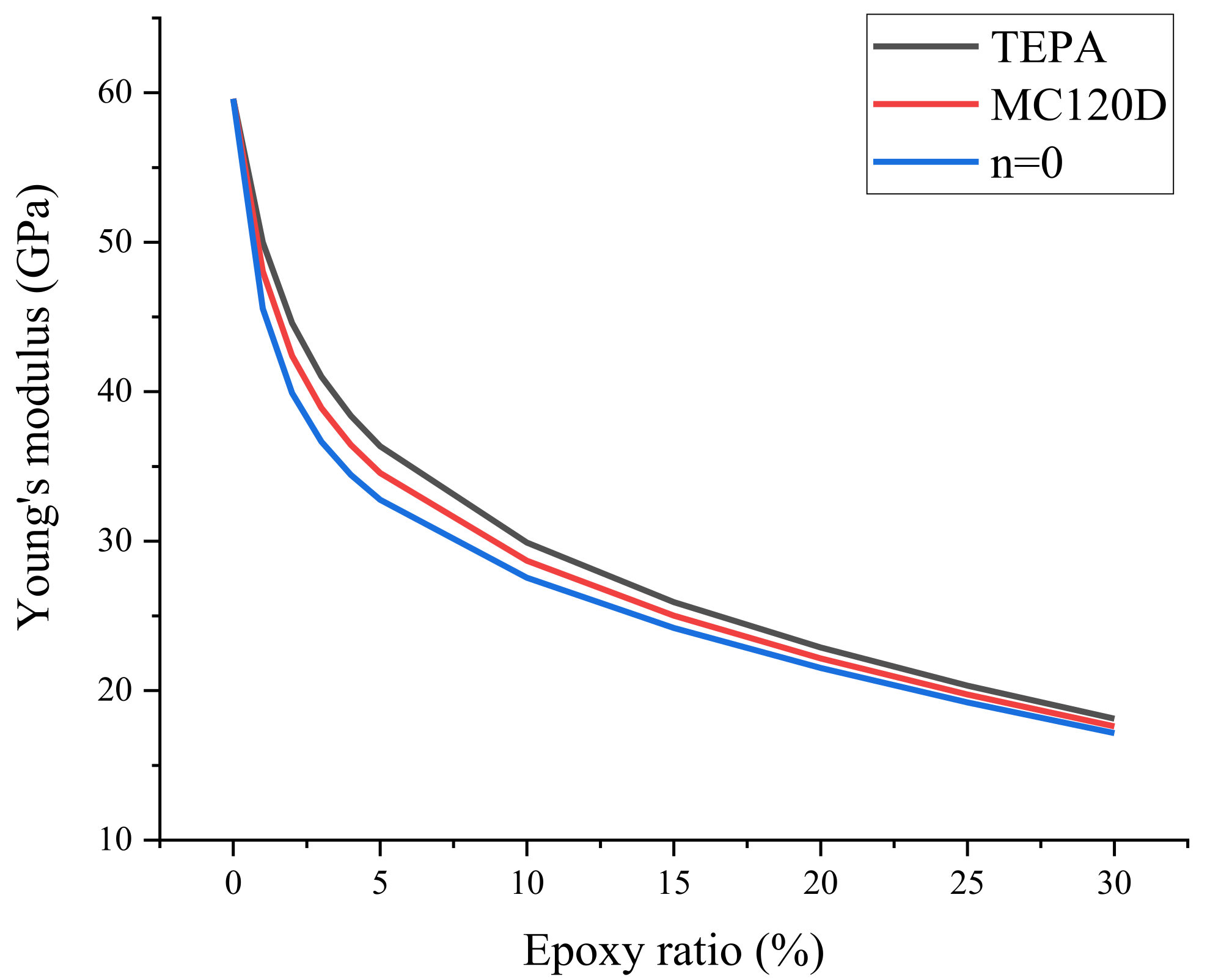
| Epoxy Ratio (%) | Young’s Modulus (GPa) | ||
|---|---|---|---|
| n = 0 | MC120D | TEPA | |
| 0 | 59.59 | 59.59 | 59.59 |
| 1 | 45.57 | 48.05 | 50.00 |
| 2 | 39.91 | 42.41 | 44.59 |
| 3 | 36.66 | 38.91 | 41.01 |
| 4 | 34.44 | 36.45 | 38.39 |
| 5 | 32.77 | 34.56 | 36.34 |
| 10 | 27.56 | 28.69 | 29.91 |
| 15 | 24.20 | 25.02 | 25.93 |
| 20 | 21.52 | 22.16 | 22.88 |
| 25 | 19.21 | 19.74 | 20.34 |
| 30 | 17.16 | 17.61 | 18.12 |
Publisher’s Note: MDPI stays neutral with regard to jurisdictional claims in published maps and institutional affiliations. |
© 2022 by the authors. Licensee MDPI, Basel, Switzerland. This article is an open access article distributed under the terms and conditions of the Creative Commons Attribution (CC BY) license (https://creativecommons.org/licenses/by/4.0/).
Share and Cite
Wang, X.; Xie, W.; Li, L.-y.; Zhu, J.; Xing, F. Molecular Simulation Study on Mechanical Properties of Microcapsule-Based Self-Healing Cementitious Materials. Polymers 2022, 14, 611. https://doi.org/10.3390/polym14030611
Wang X, Xie W, Li L-y, Zhu J, Xing F. Molecular Simulation Study on Mechanical Properties of Microcapsule-Based Self-Healing Cementitious Materials. Polymers. 2022; 14(3):611. https://doi.org/10.3390/polym14030611
Chicago/Turabian StyleWang, Xianfeng, Wei Xie, Long-yuan Li, Jihua Zhu, and Feng Xing. 2022. "Molecular Simulation Study on Mechanical Properties of Microcapsule-Based Self-Healing Cementitious Materials" Polymers 14, no. 3: 611. https://doi.org/10.3390/polym14030611
APA StyleWang, X., Xie, W., Li, L.-y., Zhu, J., & Xing, F. (2022). Molecular Simulation Study on Mechanical Properties of Microcapsule-Based Self-Healing Cementitious Materials. Polymers, 14(3), 611. https://doi.org/10.3390/polym14030611