
Boosting the Electrochemical Performance of Polyaniline by One-Step Electrochemical Deposition on Nickel Foam for High-Performance Asymmetric Supercapacitor


Abstract
:
1. Introduction
2. Experimental
2.1. Materials
2.2. Synthesis of Jute Sticks Derived Activated Carbon Nanosheets (JAC)
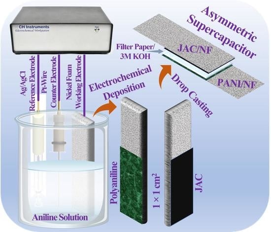
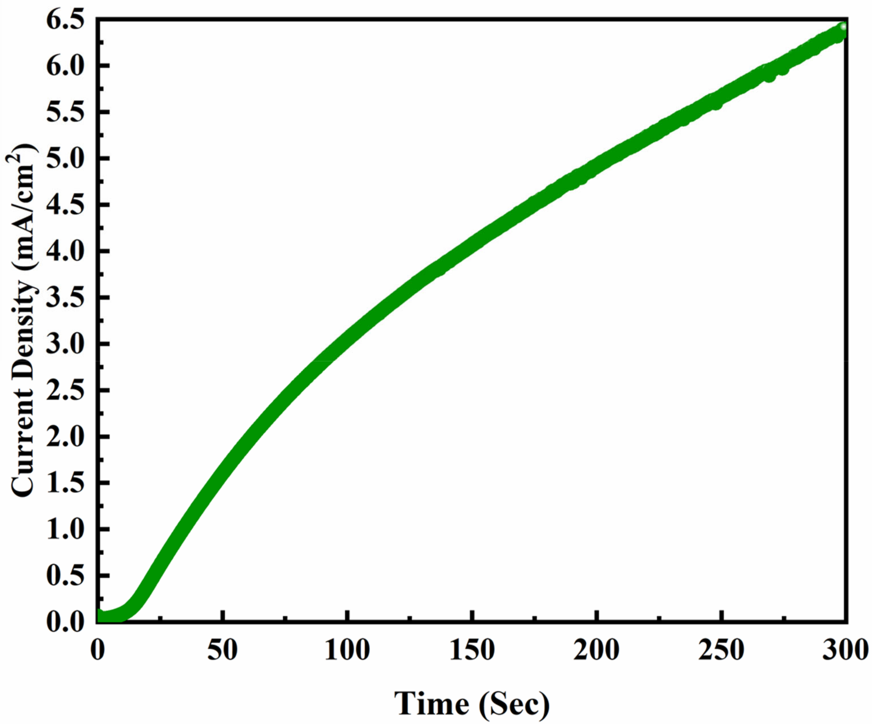
2.3. Electrochemical Deposition of PANI on Nickel Foam (PANI/NF)
2.4. Characterization of the As-Synthesized Electrodeposited PANI/NF
2.5. Fabrication of Working Electrodes and ASC Cell Assembly
2.6. Electrochemical Measurements
3. Results and Discussion
3.1. Morphological and Structural Analysis of the Bare NF and Electrodeposited PANI/NF
3.1.1. FESEM
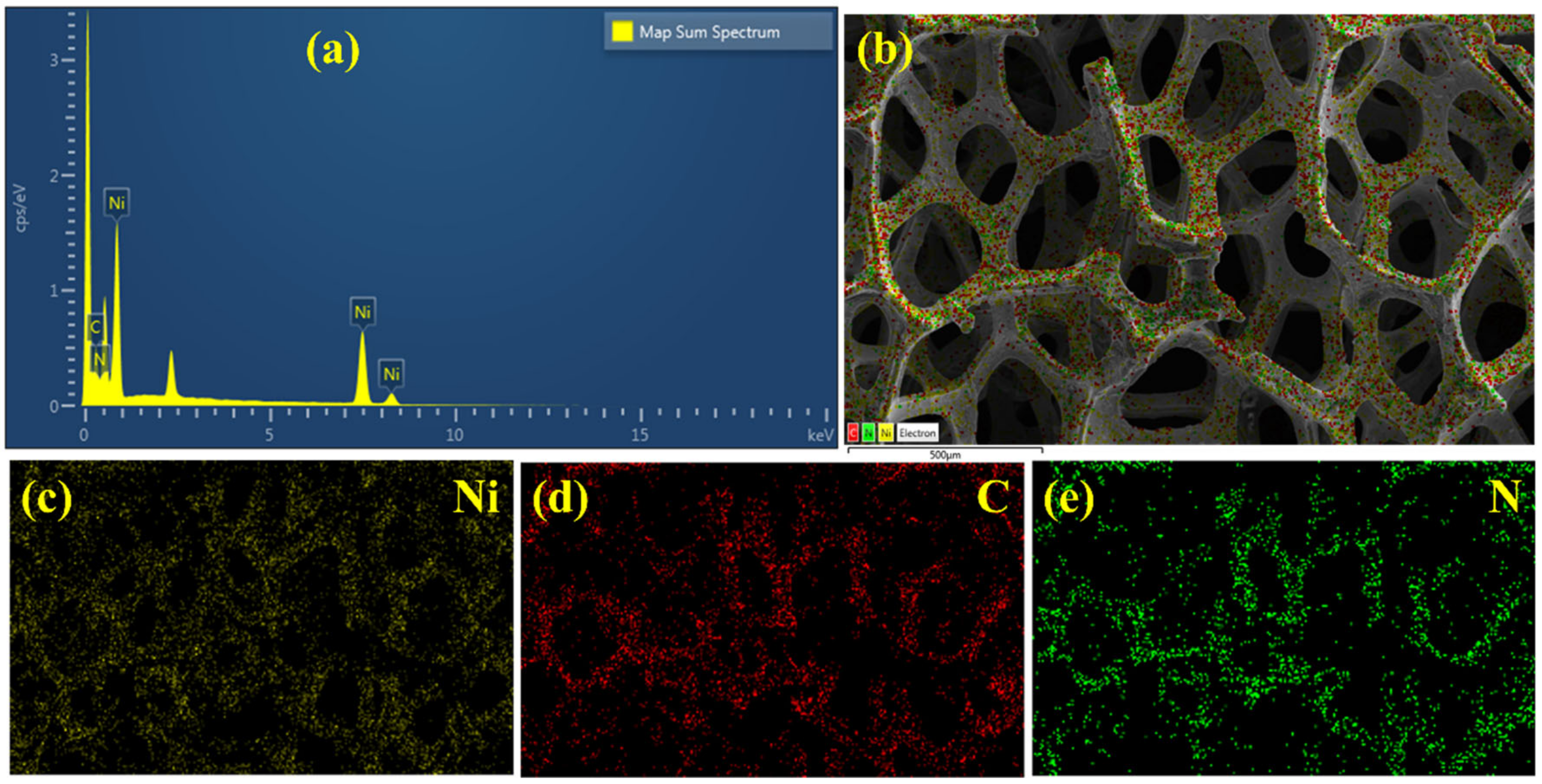
3.1.2. EDAX and Elemental Mapping
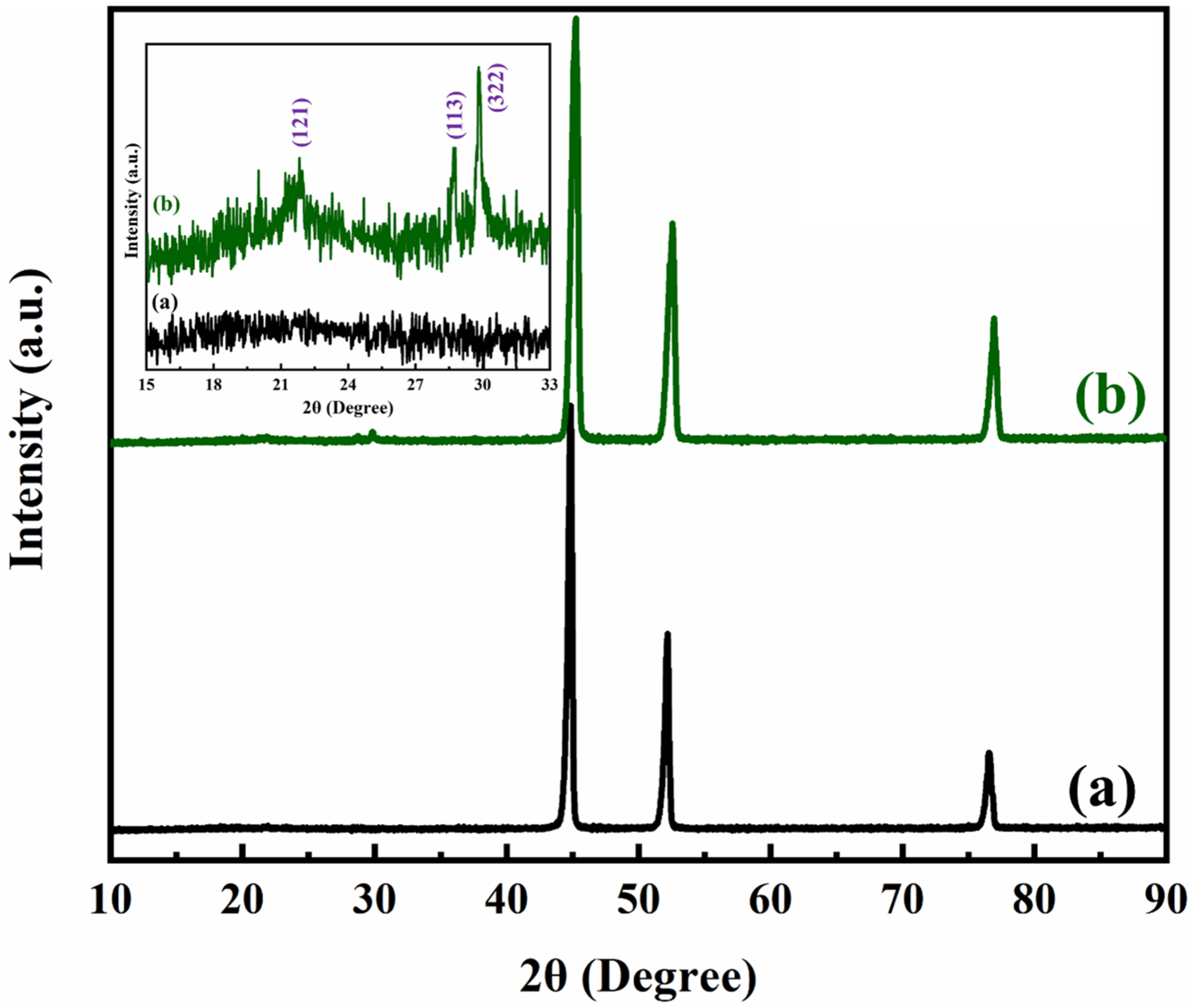
3.1.3. XRD
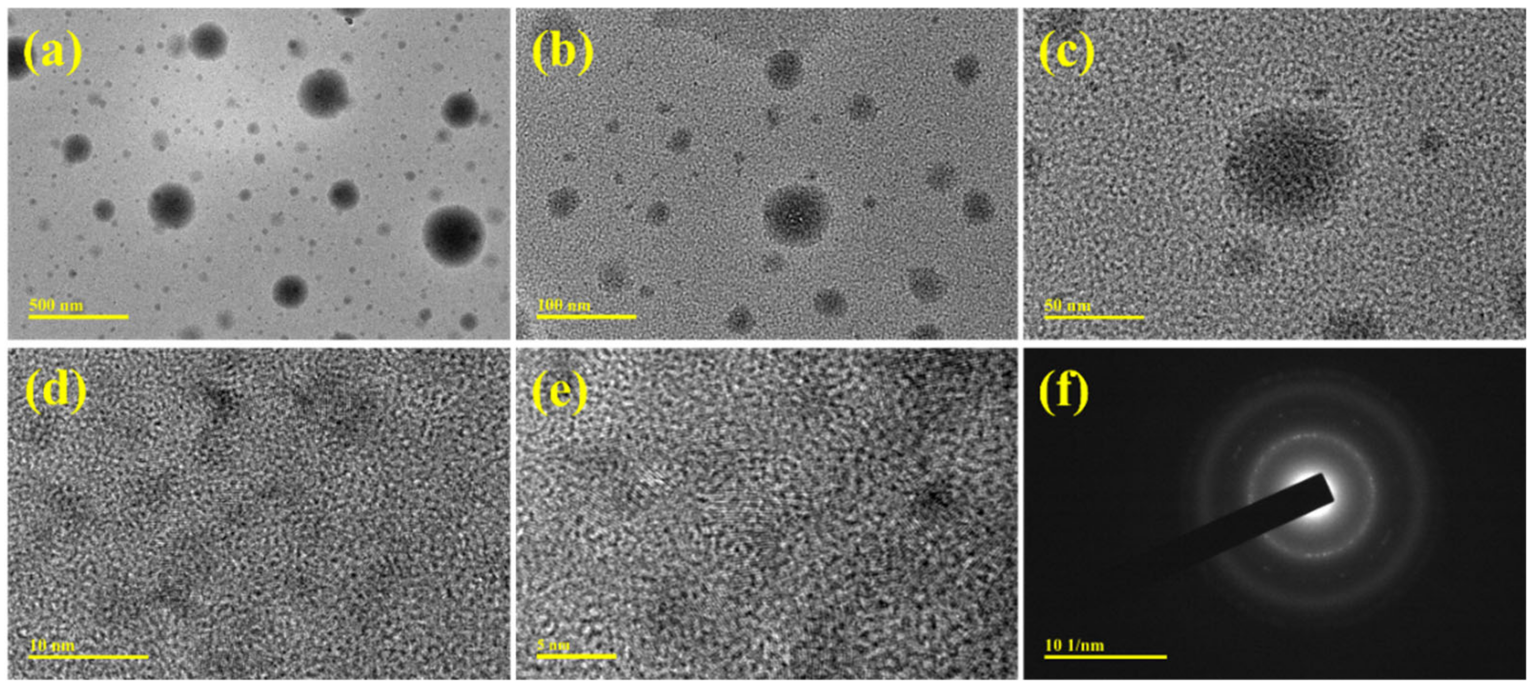
3.1.4. TEM
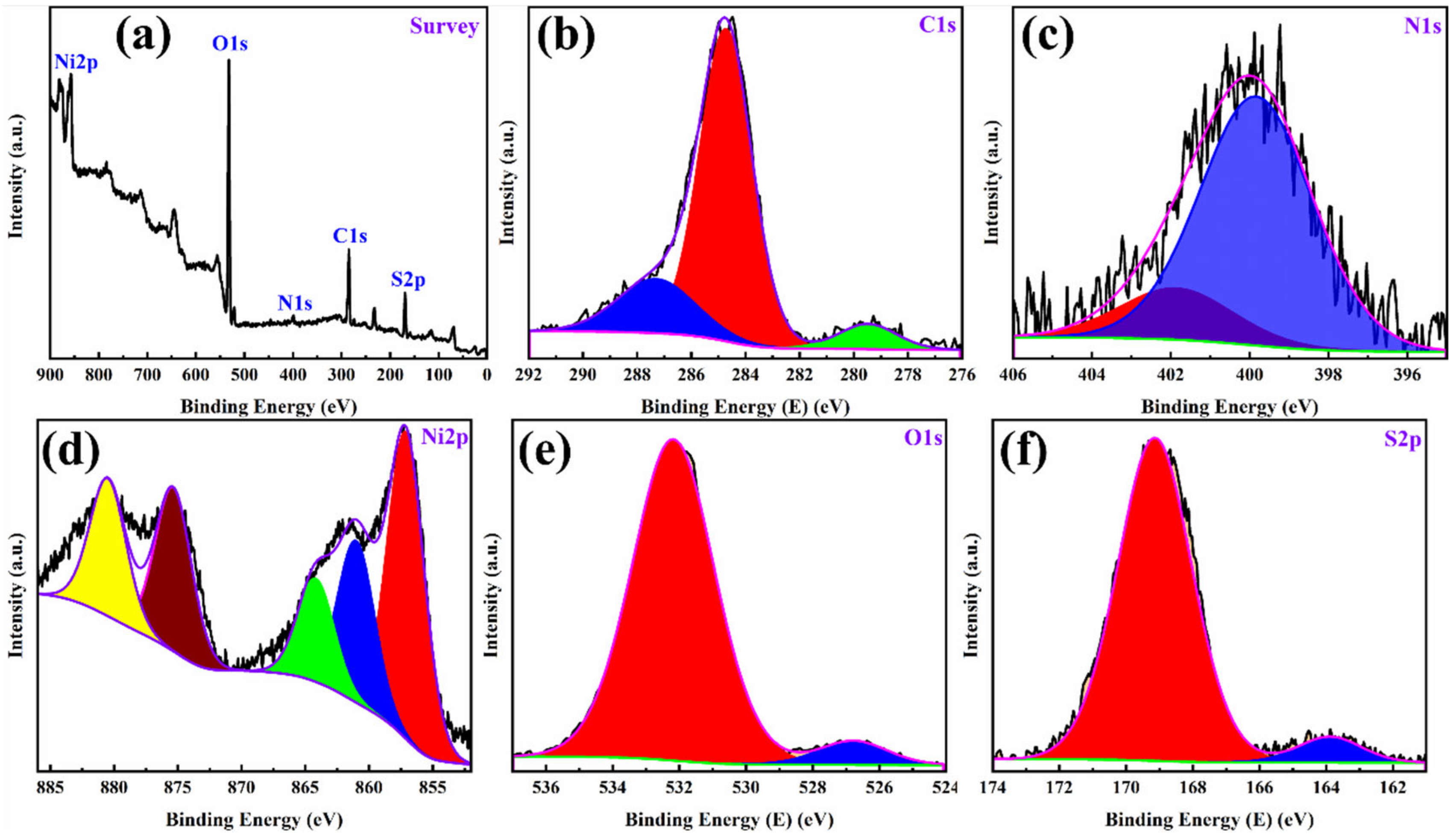
3.1.5. XPS
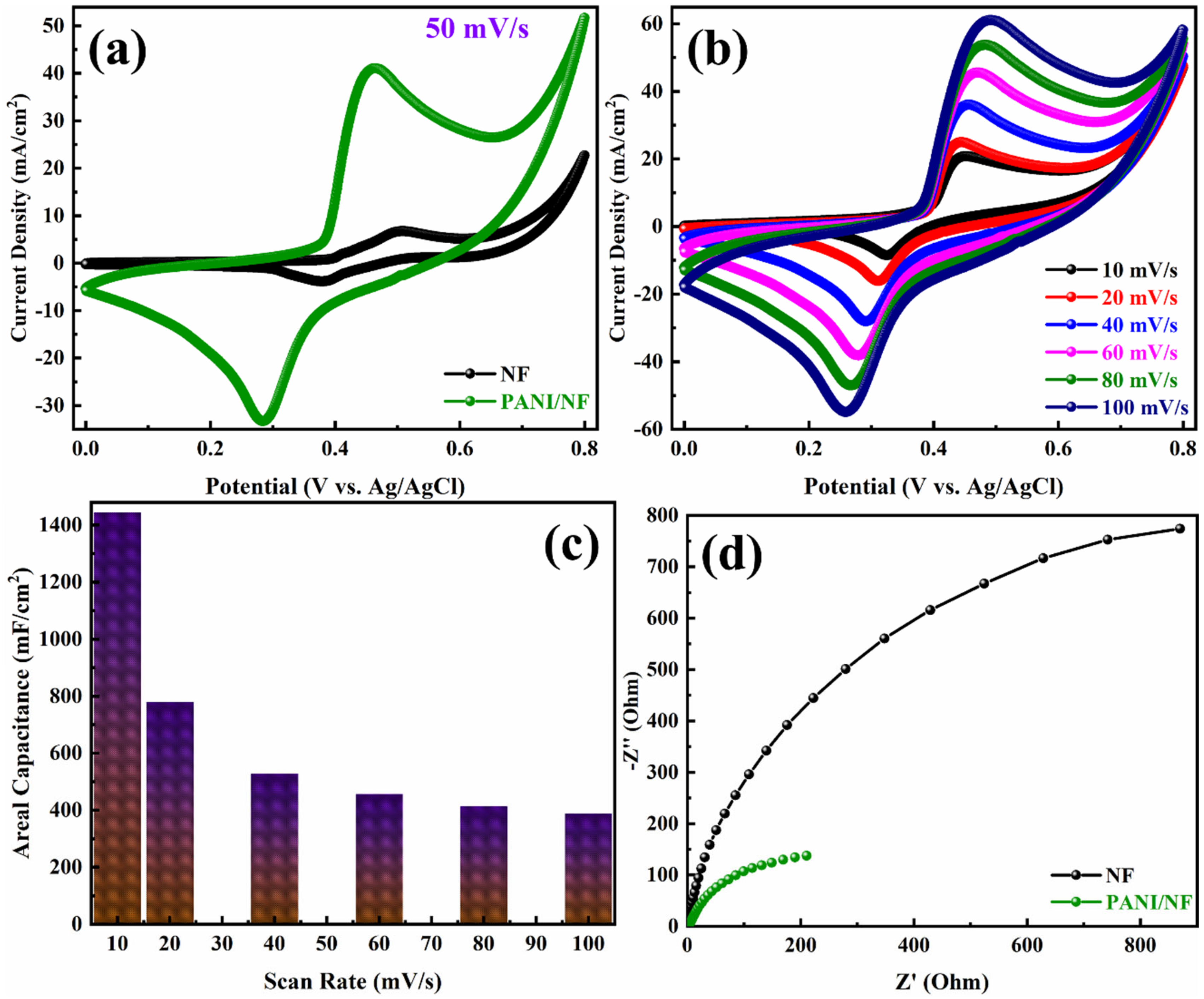
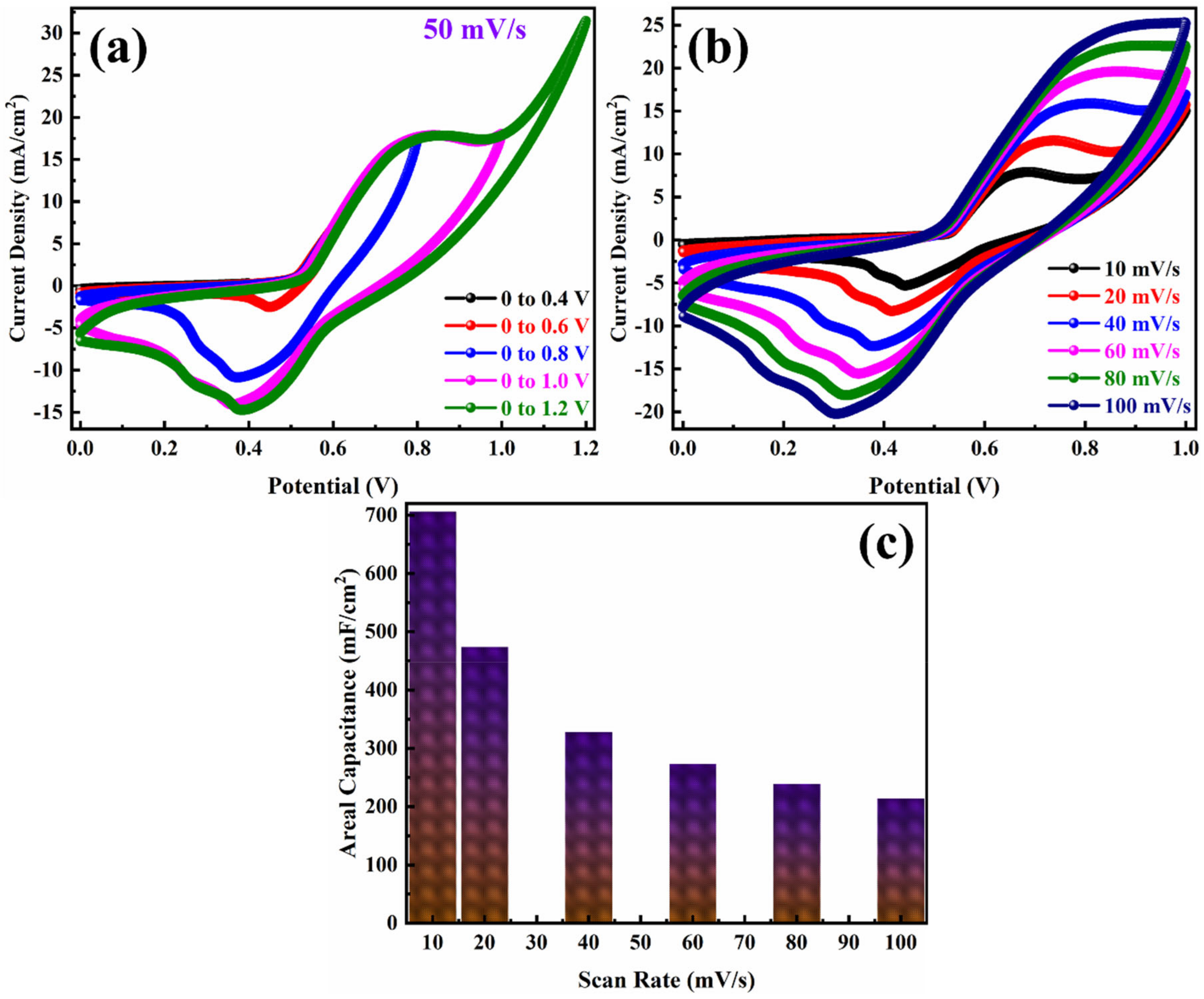
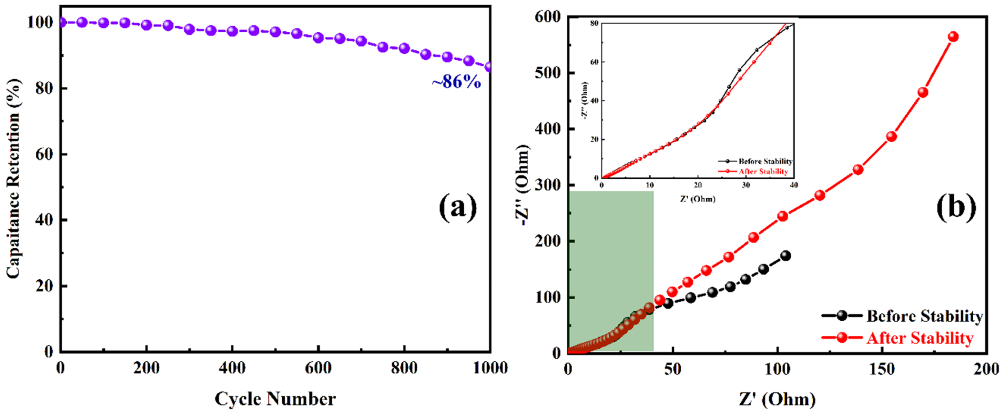
3.2. Electrochemical Analysis of the Electrodeposited PANI/NF and PANI/NF//JAC/NF ASC
4. Conclusions
Author Contributions
Funding
Institutional Review Board Statement
Informed Consent Statement
Acknowledgments
Conflicts of Interest
References
- Dubal, D.P.; Ayyad, O.; Ruiz, V.; Gómez-Romero, P. Hybrid energy storage: The merging of battery and supercapacitor chemistries. Chem. Soc. Rev. 2015, 44, 1777–1790. [Google Scholar] [CrossRef] [PubMed]
- Shah, S.S.; Shaikh, M.N.; Khan, M.Y.; Alfasane, M.A.; Rahman, M.M.; Aziz, M.A. Present Status and Future Prospects of Jute in Nanotechnology: A Review. Chem. Rec. 2021, 21, 1631–1665. [Google Scholar] [CrossRef] [PubMed]
- Shah, S.S.; Nayem, S.M.A.; Sultana, N.; Ahammad, A.J.S.; Aziz, M.A. Preparation of Sulfur-doped Carbon for Supercapacitor Applications: A Review. ChemSusChem 2021, 14, 1–36. [Google Scholar] [CrossRef] [PubMed]
- Simon, P.; Gogotsi, Y.; Dunn, B. Where Do Batteries End and Supercapacitors Begin? Science 2014, 343, 1210–1211. [Google Scholar] [CrossRef] [PubMed] [Green Version]
- Shah, S.S.; Qasem, M.A.A.; Berni, R.; Del Casino, C.; Cai, G.; Contal, S.; Ahmad, I.; Siddiqui, K.S.; Gatti, E.; Predieri, S.; et al. Physico-chemical properties and toxicological effects on plant and algal models of carbon nanosheets from a nettle fibre clone. Sci. Rep. 2021, 11, 6945. [Google Scholar] [CrossRef]
- Balaji, T.E.; Tanaya Das, H.; Maiyalagan, T. Recent Trends in Bimetallic Oxides and Their Composites as Electrode Materials for Supercapacitor Applications. ChemElectroChem 2021, 8, 1723–1746. [Google Scholar] [CrossRef]
- Brousse, T.; Bélanger, D.; Long, J.W. To Be or Not to Be Pseudocapacitive? J. Electrochem. Soc. 2015, 162, A5185–A5189. [Google Scholar] [CrossRef] [Green Version]
- Yaseen, M.; Khattak, M.A.K.; Humayun, M.; Usman, M.; Shah, S.S.; Bibi, S.; Hasnain, B.S.U.; Ahmad, S.M.; Khan, A.; Shah, N.; et al. A Review of Supercapacitors: Materials Design, Modification, and Applications. Energies 2021, 14, 7779. [Google Scholar] [CrossRef]
- Uddin, M.S.; Tanaya Das, H.; Maiyalagan, T.; Elumalai, P. Influence of designed electrode surfaces on double layer capacitance in aqueous electrolyte: Insights from standard models. Appl. Surf. Sci. 2018, 449, 445–453. [Google Scholar] [CrossRef]
- Das, H.T.; Mahendraprabhu, K.; Maiyalagan, T.; Elumalai, P. Performance of Solid-state Hybrid Energy-storage Device using Reduced Graphene-oxide Anchored Sol-gel Derived Ni/NiO Nanocomposite. Sci. Rep. 2017, 7, 15342. [Google Scholar] [CrossRef] [Green Version]
- Das, T.; Verma, B. Synthesis of polymer composite based on polyaniline-acetylene black-copper ferrite for supercapacitor electrodes. Polymer 2019, 168, 61–69. [Google Scholar] [CrossRef]
- Lee, K.S.; Park, C.W.; Phiri, I.; Ko, J.M. New design for Polyaniline@Multiwalled carbon nanotubes composites with bacteria doping for supercapacitor electrodes. Polymer 2020, 210, 123014. [Google Scholar] [CrossRef]
- Wang, H.; Lin, J.; Shen, Z.X. Polyaniline (PANi) based electrode materials for energy storage and conversion. J. Sci. Adv. Mater. Devices 2016, 1, 225–255. [Google Scholar] [CrossRef] [Green Version]
- Shah, S.S.; Alfasane, M.A.; Bakare, I.A.; Aziz, M.A.; Yamani, Z.H. Polyaniline and heteroatoms–enriched carbon derived from Pithophora polymorpha composite for high performance supercapacitor. J. Energy Storage 2020, 30, 101562. [Google Scholar] [CrossRef]
- Xue, M.; Li, F.; Zhu, J.; Song, H.; Zhang, M.; Cao, T. Structure-based enhanced capacitance: In situ growth of highly ordered polyaniline nanorods on reduced graphene oxide patterns. Adv. Funct. Mater. 2012, 22, 1284–1290. [Google Scholar] [CrossRef]
- Banerjee, J.; Dutta, K.; Kader, M.A.; Nayak, S.K. An overview on the recent developments in polyaniline-based supercapacitors. Polym. Adv. Technol. 2019, 30, 1902–1921. [Google Scholar] [CrossRef]
- Zhang, X.; Lin, Z.; Chen, B.; Zhang, W.; Sharma, S.; Gu, W.; Deng, Y. Solid-state flexible polyaniline/silver cellulose nanofibrils aerogel supercapacitors. J. Power Sources 2014, 246, 283–289. [Google Scholar] [CrossRef]
- Yu, M.; Ma, Y.; Liu, J.; Li, S. Polyaniline nanocone arrays synthesized on three-dimensional graphene network by electrodeposition for supercapacitor electrodes. Carbon 2015, 87, 98–105. [Google Scholar] [CrossRef]
- Yavuz, A.; Yilmaz Erdogan, P.; Zengin, H. The use of polyaniline films on flexible tape for supercapacitor applications. Int. J. Energy Res. 2020, 44, 11941–11955. [Google Scholar] [CrossRef]
- Aydinli, A.; Yuksel, R.; Unalan, H.E. Vertically aligned carbon nanotube—Polyaniline nanocomposite supercapacitor electrodes. Int. J. Hydrogen Energy 2018, 43, 18617–18625. [Google Scholar] [CrossRef]
- Shaikh, S.F.; Shaikh, F.F.M.; Shaikh, A.V.; Ubaidullah, M.; Al-Enizi, A.M.; Pathan, H.M. Electrodeposited more-hydrophilic nano-nest polyaniline electrodes for supercapacitor application. J. Phys. Chem. Solids 2021, 149, 109774. [Google Scholar] [CrossRef]
- Zhong, M.; Song, Y.; Li, Y.; Ma, C.; Zhai, X.; Shi, J.; Guo, Q.; Liu, L. Effect of reduced graphene oxide on the properties of an activated carbon cloth/polyaniline flexible electrode for supercapacitor application. J. Power Sources 2012, 217, 6–12. [Google Scholar] [CrossRef]
- Xie, Y.; Liu, Y.; Zhao, Y.; Tsang, Y.H.; Lau, S.P.; Huang, H.; Chai, Y. Stretchable all-solid-state supercapacitor with wavy shaped polyaniline/graphene electrode. J. Mater. Chem. A 2014, 2, 9142–9149. [Google Scholar] [CrossRef]
- Ruan, C.; Li, P.; Xu, J.; Xie, Y. Electrochemical performance of hybrid membrane of polyaniline layer/full carbon layer coating on nickel foam. Prog. Org. Coat. 2020, 139, 105455. [Google Scholar] [CrossRef]
- Shah, S.S.; Cevik, E.; Aziz, M.A.; Qahtan, T.F.; Bozkurt, A.; Yamani, Z.H. Jute Sticks Derived and Commercially Available Activated Carbons for Symmetric Supercapacitors with Bio-electrolyte: A Comparative Study. Synth. Met. 2021, 277, 116765. [Google Scholar] [CrossRef]
- Lu, H.; Zhao, X.S. Biomass-derived carbon electrode materials for supercapacitors. Sustain. Energy Fuels 2017, 1, 1265–1281. [Google Scholar] [CrossRef]
- Qian, W.; Sun, F.; Xu, Y.; Qiu, L.; Liu, C.; Wang, S.; Yan, F. Human hair-derived carbon flakes for electrochemical supercapacitors. Energy Environ. Sci. 2013, 7, 379–386. [Google Scholar] [CrossRef]
- Yuan, C.; Lin, H.; Lu, H.; Xing, E.; Zhang, Y.; Xie, B. Synthesis of hierarchically porous MnO2/rice husks derived carbon composite as high-performance electrode material for supercapacitors. Appl. Energy 2016, 178, 260–268. [Google Scholar] [CrossRef]
- Zhan, C.; Yu, X.; Liang, Q.; Liu, W.; Wang, Y.; Lv, R.; Huang, Z.H.; Kang, F. Flour food waste derived activated carbon for high-performance supercapacitors. RSC Adv. 2016, 6, 89391–89396. [Google Scholar] [CrossRef]
- Song, M.; Zhou, Y.; Ren, X.; Wan, J.; Du, Y.; Wu, G.; Ma, F. Biowaste-based porous carbon for supercapacitor: The influence of preparation processes on structure and performance. J. Colloid Interface Sci. 2019, 535, 276–286. [Google Scholar] [CrossRef]
- Islam, T.; Hasan, M.M.; Shah, S.S.; Karim, M.R.; Al-Mubaddel, F.S.; Zahir, M.H.; Dar, M.A.; Hossain, M.D.; Aziz, M.A.; Ahammad, A.J.S. High yield activated porous coal carbon nanosheets from Boropukuria coal mine as supercapacitor material: Investigation of the charge storing mechanism at the interfacial region. J. Energy Storage 2020, 32, 101908. [Google Scholar] [CrossRef]
- Mohamedkhair, A.K.; Aziz, M.A.; Shah, S.S.; Shaikh, M.N.; Jamil, A.K.; Qasem, M.A.A.; Buliyaminu, I.A.; Yamani, Z.H. Effect of an activating agent on the physicochemical properties and supercapacitor performance of naturally nitrogen-enriched carbon derived from Albizia procera leaves. Arab. J. Chem. 2020, 13, 6161–6173. [Google Scholar] [CrossRef]
- Deb Nath, N.C.; Shah, S.S.; Qasem, M.A.A.; Zahir, M.H.; Aziz, M.A. Defective Carbon Nanosheets Derived from Syzygium cumini Leaves for Electrochemical Energy-Storage. ChemistrySelect 2019, 4, 9079–9083. [Google Scholar] [CrossRef]
- Chen, X.; Wang, X.; Li, L.; Qi, S. Preparation and microwave absorbing properties of nickel-coated carbon fiber with polyaniline via in situ polymerization. J. Mater. Sci. Mater. Electron. 2016, 27, 5607–5612. [Google Scholar] [CrossRef]
- Padmapriya, S.; Harinipriya, S.; Jaidev, K.; Sudha, V.; Kumar, D.; Pal, S. Storage and evolution of hydrogen in acidic medium by polyaniline. Int. J. Energy Res. 2018, 42, 1196–1209. [Google Scholar] [CrossRef]
- Cai, X.; Cui, X.; Zu, L.; Zhang, Y.; Gao, X.; Lian, H.; Liu, Y.; Wang, X. Ultra High Electrical Performance of Nano Nickel Oxide and Polyaniline Composite Materials. Polymers 2017, 9, 288. [Google Scholar] [CrossRef] [Green Version]
- Peng, H.; Ma, G.; Sun, K.; Mu, J.; Zhou, X.; Lei, Z. A novel fabrication of nitrogen-containing carbon nanospheres with high rate capability as electrode materials for supercapacitors. RSC Adv. 2015, 5, 12034–12042. [Google Scholar] [CrossRef]
- Fahim, M.; Shah, A.U.H.A.; Bilal, S. Highly Stable and Efficient Performance of Binder-Free Symmetric Supercapacitor Fabricated with Electroactive Polymer Synthesized via Interfacial Polymerization. Materials 2019, 12, 1626. [Google Scholar] [CrossRef] [Green Version]
- Gul, H.; Shah, A.-U.-H.A.; Krewer, U.; Bilal, S. Study on Direct Synthesis of Energy Efficient Multifunctional Polyaniline–Graphene Oxide Nanocomposite and Its Application in Aqueous Symmetric Supercapacitor Devices. Nanomaterials 2020, 10, 118. [Google Scholar] [CrossRef] [Green Version]
- Zia, T.U.H.; Ali Shah, A.U.H. Understanding the adsorption of 1 NLB antibody on polyaniline nanotubes as a function of zeta potential and surface charge density for detection of hepatitis C core antigen: A label-free impedimetric immunosensor. Colloids Surf. A Physicochem. Eng. Asp. 2021, 626, 127076. [Google Scholar] [CrossRef]
- Farooq, S.; Tahir, A.A.; Krewer, U.; Shah, A.U.H.A.; Bilal, S. Efficient photocatalysis through conductive polymer coated FTO counter electrode in platinum free dye sensitized solar cells. Electrochim. Acta 2019, 320, 134544. [Google Scholar] [CrossRef]
- Duraisamy, E.; Das, H.T.; Selva Sharma, A.; Elumalai, P. Supercapacitor and photocatalytic performances of hydrothermally-derived Co3O4/CoO@carbon nanocomposite. New J. Chem. 2018, 42, 6114–6124. [Google Scholar] [CrossRef]
- Rajkumar, S.; Elanthamilan, E.; Balaji, T.E.; Sathiyan, A.; Jafneel, N.E.; Merlin, J.P. Recovery of copper oxide nanoparticles from waste SIM cards for supercapacitor electrode material. J. Alloys Compd. 2020, 849, 156582. [Google Scholar] [CrossRef]
- Sun, H.; She, P.; Xu, K.; Shang, Y.; Yin, S.; Liu, Z. A self-standing nanocomposite foam of polyaniline@reduced graphene oxide for flexible super-capacitors. Synth. Met. 2015, 209, 68–73. [Google Scholar] [CrossRef]
- Liu, W.; Yan, X.; Chen, J.; Feng, Y.; Xue, Q. Novel and high-performance asymmetric micro-supercapacitors based on graphene quantum dots and polyaniline nanofibers. Nanoscale 2013, 5, 6053–6062. [Google Scholar] [CrossRef]
- Zeng, S.; Chen, H.; Cai, F.; Kang, Y.; Chen, M.; Li, Q. Electrochemical fabrication of carbon nanotube/polyaniline hydrogel film for all-solid-state flexible supercapacitor with high areal capacitance. J. Mater. Chem. A 2015, 3, 23864–23870. [Google Scholar] [CrossRef]
- Wu, W.; Wang, X.; Deng, Y.; Zhou, C.; Wang, Z.; Zhang, M.; Li, X.; Wu, Y.; Luo, Y.; Chen, D. In situ synthesis of polyaniline/carbon nanotube composites in a carbonized wood scaffold for high performance supercapacitors. Nanoscale 2020, 12, 17738–17745. [Google Scholar] [CrossRef]
- Horng, Y.Y.; Lu, Y.C.; Hsu, Y.K.; Chen, C.C.; Chen, L.C.; Chen, K.H. Flexible supercapacitor based on polyaniline nanowires/carbon cloth with both high gravimetric and area-normalized capacitance. J. Power Sources 2010, 195, 4418–4422. [Google Scholar] [CrossRef]
- Ryu, K.S.; Kim, K.M.; Park, N.G.; Park, Y.J.; Chang, S.H. Symmetric redox supercapacitor with conducting polyaniline electrodes. J. Power Sources 2002, 103, 305–309. [Google Scholar] [CrossRef]
- Huang, Z.; Ji, Z.; Feng, Y.; Wang, P.; Huang, Y. Flexible and stretchable polyaniline supercapacitor with a high rate capability. Polym. Int. 2021, 70, 437–442. [Google Scholar] [CrossRef]
- Simotwo, S.K.; Delre, C.; Kalra, V. Supercapacitor Electrodes Based on High-Purity Electrospun Polyaniline and Polyaniline-Carbon Nanotube Nanofibers. ACS Appl. Mater. Interfaces 2016, 8, 21261–21269. [Google Scholar] [CrossRef]
- Cho, S.; Shin, K.H.; Jang, J. Enhanced electrochemical performance of highly porous supercapacitor electrodes based on solution processed polyaniline thin films. ACS Appl. Mater. Interfaces 2013, 5, 9186–9193. [Google Scholar] [CrossRef] [PubMed]
- Gopalakrishnan, A.; Badhulika, S. Binder-free polyaniline sheathed crumpled cobalt diselenide nanoparticles as an advanced electrode for high specific energy asymmetric supercapacitor. J. Energy Storage 2021, 41, 102853. [Google Scholar] [CrossRef]
- Gao, S.; Zhang, L.; Qiao, Y.; Dong, P.; Shi, J.; Cao, S. Electrodeposition of polyaniline on three-dimensional graphene hydrogel as a binder-free supercapacitor electrode with high power and energy densities. RSC Adv. 2016, 6, 58854–58861. [Google Scholar] [CrossRef]
- Liu, Z.; Zhao, Z.; Xu, A.; Li, W.; Qin, Y. Facile preparation of graphene/polyaniline composite hydrogel film by electrodeposition for binder-free all-solid-state supercapacitor. J. Alloys Compd. 2021, 875, 159931. [Google Scholar] [CrossRef]
- Malik, R.; Zhang, L.; McConnell, C.; Schott, M.; Hsieh, Y.Y.; Noga, R.; Alvarez, N.T.; Shanov, V. Three-dimensional, free-standing polyaniline/carbon nanotube composite-based electrode for high-performance supercapacitors. Carbon 2017, 116, 579–590. [Google Scholar] [CrossRef]
- Hou, L.; Zhi, X.; Zhang, W.; Zhou, H. Boosting the electrochemical properties of polyaniline by one-step co-doped electrodeposition for high performance flexible supercapacitor applications. J. Electroanal. Chem. 2020, 863, 114064. [Google Scholar] [CrossRef]


| From CV Curves | From GCD Profiles | ||||
|---|---|---|---|---|---|
| Scan Rate (mV/s) | Areal Capacitance (mF/cm2) | Current Density (mA/cm2) | Areal Capacitance (mF/cm2) | Energy Density (µWh/cm2) | Power Density (µW/cm2) |
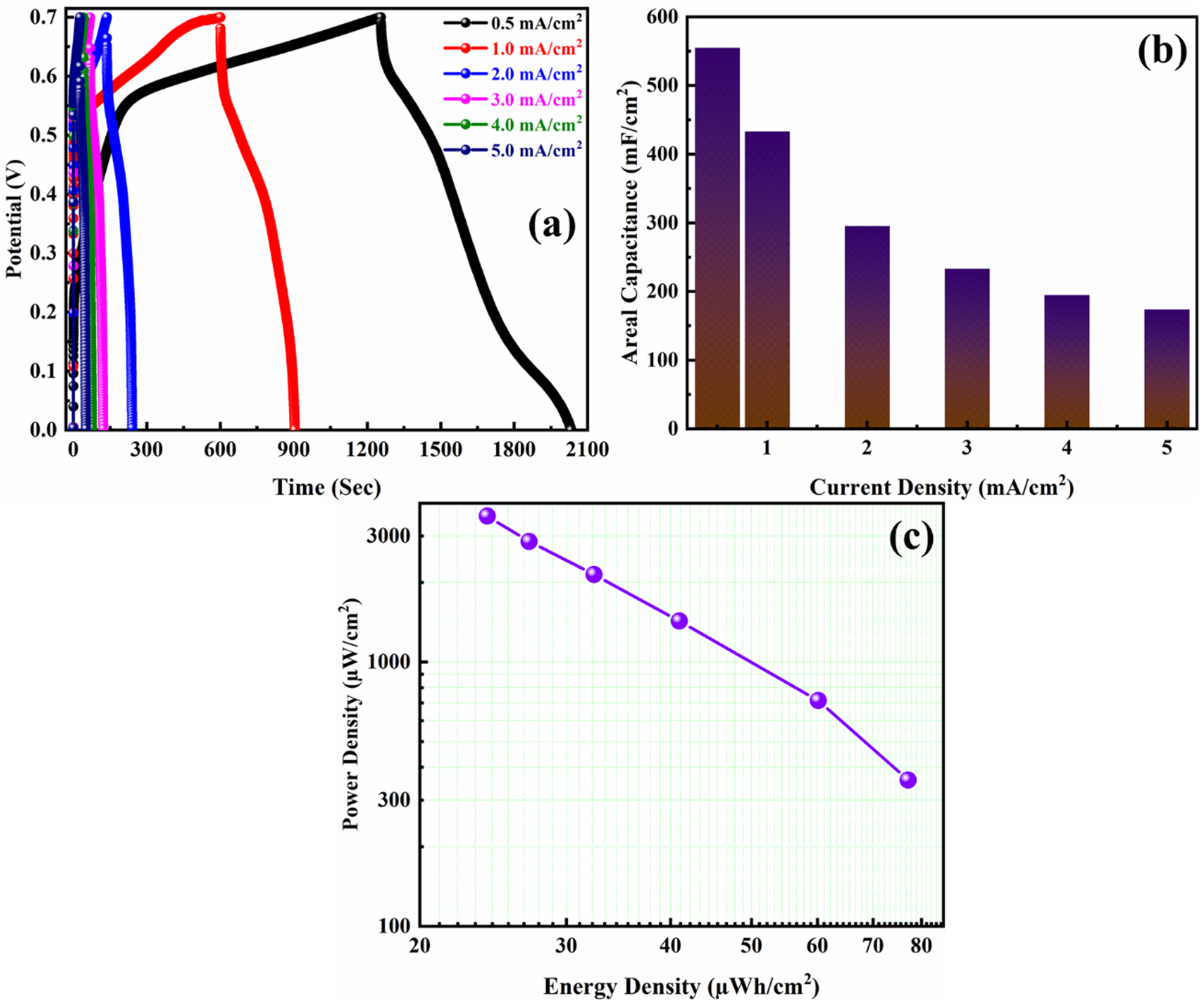
| 10 | 706 | 0.5 | 555 | 77 | 357 |
| 20 | 474 | 1.0 | 433 | 60 | 714 |
| 40 | 328 | 2.0 | 295 | 41 | 1429 |
| 60 | 273 | 3.0 | 233 | 32 | 2143 |
| 80 | 238 | 4.0 | 195 | 27 | 2857 |
| 100 | 214 | 5.0 | 174 | 24 | 3571 |
| Positive Electrode | Negative Electrode | Electrolyte | Capacitance (F/g or F/cm2) | Current Density or Scan Rate | Energy Density | Power Density | Capacitance Retention (%) @ Cycles | Ref. |
|---|---|---|---|---|---|---|---|---|
| GQDs | PANI | H3PO4–PVA | 210 μF/cm2 | 15.0 μA/cm2 | 0.029 μWh/cm2 | 7.46 μW/cm2 | 85.6 % @ 1500 | [45] |
| PANI/graphene | PANI/graphene | H3PO4/PVA | 261.24 F/g | 0.38 A/g | 23.2Wh/kg | 399 W/kg | 89% @ 1000 | [23] |
| CNT/PANI | CNT/PANI | PVA–H2SO4 | 680 mF/cm2 | 1 mA/cm2 | … | … | 100% @ 500 | [46] |
| PANI@CNT/AWC | PANI@CNT/AWC | H3PO4-PVA | 1019.5 F/g | 10 mA/cm2 | 40.5 Wh/kg | 162.5 W/kg | 93.74% @ 10000 | [47] |
| PANI/cellulose/PANI | PANI/cellulose/PANI | 1M H2SO4 | 1079 F/g | 1.73 A/g | 100.9Wh/kg | 12.1 kW/kg | 86% @ 2100 | [48] |
| PANI-LiPF6 | PANI-LiPF6 | Et4NbF4 | 107 F/g | 1.25 mA/cm2 | … | … | 78.5% @ 9000 | [49] |
| PANI | PANI | H3PO4-PVA | 282 F/g | 2.5 A/g | … | … | 55% @ 200 | [50] |
| PANI/CNT/PEO | PANI/CNT/PEO | 1M H2SO4 | 385 F/g | 0.5 A/g | 7.11 Wh/kg | 201 W/kg | 81.4% @ 1000 | [51] |
| BPO–PANI | BPO-PANI | 0.5 M H2SO4 | 361 F/g | 0.25 A/g | … | … | 72.2 @ 500 | [52] |
| PANI/CoSe2/NF | AC/NF | 6 M KOH | 434 F/g | 0.25 A/g | 118 Wh/kg | 462 W/kg | 82% @ 10000 | [53] |
| GH/PANI | GH/PANI | 1 M H2SO4 | 710 F/g | 2 A/g | 24 Wh/kg | 30 kW/kg | 86% @ 1000 | [54] |
| rGO/PANI | rGO/PANI | 1 M H2SO4 | 853.7 F/g | 1 A/g | 14.8 Wh/kg | 6.7 kW/kg | 92.6% @ 8000 | [55] |
| PANI/NCNT | PANI/NCNT | PVA/H2SO4 | 128 F/g | 2.47 A/g | 11.1 Wh/kg | 0.98 kW/kg | 92% @ 10000 | [56] |
| SP–PANI | SP-PANI | PVA/H2SO4 | 149.3 F/g | 0.5 mA/cm2 | 13.0 μWh/cm2 | 0.40 mW/cm2 | 81.2% @ 5000 | [57] |
| PANI/Ag/CNF | PANI/Ag/CNF | H3PO4-PVA | 176 mF/cm2 | 10 mV/s | 10.6 Wh/kg | 225 kW/kg | … | [17] |
| PANI/NF | JAC/NF | 3 M KOH | 555 mF/cm2 | 0.5 mA/cm2 | 777 µWh/cm2 | 357 µW/cm2 | 86 @ 1000 | This Work |
Publisher’s Note: MDPI stays neutral with regard to jurisdictional claims in published maps and institutional affiliations. |
© 2022 by the authors. Licensee MDPI, Basel, Switzerland. This article is an open access article distributed under the terms and conditions of the Creative Commons Attribution (CC BY) license (https://creativecommons.org/licenses/by/4.0/).
Share and Cite
Shah, S.S.; Das, H.T.; Barai, H.R.; Aziz, M.A. Boosting the Electrochemical Performance of Polyaniline by One-Step Electrochemical Deposition on Nickel Foam for High-Performance Asymmetric Supercapacitor. Polymers 2022, 14, 270. https://doi.org/10.3390/polym14020270
Shah SS, Das HT, Barai HR, Aziz MA. Boosting the Electrochemical Performance of Polyaniline by One-Step Electrochemical Deposition on Nickel Foam for High-Performance Asymmetric Supercapacitor. Polymers. 2022; 14(2):270. https://doi.org/10.3390/polym14020270
Chicago/Turabian StyleShah, Syed Shaheen, Himadri Tanaya Das, Hasi Rani Barai, and Md. Abdul Aziz. 2022. "Boosting the Electrochemical Performance of Polyaniline by One-Step Electrochemical Deposition on Nickel Foam for High-Performance Asymmetric Supercapacitor" Polymers 14, no. 2: 270. https://doi.org/10.3390/polym14020270
APA StyleShah, S. S., Das, H. T., Barai, H. R., & Aziz, M. A. (2022). Boosting the Electrochemical Performance of Polyaniline by One-Step Electrochemical Deposition on Nickel Foam for High-Performance Asymmetric Supercapacitor. Polymers, 14(2), 270. https://doi.org/10.3390/polym14020270