
Effects of the Pre-Consolidated Materials Manufacturing Method on the Mechanical Properties of Pultruded Thermoplastic Composites

 ,
,  , ,
, ,  and
and 
Abstract
:
1. Introduction
2. Materials and Methods
2.1. Manufacturing of PCTs
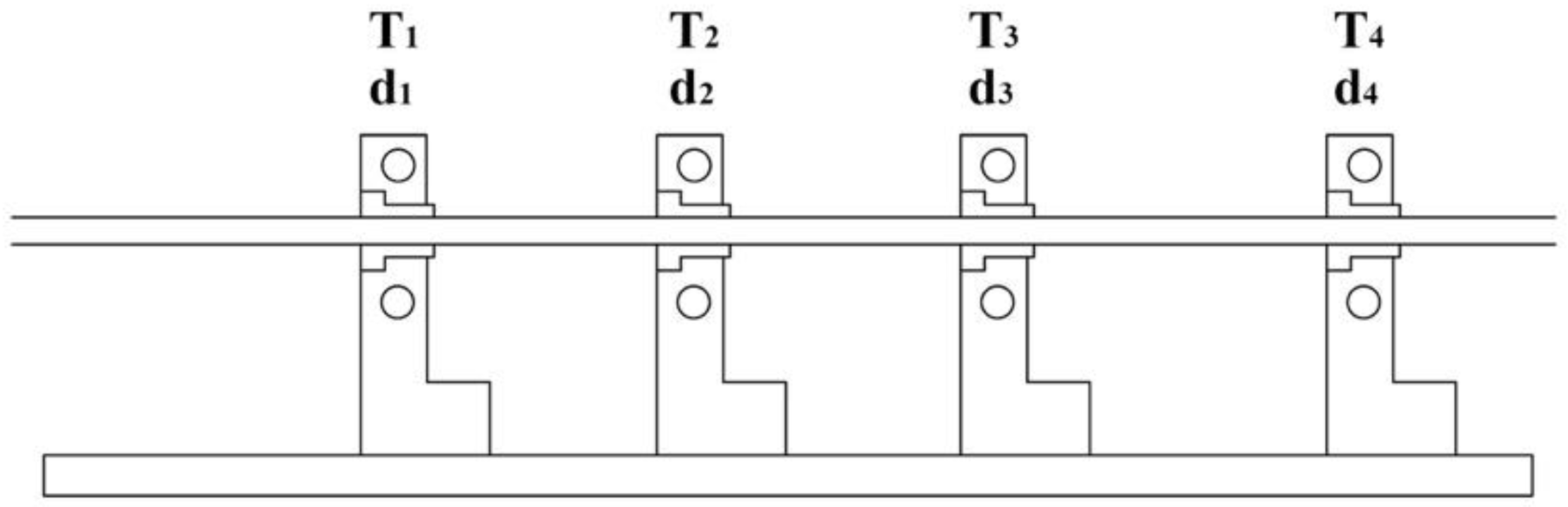
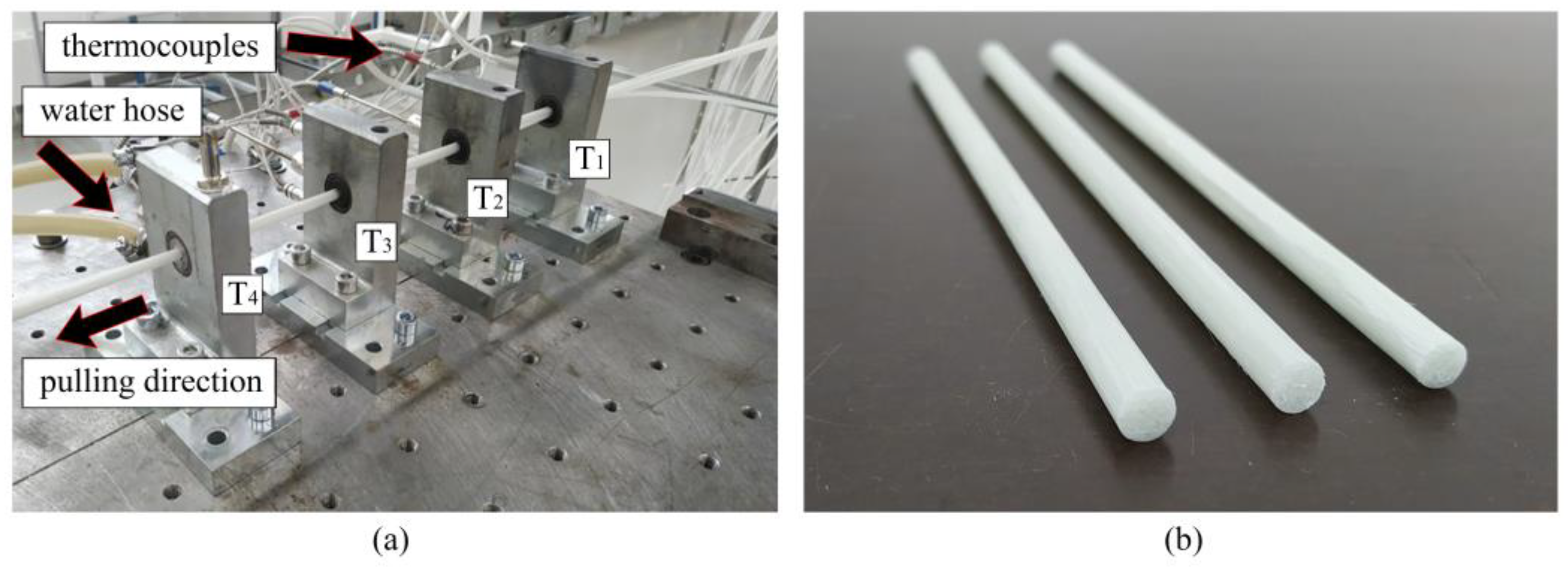
2.2. Pultrusion Setup
2.2.1. Manufacturing of Thermoplastic Bars
2.2.2. Manufacturing of Thermoplastic Flat Laminates
2.3. Morphology Analysis Using an Optical Microscope
2.4. Thermal Analysis
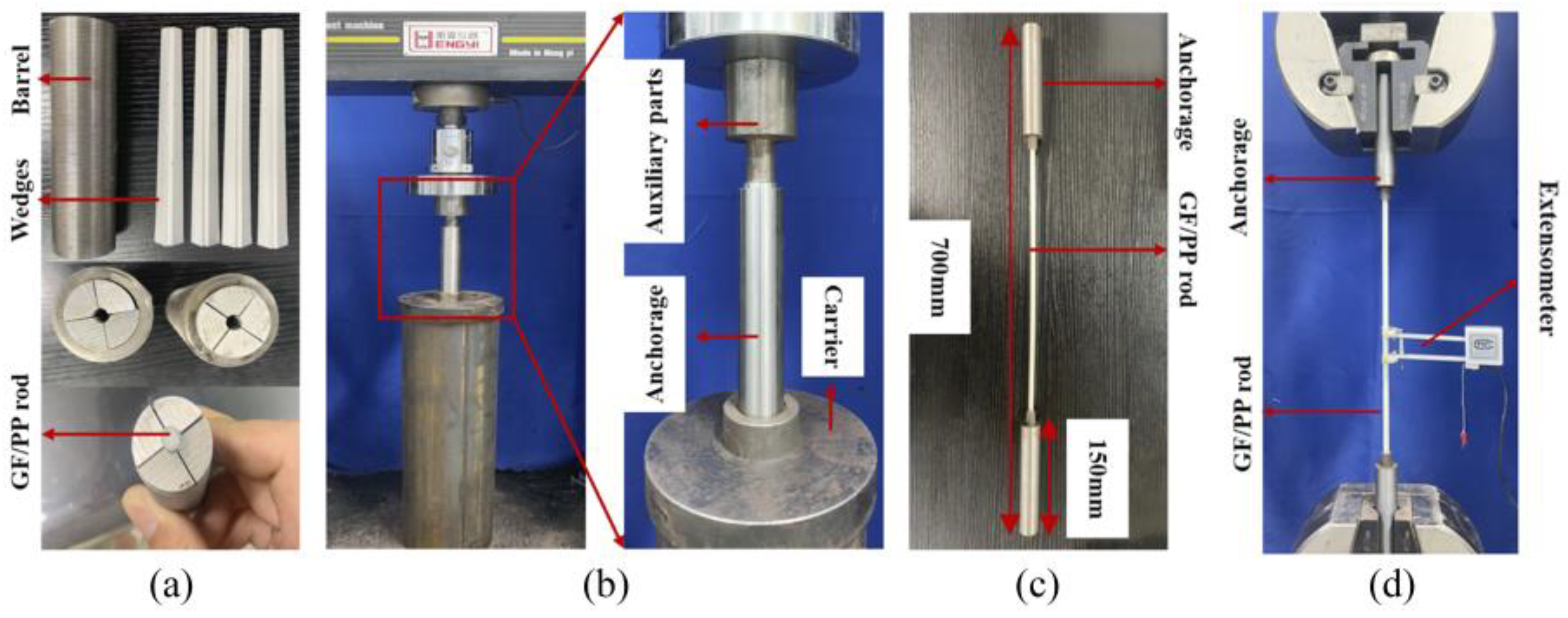
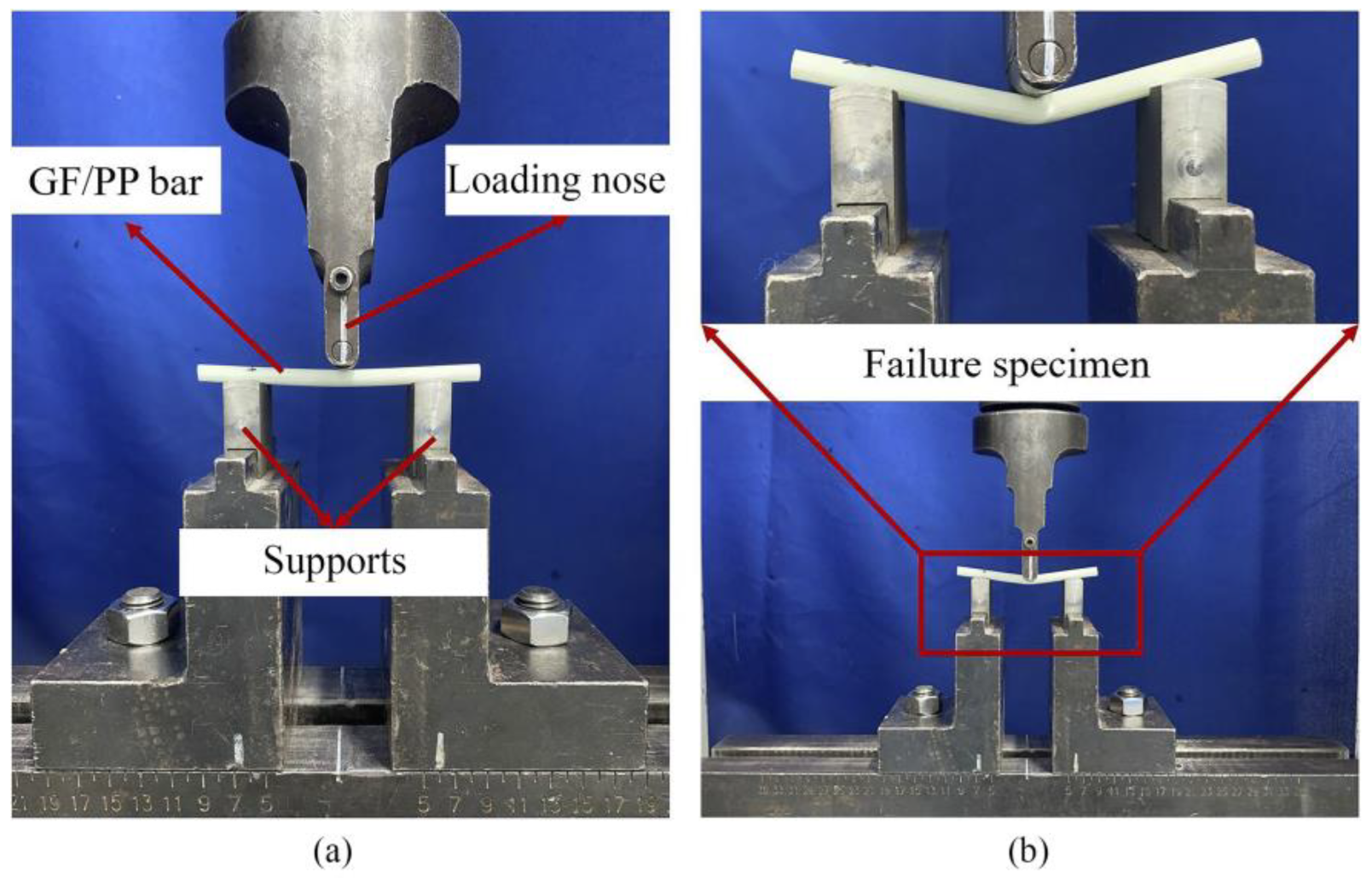
2.5. Mechanical Tests
3. Results and Discussions
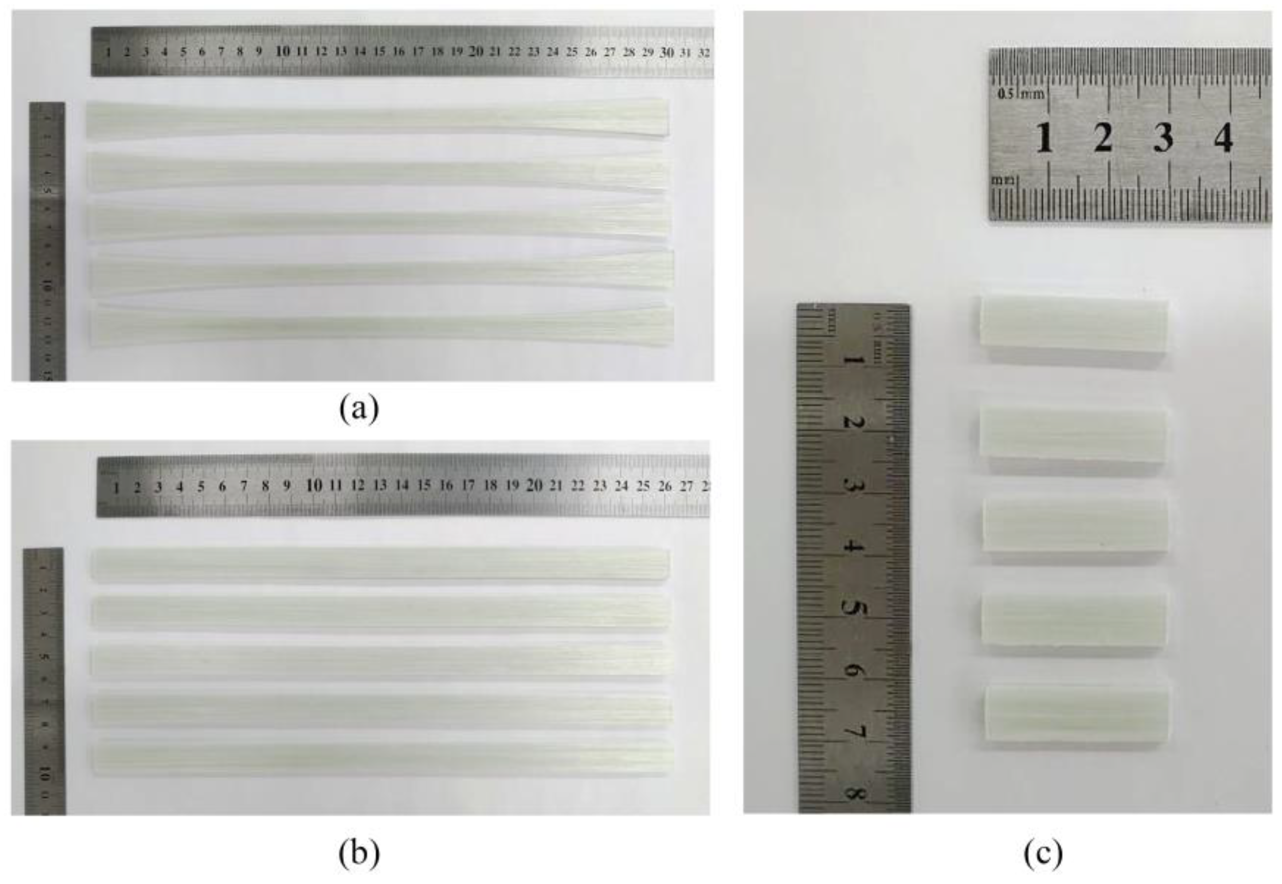
3.1. Fabrication of Inhouse-Made PCTs, Pultruded Thermoplastic Bars, and Flat Laminates
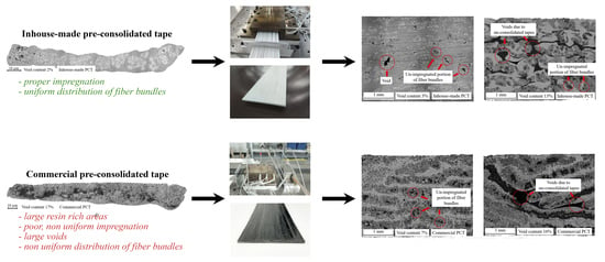
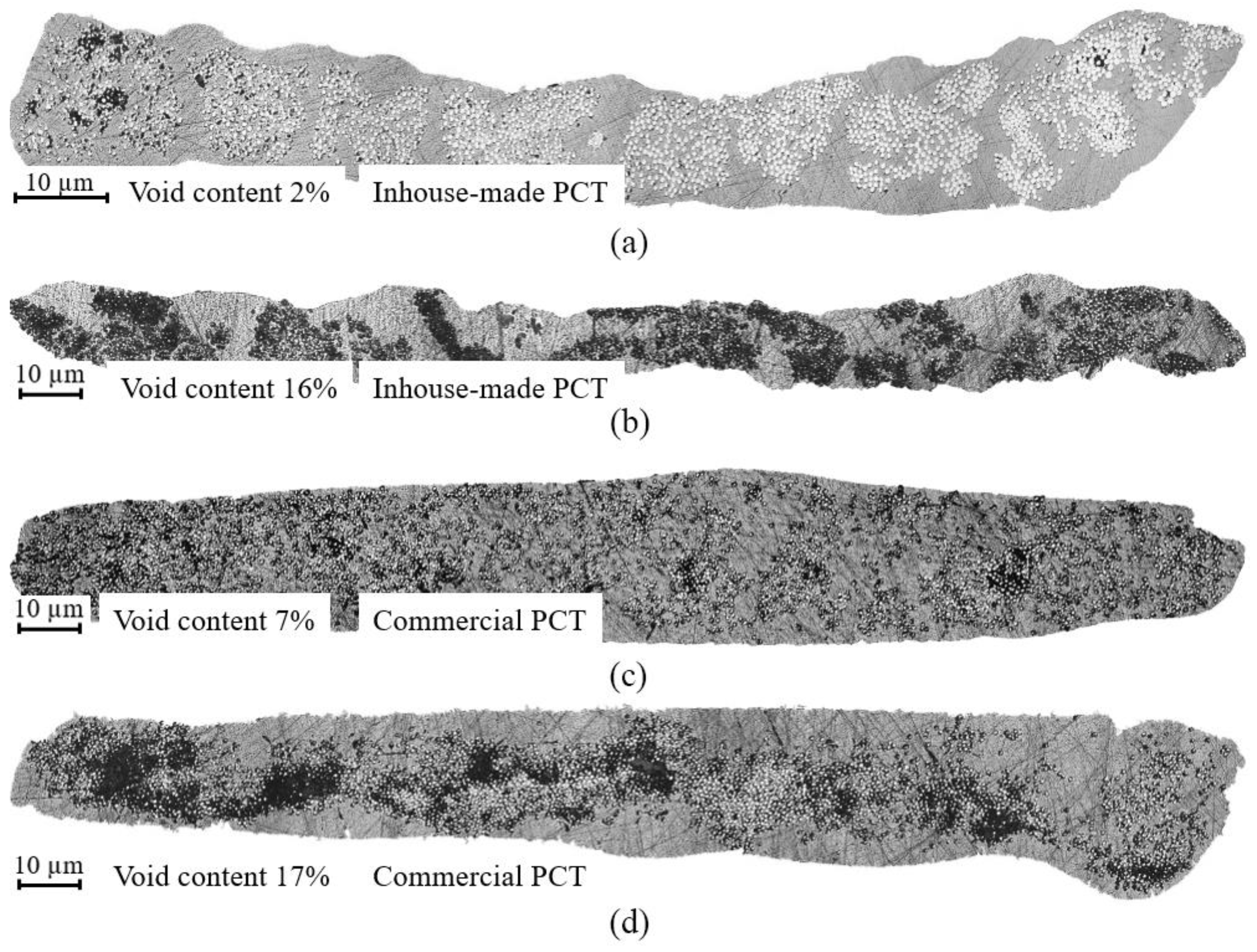
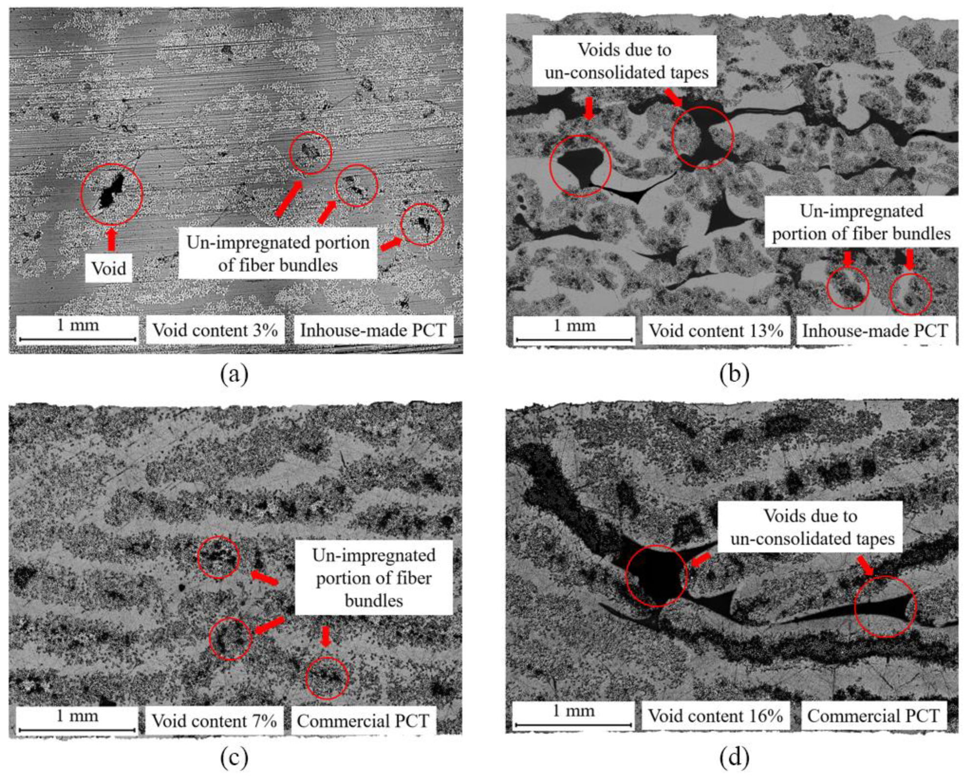
3.2. Results of Morphology Analysis
3.3. Results of Thermal Analysis
3.4. Mechanical Testing Results
4. Conclusions
Author Contributions
Funding
Data Availability Statement
Acknowledgments
Conflicts of Interest
References
- Vedernikov, A.; Safonov, A.; Tucci, F.; Carlone, P.; Akhatov, I. Pultruded Materials and Structures: A Review. J. Compos. Mater. 2020, 54, 4081–4117. [Google Scholar] [CrossRef]
- Duc, F.; Bourban, P.E.; Plummer, C.J.G.; Månson, J.-A.E. Damping of Thermoset and Thermoplastic Flax Fibre Composites. Compos. Part A Appl. Sci. Manuf. 2014, 64, 115–123. [Google Scholar] [CrossRef]
- Han, N.; Baran, I.; Zanjani, J.S.M.; Yuksel, O.; An, L.; Akkerman, R. Experimental and Computational Analysis of the Polymerization Overheating in Thick Glass/Elium® Acrylic Thermoplastic Resin Composites. Compos. Part B Eng. 2020, 202, 108430. [Google Scholar] [CrossRef]
- Asensio, M.; Esfandiari, P.; Núñez, K.; Silva, J.F.; Marques, A.; Merino, J.C.; Pastor, J.M. Processing of Pre-Impregnated Thermoplastic Towpreg Reinforced by Continuous Glass Fibre and Recycled PET by Pultrusion. Compos. Part B Eng. 2020, 200, 108365. [Google Scholar] [CrossRef]
- Lebel, L.L.; Nakai, A. Design and Manufacturing of an L-Shaped Thermoplastic Composite Beam by Braid-Trusion. Compos. Part A Appl. Sci. Manuf. 2012, 43, 1717–1729. [Google Scholar] [CrossRef]
- Volk, M.; Wong, J.; Arreguin, S.; Ermanni, P. Pultrusion of Large Thermoplastic Composite Profiles up to Ø 40 Mm from Glass-Fibre/PET Commingled Yarns. Compos. Part B Eng. 2021, 227, 109339. [Google Scholar] [CrossRef]
- Stavrov, D.; Bersee, H.E.N. Resistance Welding of Thermoplastic Composites—An Overview. Compos. Part A Appl. Sci. Manuf. 2005, 36, 39–54. [Google Scholar] [CrossRef]
- Holmes, J.; Vlandis, G.; Stachurski, Z.; Das, R.; Compston, P. Failure Behaviour in Woven Thermoplastic Composites Subjected to Various Deformation Modes. Compos. Part A Appl. Sci. Manuf. 2021, 146, 106410. [Google Scholar] [CrossRef]
- Minchenkov, K.; Vedernikov, A.; Safonov, A.; Akhatov, I. Thermoplastic Pultrusion: A Review. Polymers 2021, 13, 180. [Google Scholar] [CrossRef]
- Ferdous, W.; Manalo, A.; AlAjarmeh, O.; Mohammed, A.A.; Salih, C.; Yu, P.; Mehrinejad Khotbehsara, M.; Schubel, P. Static Behaviour of Glass Fibre Reinforced Novel Composite Sleepers for Mainline Railway Track. Eng. Struct. 2021, 229, 111627. [Google Scholar] [CrossRef]
- Fortier, V.; Brunel, J.-E.; Lebel, L. Fastening Composite Structures Using Braided Thermoplastic Composite Rivets. J. Compos. Mater. 2019, 54, 002199831986737. [Google Scholar] [CrossRef]
- Korotkov, R.; Vedernikov, A.; Gusev, S.; Alajarmeh, O.; Akhatov, I.; Safonov, A. Shape Memory Behavior of Unidirectional Pultruded Laminate. Compos. Part A Appl. Sci. Manuf. 2021, 150, 106609. [Google Scholar] [CrossRef]
- Rubino, F.; Nisticò, A.; Tucci, F.; Carlone, P. Marine Application of Fiber Reinforced Composites: A Review. J. Mar. Sci. Eng. 2020, 8, 26. [Google Scholar] [CrossRef] [Green Version]
- Alajarmeh, O.; Zeng, X.; Aravinthan, T.; Shelley, T.; Alhawamdeh, M.; Mohammed, A.; Nicol, L.; Vedernikov, A.; Safonov, A.; Schubel, P. Compressive Behaviour of Hollow Box Pultruded FRP Columns with Continuous-Wound Fibres. Thin-Walled Struct. 2021, 168, 108300. [Google Scholar] [CrossRef]
- Gemi, L.; Madenci, E.; Özkılıç, Y.O. Experimental, Analytical and Numerical Investigation of Pultruded GFRP Composite Beams Infilled with Hybrid FRP Reinforced Concrete. Eng. Struct. 2021, 244, 112790. [Google Scholar] [CrossRef]
- Madenci, E.; Onuralp Özkılıç, Y.; Gemi, L. Buckling and Free Vibration Analyses of Pultruded GFRP Laminated Composites: Experimental, Numerical and Analytical Investigations. Compos. Struct. 2020, 254, 112806. [Google Scholar] [CrossRef]
- Alhawamdeh, M.; Alajarmeh, O.; Aravinthan, T.; Shelley, T.; Schubel, P.; Mohammed, A.; Zeng, X. Review on Local Buckling of Hollow Box FRP Profiles in Civil Structural Applications. Polymers 2021, 13, 4159. [Google Scholar] [CrossRef]
- Apitz, A.; Schmitz, J.; Hückler, A.; Schlaich, M. New Thermoplastic Carbon Fiber Reinforced Polymer Rebars and Stirrups. Struct. Concr. 2022, 23, 923–938. [Google Scholar] [CrossRef]
- AlAjarmeh, O.; Manalo, A.; Benmokrane, B.; Schubel, P.; Zeng, X.; Ahmad, A.; Hassanli, R.; Sorbello, C.-D. Compression Behavior of GFRP Bars under Elevated In-Service Temperatures. Constr. Build. Mater. 2022, 314, 125675. [Google Scholar] [CrossRef]
- Kukureka, S.N.; Wei, C.Y. Damage Development in Pultruded Composites for Optical Telecommunications Cables under Tensile and Flexural Fatigue. Compos. Sci. Technol. 2003, 63, 1795–1804. [Google Scholar] [CrossRef]
- Starr, T.F. Pultrusion for Engineers; Elsevier: Amsterdam, The Netherlands, 2000. [Google Scholar]
- Novo, P.J.; Silva, J.F.; Nunes, J.P.; Marques, A.T. Pultrusion of Fibre Reinforced Thermoplastic Pre-Impregnated Materials. Compos. Part B Eng. 2016, 89, 328–339. [Google Scholar] [CrossRef] [Green Version]
- Nunes, J.P.; Van Hattum, F.W.J.; Bernardo, C.A.; Silva, J.F.; Marques, A.T. Advances in Thermoplastic Matrix Towpregs Processing. J. Thermoplast. Compos. Mater. 2004, 17, 523–544. [Google Scholar] [CrossRef]
- Volk, M.; Arreguin, S.; Ermanni, P.; Wong, J.; Bar, C.; Schmuck, F. Pultruded Thermoplastic Composites for High Voltage Insulator Applications. IEEE Trans. Dielectr. Electr. Insul. 2020, 27, 1280–1287. [Google Scholar] [CrossRef]
- Absi, C.; Alsinani, N.; Laberge Lebel, L. Carbon Fiber Reinforced Poly(Ether Ether Ketone) Rivets for Fastening Composite Structures. Compos. Struct. 2022, 280, 114877. [Google Scholar] [CrossRef]
- Carlsson, A.; Åström, B.T. Experimental Investigation of Pultrusion of Glass Fibre Reinforced Polypropylene Composites. Compos. Part A Appl. Sci. Manuf. 1998, 29, 585–593. [Google Scholar] [CrossRef]
- Esfandiari, P.; Silva, J.F.; Novo, P.J.; Nunes, J.P.; Marques, A.T. Production and Processing of Pre-Impregnated Thermoplastic Tapes by Pultrusion and Compression Moulding. J. Compos. Mater. 2022, 56, 1667–1676. [Google Scholar] [CrossRef]
- Vaidya, U.K.; Chawla, K.K. Processing of Fibre Reinforced Thermoplastic Composites. Int. Mater. Rev. 2008, 53, 185–218. [Google Scholar] [CrossRef]
- Lapointe, F.; Laberge Lebel, L. Fiber Damage and Impregnation during Multi-Die Vacuum Assisted Pultrusion of Carbon/PEEK Hybrid Yarns. Polym. Compos. 2019, 40, E1015–E1028. [Google Scholar] [CrossRef]
- Åstroöm, B.T.; Pipes, R.B. A Modeling Approach to Thermoplastic Pultrusion. II: Verification of Models. Polym. Compos. 1993, 14, 184–194. [Google Scholar] [CrossRef]
- Devlin, B.J.; Williams, M.D.; Quinn, J.A.; Gibson, A.G. Pultrusion of Unidirectional Composites with Thermoplastic Matrices. Compos. Manuf. 1991, 2, 203–207. [Google Scholar] [CrossRef]
- Carlsson, A.; Åström, B.T. Modeling of Heat Transfer and Crystallization Kinetics in Thermoplastic Composites Manufacturing: Pultrusion. Polym. Compos. 1998, 19, 352–359. [Google Scholar] [CrossRef]
- Vedernikov, A.; Tucci, F.; Carlone, P.; Gusev, S.; Konev, S.; Firsov, D.; Akhatov, I.; Safonov, A. Effects of Pulling Speed on Structural Performance of L-Shaped Pultruded Profiles. Compos. Struct. 2021, 255, 112967. [Google Scholar] [CrossRef]
- Simacek, P.; Advani, S.G.; Gruber, M.; Jensen, B. A Non-Local Void Filling Model to Describe Its Dynamics during Processing Thermoplastic Composites. Compos. Part A Appl. Sci. Manuf. 2013, 46, 154–165. [Google Scholar] [CrossRef]
- Stokes-Griffin, C.M.; Compston, P. Optical Characterisation and Modelling for Oblique Near-Infrared Laser Heating of Carbon Fibre Reinforced Thermoplastic Composites. Opt. Lasers Eng. 2015, 72, 1–11. [Google Scholar] [CrossRef]
- Comer, A.J.; Ray, D.; Obande, W.O.; Jones, D.; Lyons, J.; Rosca, I.; O’ Higgins, R.M.; McCarthy, M.A. Mechanical Characterisation of Carbon Fibre–PEEK Manufactured by Laser-Assisted Automated-Tape-Placement and Autoclave. Compos. Part A Appl. Sci. Manuf. 2015, 69, 10–20. [Google Scholar] [CrossRef]
- P Mathew, A.; Oksman, K.; Sain, M. The Effect of Morphology and Chemical Characteristics of Cellulose Reinforcements on the Crystallinity of Polylactic Acid. J. Appl. Polym. Sci. 2006, 101, 300–310. [Google Scholar] [CrossRef]
- Wunderlich, B. Thermal Analysis; Elsevier: Amsterdam, The Netherlands, 2012. [Google Scholar]
- Vedernikov, A.N.; Safonov, A.A.; Gusev, S.A.; Carlone, P.; Tucci, F.; Akhatov, I.S. Spring-in Experimental Evaluation of L-Shaped Pultruded Profiles. IOP Conf. Ser. Mater. Sci. Eng. 2020, 747, 012013. [Google Scholar] [CrossRef]
- Vedernikov, A.; Tucci, F.; Safonov, A.; Carlone, P.; Gusev, S.; Akhatov, I. Investigation on the Shape Distortions of Pultruded Profiles at Different Pulling Speed. Procedia Manuf. 2020, 47, 1–5. [Google Scholar] [CrossRef]
- Vedernikov, A.; Nasonov, Y.; Korotkov, R.; Gusev, S.; Akhatov, I.; Safonov, A. Effects of Additives on the Cure Kinetics of Vinyl Ester Pultrusion Resins. J. Compos. Mater. 2021, 55, 2921–2937. [Google Scholar] [CrossRef]
- Novikov, I.V.; Krasnikov, D.V.; Vorobei, A.M.; Zuev, Y.I.; Butt, H.A.; Fedorov, F.S.; Gusev, S.A.; Safonov, A.A.; Shulga, E.V.; Konev, S.D.; et al. Multifunctional Elastic Nanocomposites with Extremely Low Concentrations of Single-Walled Carbon Nanotubes. ACS Appl. Mater. Interfaces 2022, 14, 18866–18876. [Google Scholar] [CrossRef]
- Safonov, A.A.; Carlone, P.; Akhatov, I. Mathematical Simulation of Pultrusion Processes: A Review. Compos. Struct. 2018, 184, 153–177. [Google Scholar] [CrossRef]
- Vedernikov, A.; Safonov, A.; Tucci, F.; Carlone, P.; Akhatov, I. Modeling Spring-In of L-Shaped Structural Profiles Pultruded at Different Pulling Speeds. Polymers 2021, 13, 2748. [Google Scholar] [CrossRef] [PubMed]


| Inhouse-made PCTs | 207 | 22.5 | 39.7 | 27.3 |
| Commercial PCTs | 17.6 | 37.1 | 22.9 | |
| Bar based on inhouse-made PCTs | 23.1 | 35.7 | 31.2 | |
| Flat laminate based on inhouse-made PCTs | 22.2 | 33.7 | 31.8 | |
| Flat laminate based on commercial PCTs | 17.7 | 36.8 | 23.3 |
| Bar Based on Inhouse-Made PCTs | Flat Laminate Based on Inhouse-Made PCTs | Flat Laminate Based on Commercial PCTs | Flat Laminate Based on PCTs by Novo et al. [22] | U-Shaped Profile Based on PCTs by Nunes et al. [23] | Flat Laminate Based on PCTs by Carlsson and Astrom [26] | |
|---|---|---|---|---|---|---|
| Fiber volume fraction [-] | 0.34 | 0.36 | 0.32 | 0.30 | 0.56 | 0.35 |
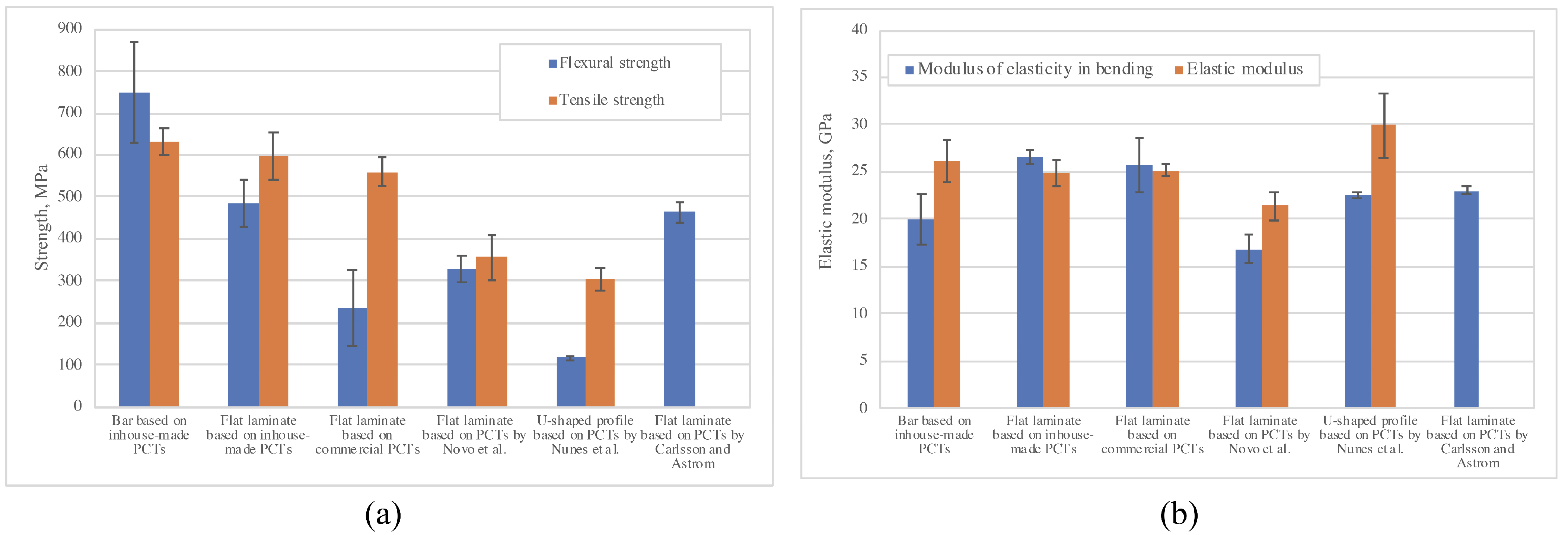
| Flexural strength [MPa] | 750 ± 118 CV = 15.7% | 485 ± 58 CV = 11.9% | 235 ± 91 CV = 38.8% | 329 ± 30 CV = 9.1% | 117 ± 4 CV = 3.7% | 465 ± 24 CV = 5.2% |
| Modulus of elasticity in bending [GPa] | 20.0 ± 2.7 CV = 13.4% | 26.6 ± 0.8 CV = 2.9% | 25.7 ± 2.9 CV = 11.3% | 16.8 ± 1.5 CV = 8.9% | 22.5 ± 0.3 CV = 1.3% | 23 ± 0.45 CV = 2% |
| Flexural strength/Fiber volume fraction [MPa] | 2206 ± 347 | 1347 ± 160 | 734 ± 285 | 1097 ± 100 | 209 ± 8 | 1329 ± 69 |
| Modulus of elasticity in bending/Fiber volume fraction [GPa] | 58.7 ± 7.9 | 73.9 ± 2.1 | 80.3 ± 9.0 | 56 ± 5 | 40.2 ± 0.5 | 65.7 ± 1.3 |
| Tensile Strength [MPa] | 632 ± 31 CV = 5.0% | 597 ± 55 CV = 9.2% | 561 ± 35 CV = 6.2% | 356 ± 53 CV = 15.0% | 305 ± 26 CV = 8.5% | - |
| Elastic modulus [GPa] | 26.2 ± 2.2 CV = 8.4% | 24.9 ± 1.4 CV = 5.6% | 25.2 ± 0.7 CV = 2.8% | 21.4 ± 1.5 CV = 7% | 29.9 ± 3.5 CV = 11.7% | - |
| Tensile Strength/Fiber volume fraction [MPa] | 1859 ± 92 | 1658 ± 153 | 1753 ± 109 | 1186 ± 177 | 545 ± 46 | - |
| Elastic modulus/Fiber volume fraction [GPa] | 77.1 ± 6.4 | 69.2 ± 3.9 | 78.8 ± 2.2 | 71.3 ± 5.0 | 53.4 ± 6.3 | - |
| Apparent interlaminar shear strength [MPa] | 19.3 ± 0.5 CV = 2.56% | 23.1 ± 1.6 CV = 6.87% | 18.1 ± 3.4 CV = 18.8% | - | - | - |
| Cross-section of a composite profile and its dimension [mm] | bar Ø 6 | flat laminate 75 × 3.5 | flat laminate 75 × 3.5 | flat laminate 20 × 3 | U-shaped profile 24 × 4 × 2 | flat laminate 30 × 3 |
Publisher’s Note: MDPI stays neutral with regard to jurisdictional claims in published maps and institutional affiliations. |
© 2022 by the authors. Licensee MDPI, Basel, Switzerland. This article is an open access article distributed under the terms and conditions of the Creative Commons Attribution (CC BY) license (https://creativecommons.org/licenses/by/4.0/).
Share and Cite
Vedernikov, A.; Minchenkov, K.; Gusev, S.; Sulimov, A.; Zhou, P.; Li, C.; Xian, G.; Akhatov, I.; Safonov, A. Effects of the Pre-Consolidated Materials Manufacturing Method on the Mechanical Properties of Pultruded Thermoplastic Composites. Polymers 2022, 14, 2246. https://doi.org/10.3390/polym14112246
Vedernikov A, Minchenkov K, Gusev S, Sulimov A, Zhou P, Li C, Xian G, Akhatov I, Safonov A. Effects of the Pre-Consolidated Materials Manufacturing Method on the Mechanical Properties of Pultruded Thermoplastic Composites. Polymers. 2022; 14(11):2246. https://doi.org/10.3390/polym14112246
Chicago/Turabian StyleVedernikov, Alexander, Kirill Minchenkov, Sergey Gusev, Artem Sulimov, Ping Zhou, Chenggao Li, Guijun Xian, Iskander Akhatov, and Alexander Safonov. 2022. "Effects of the Pre-Consolidated Materials Manufacturing Method on the Mechanical Properties of Pultruded Thermoplastic Composites" Polymers 14, no. 11: 2246. https://doi.org/10.3390/polym14112246
APA StyleVedernikov, A., Minchenkov, K., Gusev, S., Sulimov, A., Zhou, P., Li, C., Xian, G., Akhatov, I., & Safonov, A. (2022). Effects of the Pre-Consolidated Materials Manufacturing Method on the Mechanical Properties of Pultruded Thermoplastic Composites. Polymers, 14(11), 2246. https://doi.org/10.3390/polym14112246