
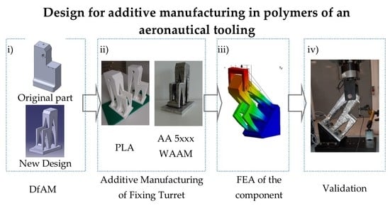
Validation of the Mechanical Behavior of an Aeronautical Fixing Turret Produced by a Design for Additive Manufacturing (DfAM)

 ,
,  ,
,  , ,
, ,
Abstract
:
1. Introduction
2. Materials and Methods
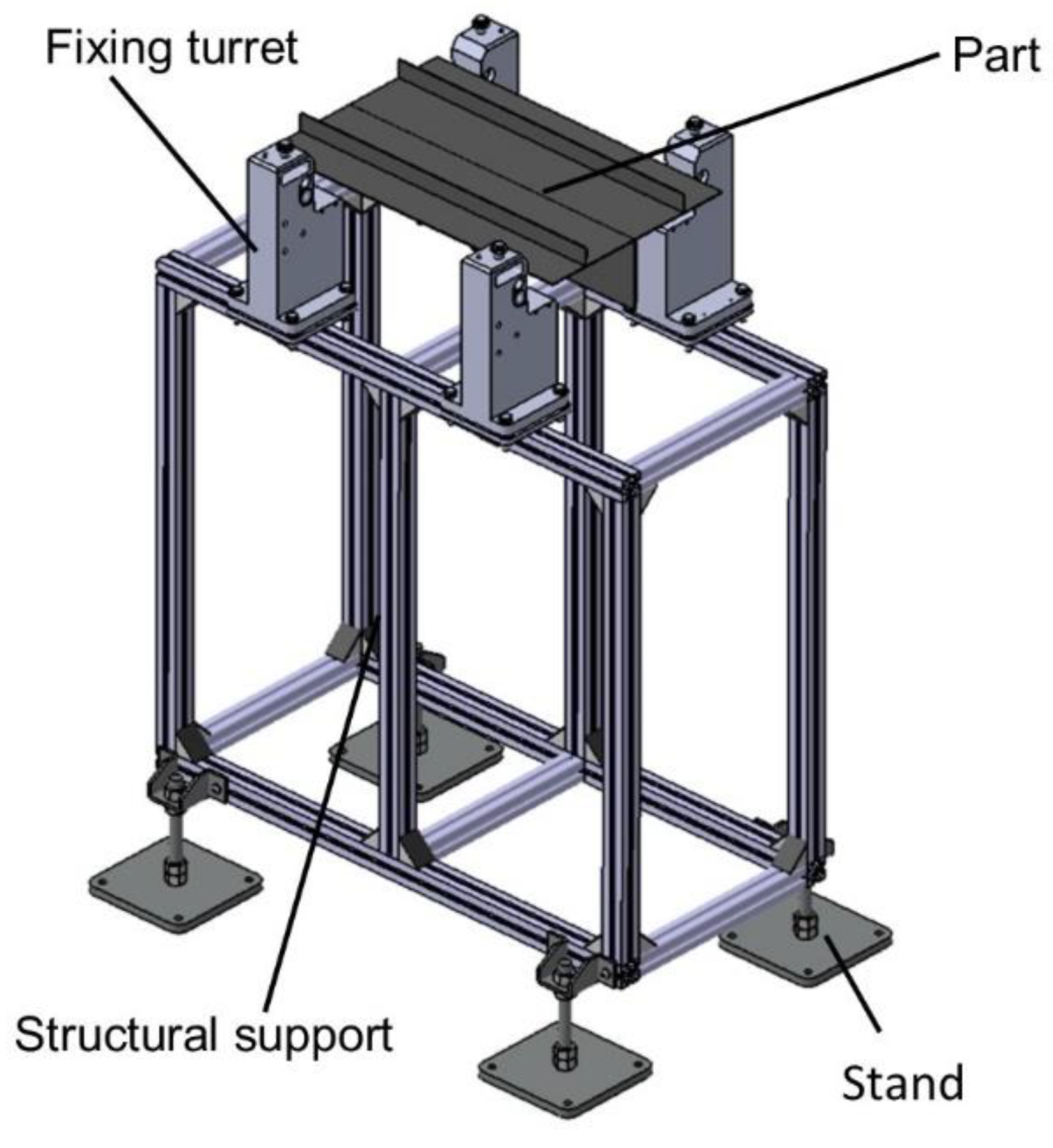
2.1. Case Study: Fixing Turret
2.2. Design for Additive Manufacturing (DfAM) Methodology
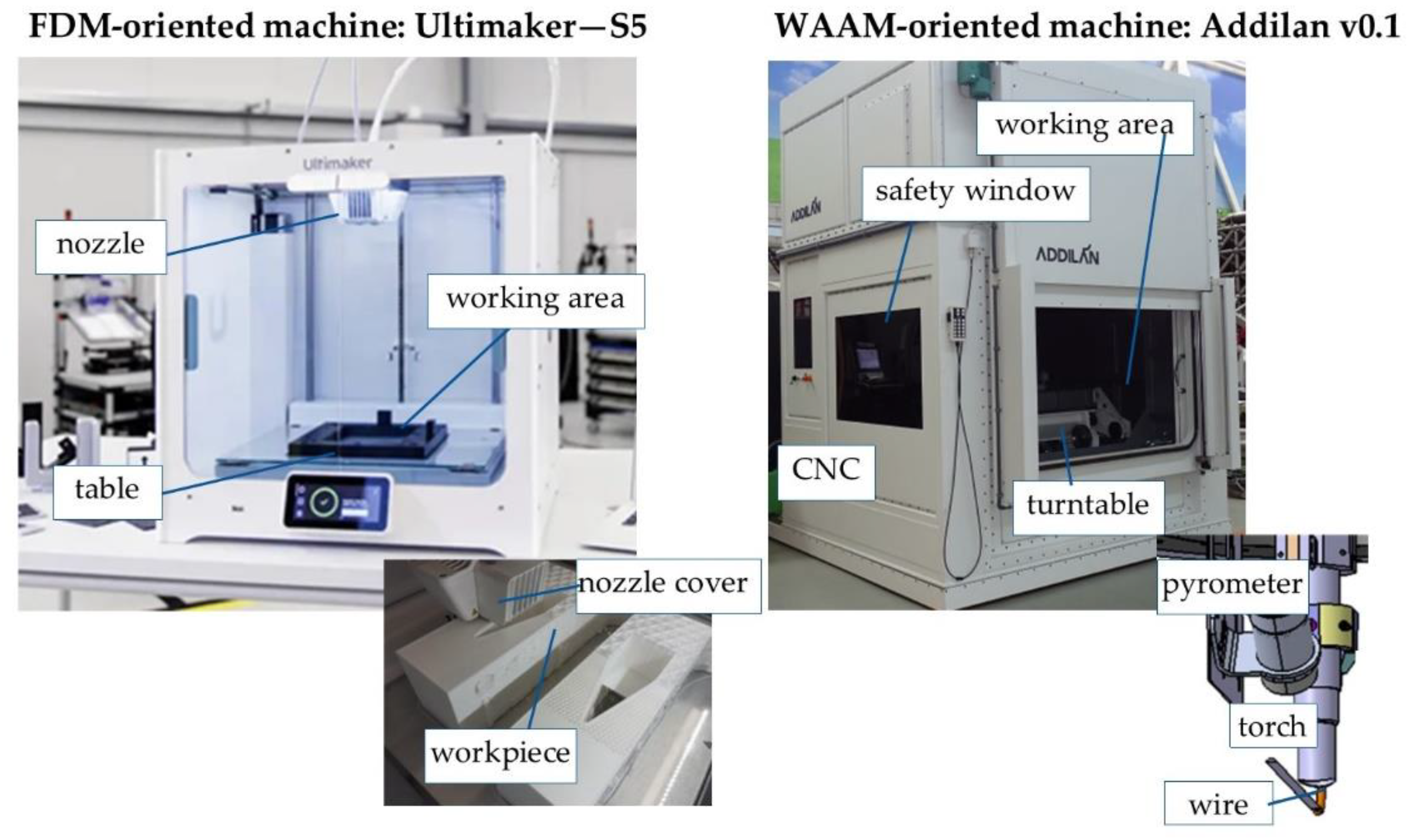
2.3. Additive Manufacturing: Material, Machine and Parameters
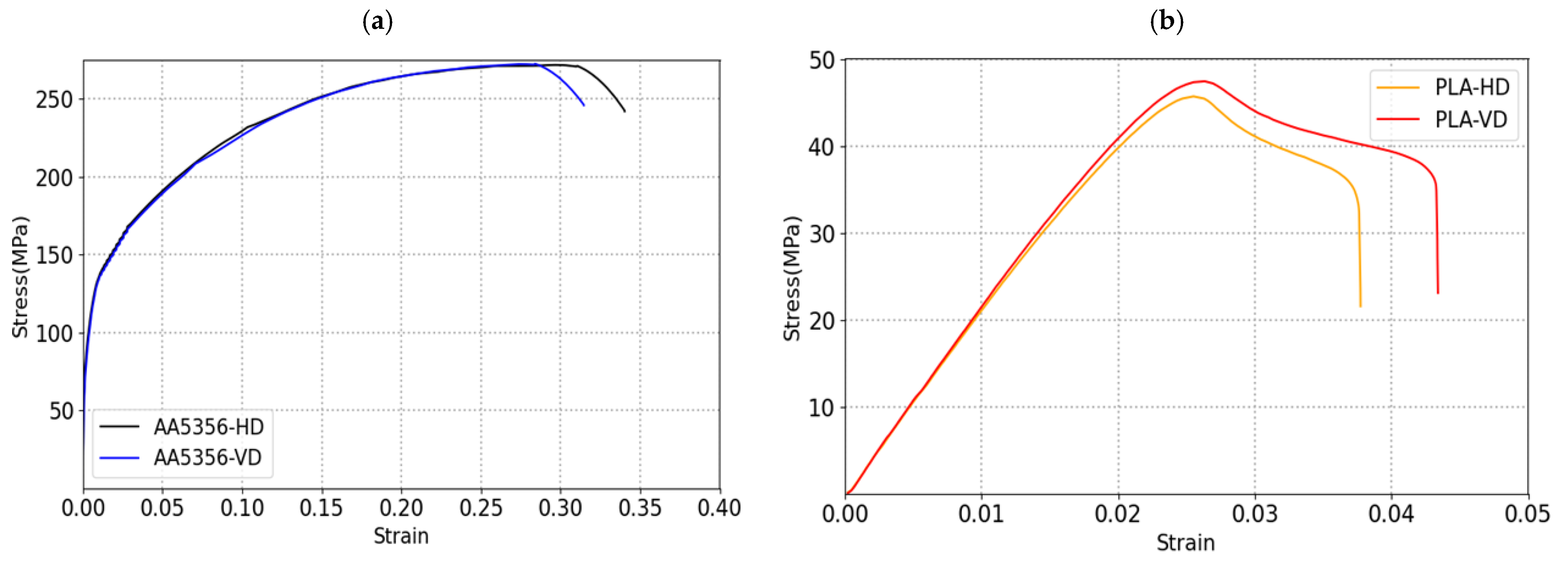
2.4. Mechanical Characterization
2.5. Mechanical Behaviour Testing
3. Results
3.1. Design for Additive Manufacturing (DfAM) Methodology
3.2. Additive Manufacturing of the Fixing Turret
3.3. Finite Element Analysis (FEA) of the Mechanical Behavior of the Fixing Turret
4. Discussion
Validation of Mechanical Testing: Comparison of the PLA and WAAM-AA5356 Parts
5. Conclusions
- Initially, the material manufactured by AM was characterized by means of specimens designed for this purpose. The mechanical properties reported for the PLA manufactured by FDM are YS 43 MPa, UTS 47 MPa and elongation of 41% of mean; for the case of AA5356 manufactured by WAAM, they are YS 147 MPa, UTS 270 MPa and elongation of 79% of mean with a higher anisotropy in the results.
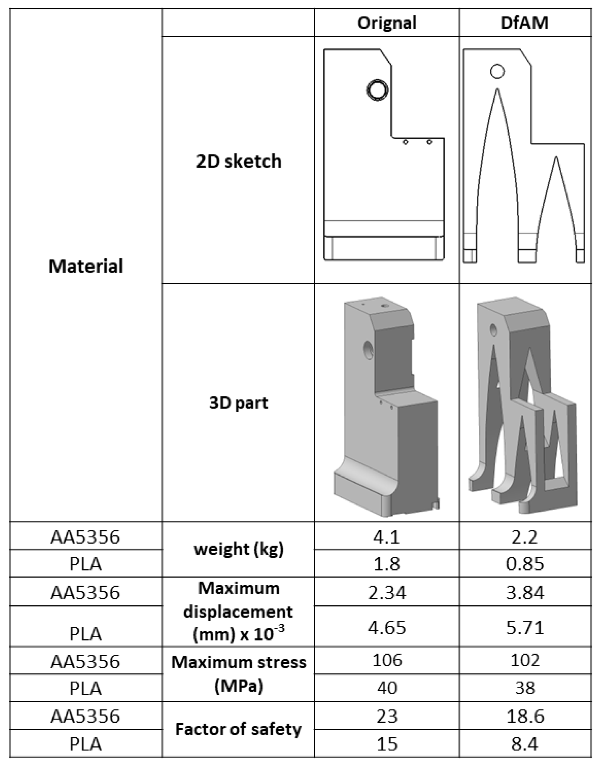
- A design solution based on arches was adopted, a solution aimed at lightening the parts. This design was applied to an aeronautical turret. The reasoning behind the design is inspired by civil structures. The result is a part that is approximately 50% lighter than the original part.
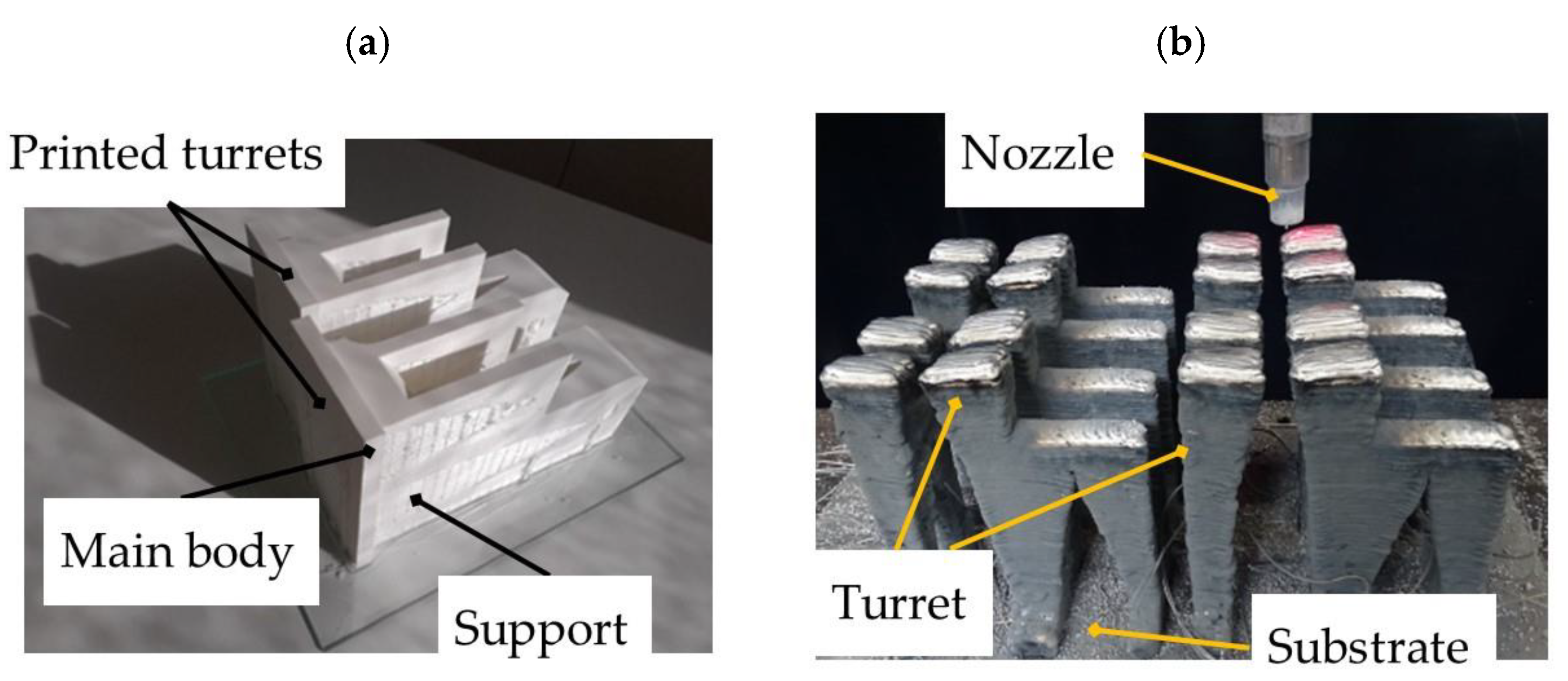
- It was manufactured with a matrix strategy to optimize manufacturing times, especially in WAAM. This technology is faster in the manufacture of the part with less geometric accuracy.
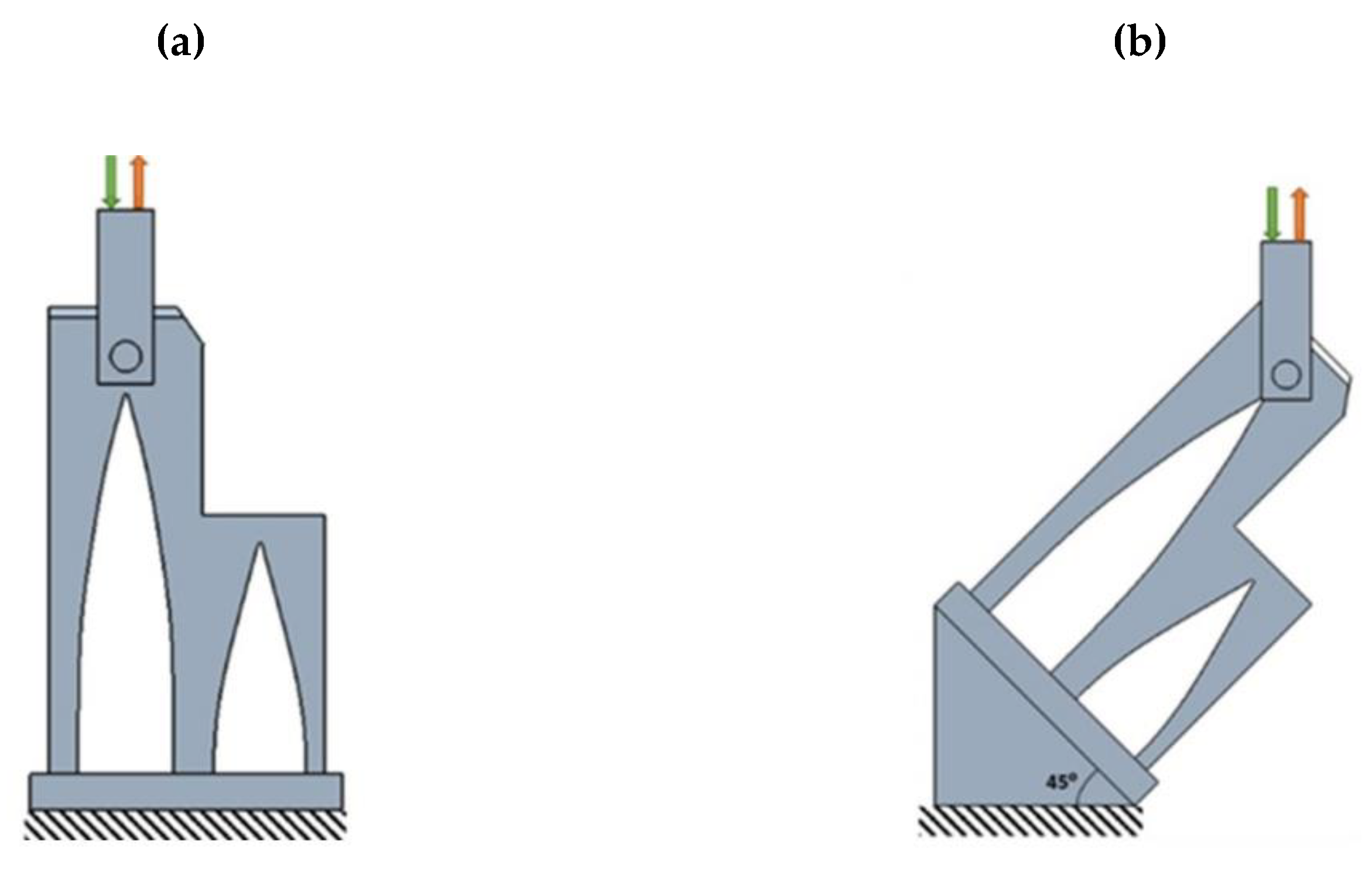
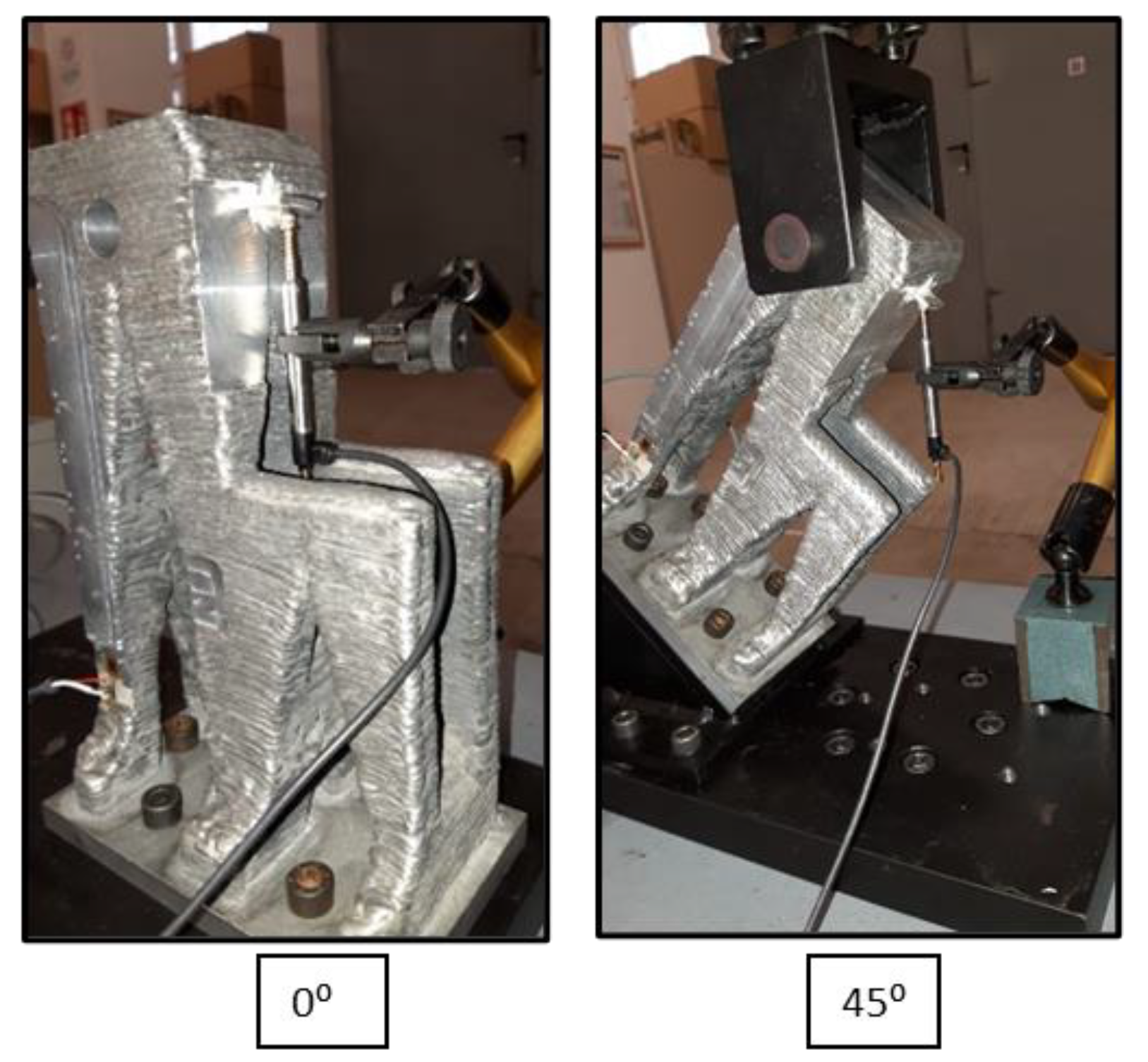
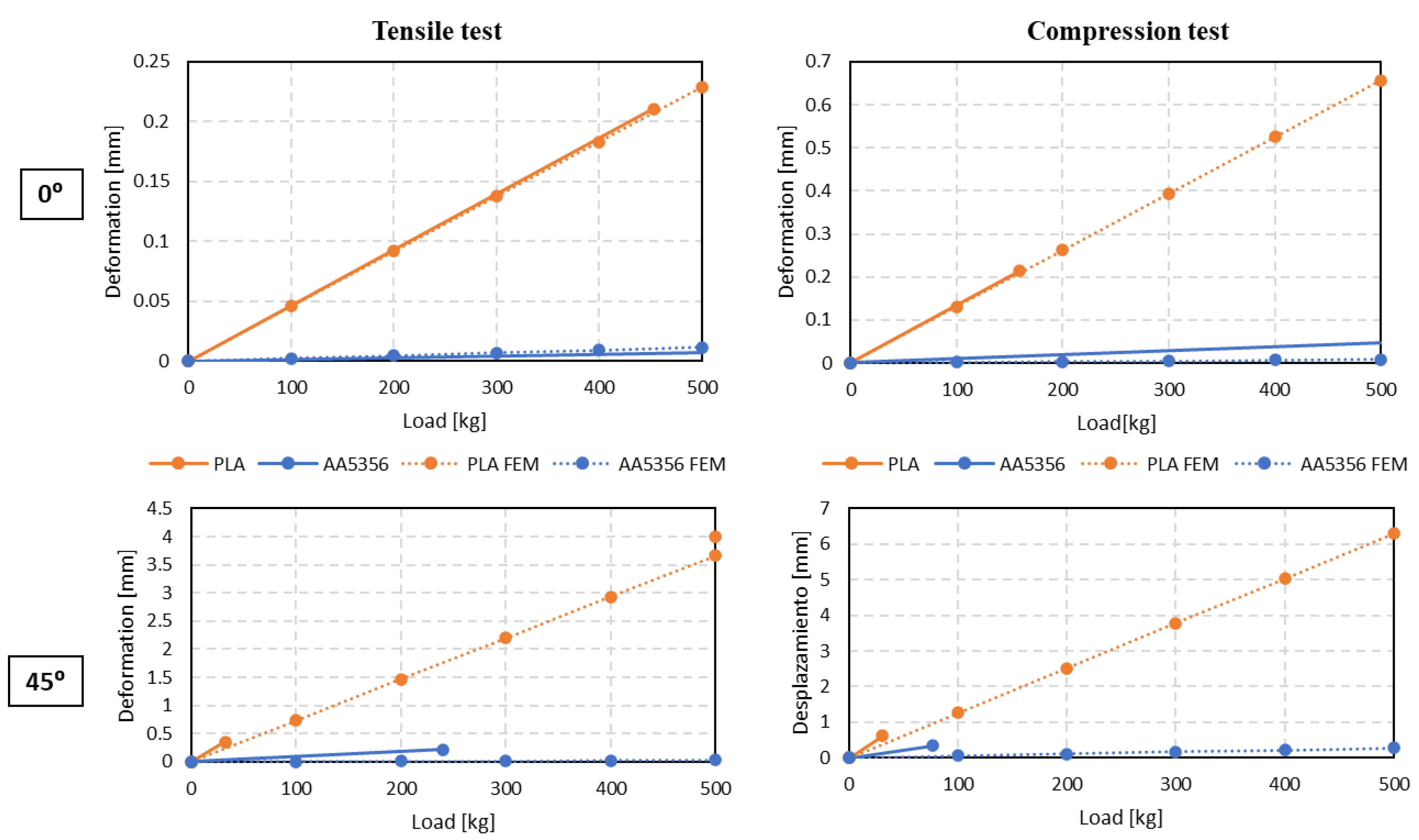
- The mechanical behavior of the parts manufactured by PLA and WAAM was simulated and validated with experimental tests. It was observed that the model is capable of estimating the observable deformations in the real part.
- The mechanical behavior of the part is better in metal fabrication with WAAM in aluminum for its mechanical properties, although the polymeric solution in PLA by FDM could be sufficient in some application cases and for parts where light weighting is a critical constraint.
Author Contributions
Funding
Institutional Review Board Statement
Informed Consent Statement
Data Availability Statement
Conflicts of Interest
References
- Czerny, A.I.; Fu, X.; Lei, Z.; Oum, T.H. Post pandemic aviation market recovery: Experience and lessons from China. J. Air Transp. Manag. 2021, 90, 101971. [Google Scholar] [CrossRef]
- Papanikos, G.T. Europe, Ukraine and Russia: What is Really at Stake? Available online: https://www.researchgate.net/publication/358904290_Europe_Ukraine_and_Russia_What_is_Really_at_Stake (accessed on 21 April 2022).
- Akbar, M.; Irohara, T. Scheduling for sustainable manufacturing: A review. J. Clean. Prod. 2018, 205, 866–883. [Google Scholar] [CrossRef]
- Gollakota, A.R.; Shu, C.M. COVID-19 and Energy sector–Unique opportunity for switching to clean energy. Gondwana Res. 2022, in press. [Google Scholar] [CrossRef] [PubMed]
- Adamietz, R.; Giesen, T.; Mayer, P.; Johnson, A.; Bibb, R.; Seifarth, C. Reconfigurable and transportable container-integrated production system. Robot. Comput. Integr. Manuf. 2018, 53, 1–20. [Google Scholar] [CrossRef] [Green Version]
- Bi, Z.M.; Zhang, W.J. Flexible fixture design and automation: Review, issues and future directions. Int. J. Prod. Res. 2001, 39, 2867–2894. [Google Scholar] [CrossRef]
- Kang, X.; Peng, Q. Recent research on Computer-Aided Fixture Planning. Recent Pat. Mech. Eng. 2009, 2, 8–18. [Google Scholar] [CrossRef]
- Fleischer, J.; Denkena, B.; Winfough, B.; Mori, M. Workpiece and Tool Handling in Metal Cutting Machines. CIRP Ann. 2006, 55, 817–839. [Google Scholar] [CrossRef]
- Aoy ama, T.; Kakinuma, Y. Development of Fixture Devices for Thin and Compliant Workpieces. Ann. CIRP 2005, 54, 325–328. [Google Scholar] [CrossRef]
- Teresa, A.; Suárez, A.; Veiga, F.; Braceras, I.; Tabernero, I.; Larrañaga, O.; Lamikiz, A. Wire arc additive manufacturing Ti6Al4V aeronautical parts using plasma arc welding: Analysis of heat-treatment processes in different atmospheres. J. Mater. Res. Technol. 2020, 9, 15454–15466. [Google Scholar]
- Hanssen, J.; Moe, Z.H.; Desmond, T.; Ong, Y.C. Rapid prototyping in manufacturing. In Handbook of Manufacturing Engineering and Technology; Nee, A., Ed.; Springer: London, UK, 2015; pp. 1–16. [Google Scholar]
- Gunasekaran, K.N.; Vishal Aravinth, C.B.; Kumaran, M.; Madhankumar, S.; Kumar, S.P. Investigation of mechanical properties of PLA printed material under varying infill density. Mater. Today: Proc. 2021, 45, 1849–1856. [Google Scholar] [CrossRef]
- Melnikova, R.; Ehrmann, A.; Finsterbusch, K. 3D printing of textile-based structures by Fused Deposition Modelling (FDM) with different polymer materials. In Proceedings of the 2014 Global Conference on Polymer and Composite Materials (PCM 2014), Ningbo, China, 27–29 May 2014. [Google Scholar]
- Rodrigues, T.A.; Duarte, V.; Miranda, R.M.; Santos, T.G.; Oliveira, J.P. Current status and perspectives on wire and arc additive manufacturing (WAAM). Materials 2019, 12, 1121. [Google Scholar] [CrossRef] [PubMed] [Green Version]
- Veiga, F.; Suárez, A.L.; Aldalur, E.; Goenaga, I.; Amondarain, J. Wire arc additive manufacturing process for topologically optimized aeronautical fixtures, 3D print. In 3D and Additive Manufacturing; Mary Ann Liebert, Inc.: Larchmont, NY, USA, 12 July 2021. [Google Scholar] [CrossRef]
- Jankovics, D.; Barari, A. Customization of automotive structural components using additive manufacturing and topology optimization. IFAC-PapersOnLine 2019, 52, 212–217. [Google Scholar] [CrossRef]
- Suárez, A.; Veiga, F.; Bhujangrao, T.; Aldalur, E. Study of the Mechanical Behavior of Topologically Optimized Arc Wire Direct Energy Deposition Aerospace Fixtures. J. Mater. Eng. Perform. 2022. [Google Scholar] [CrossRef]
- Aldalur, E.; Suárez, A.; Veiga, F. Metal transfer modes for Wire Arc Additive Manufacturing Al-Mg alloys: Influence of heat input in microstructure and porosity. J. Mater. Process. Technol. 2021, 297, 117271. [Google Scholar] [CrossRef]
- Suárez, A.; Aldalur, E.; Veiga, F.; Artaza, T.; Tabernero, I.; Lamikiz, A. Wire arc additive manufacturing of an aeronautic fitting with different metal alloys: From the design to the part. J. Manuf. Process. 2021, 64, 188–197. [Google Scholar] [CrossRef]
- Meng, L.; Zhang, W.; Quan, D.; Shi, G.; Tang, L.; Hou, Y.; Breitkopf, P.; Zhu, J.; Gao, T. From Topology Optimization Design to Additive Manufacturing: Today’s Success and Tomorrow’s Roadmap. Arch. Comput. Methods Eng. 2020, 27, 805–830. [Google Scholar] [CrossRef]
- Orme, M.E.; Gschweitl, M.; Ferrari, M.; Madera, I.; Mouriaux, F. Designing for Additive Manufacturing: Lightweighting Through Topology Optimization Enables Lunar Spacecraft. ASME. J. Mech. Des. 2017, 139, 100905. [Google Scholar] [CrossRef]
- Orme, M.; Madera, I.; Gschweitl, M.; Ferrari, M. Topology Optimization for Additive Manufacturing as an Enabler for Light Weight Flight Hardware. Designs 2018, 2, 51. [Google Scholar] [CrossRef] [Green Version]
- Yang, K.K.; Zhu, J.H.; Wang, C.; Jia, D.S.; Song, L.L.; Zhang, W.H. Experimental validation of 3D printed material behaviors and their influence on the structural topology design. Comput. Mech. 2018, 61, 581–598. [Google Scholar] [CrossRef]


| References | Suarez et al. [17] | Veiga et al. [15] | Current Work |
|---|---|---|---|
| Aim | The paper aims to lighten three different parts of the fixturing system by means of DfAM techniques for Additive Manifacturing (AM) with topological optimization, in different materials (polymers and metals). | This article focuses on Ref A of the previous work, which is the one used in the current paper, aiming at the actual fabrication of the part by WAAM. | This article aims to complement those previously presented. Considering and observing the limitations of the WAAM for topological optimization, a vault structure design to lighten the volume of the part is adopted. The part is manufactured using metal and polymer material. Its mechanical behavior is tested and compared with the FEM model. |
| Procedure | Commercial software based on polyNURBS was applied to topologically optimize the AM parts, and thethe topologically optimised solution was adapted. The mechanical behavior of the parts was analysed using finite element methods (FEM). | The topological optimization solution chosen in the previous work was adapted considering the constraints of the WAAM technology and by means of the characterization of the materials. The part was manufactured using different metals. | Inspired by civil engineering applications, we opted for a design in the form of arches made by hand. This type of design, more suitable for certain AM technologies, should be automated in future steps. The incorporation of polymer manufacturing allows for a more accurate part in terms of overall geometry after printing and a part with maximum lightness. |
| Design Solution | 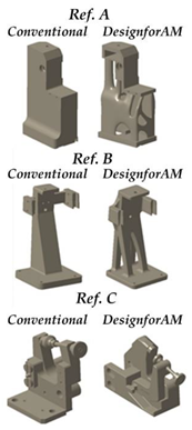 | 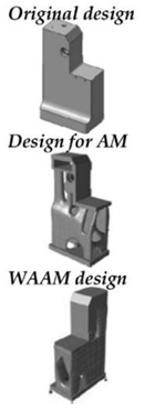 | 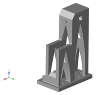 |
| Achievements | The current manufacturing solution was made lighter, the mechanical behavior of the parts was tested under different materials and load conditions. Finally, a methodology based on artificial neural networks (ANN) was developed to interpolate in other working conditions. | A methodology for the design and fabrication of an optimized and subsequently corrected real part was carried out taking into account the limitations of WAAM in several of the main weldable materials. | By carrying out these tests and manufacturing the parts, as well as adopting a new design aimed at maximum light weighting, a holistic view of the manufacture of parts of medium size and complexity is given. |
| Material | Layer Height | Wall Thickness | Filling Pattern | Filling Density | Support Pattern | Support Density | |
|---|---|---|---|---|---|---|---|
| PLA | 0.15 mm | 1.2 mm | Triangles | 100% | Triangles | 10% | |
| Material | Wire Diameter (mm) | Transfer Mode | Wire Feed Speed WFS (m/min) | Travel Speed (cm/min) | Layer Height (mm) | Current I (A) | Voltage V (V) |
| AA5356 | 1.2 | Pulsed AC | 8 | 168 | 1.5 | 128.36 | 16.61 |
| AA5356 | PLA | ||
|---|---|---|---|
| 0.2% Yield strength (MPa) | HD | 148.25 ± 5 | 42.4 ± 0.34 |
| VD | 146.88 ± 4 | 43.5 ± 0.89 | |
| UTS (MPa) | HD | 276.67 ± 3 | 46.42 ± 0.45 |
| VD | 264.33 ± 4 | 48.68 ± 0.41 | |
| Elongation (%) | HD | 81.58 ± 4 | 39.32 ± 0.09 |
| VD | 78.60 ± 3 | 42.20 ± 1.02 |
| Material | Production Time (h/part) | Deposition Rate (kg/h) | Printed Part Weight (kg/part) |
|---|---|---|---|
| AA 5356 | 5 | 1.44 | 2.22 |
| PLA | 103 | 0.01 | 0.85 |
Publisher’s Note: MDPI stays neutral with regard to jurisdictional claims in published maps and institutional affiliations. |
© 2022 by the authors. Licensee MDPI, Basel, Switzerland. This article is an open access article distributed under the terms and conditions of the Creative Commons Attribution (CC BY) license (https://creativecommons.org/licenses/by/4.0/).
Share and Cite
Veiga, F.; Bhujangrao, T.; Suárez, A.; Aldalur, E.; Goenaga, I.; Gil-Hernandez, D. Validation of the Mechanical Behavior of an Aeronautical Fixing Turret Produced by a Design for Additive Manufacturing (DfAM). Polymers 2022, 14, 2177. https://doi.org/10.3390/polym14112177
Veiga F, Bhujangrao T, Suárez A, Aldalur E, Goenaga I, Gil-Hernandez D. Validation of the Mechanical Behavior of an Aeronautical Fixing Turret Produced by a Design for Additive Manufacturing (DfAM). Polymers. 2022; 14(11):2177. https://doi.org/10.3390/polym14112177
Chicago/Turabian StyleVeiga, Fernando, Trunal Bhujangrao, Alfredo Suárez, Eider Aldalur, Igor Goenaga, and Daniel Gil-Hernandez. 2022. "Validation of the Mechanical Behavior of an Aeronautical Fixing Turret Produced by a Design for Additive Manufacturing (DfAM)" Polymers 14, no. 11: 2177. https://doi.org/10.3390/polym14112177
APA StyleVeiga, F., Bhujangrao, T., Suárez, A., Aldalur, E., Goenaga, I., & Gil-Hernandez, D. (2022). Validation of the Mechanical Behavior of an Aeronautical Fixing Turret Produced by a Design for Additive Manufacturing (DfAM). Polymers, 14(11), 2177. https://doi.org/10.3390/polym14112177