
Wood Dust Flammability Analysis by Microscale Combustion Calorimetry


 ,
, 

Abstract
:1. Introduction
2. Experiment Arrangement
2.1. Test Method
- Sample heating rate: 0.1–10 K s−1
- Gas flow rate: 50 to 200 cm3 min−1, response time of <0.1 s, sensitivity of 0.1% of full scale.
- Repeatability is ±0.2% of full scale and an accuracy of ±1% of full-scale deflection.
- Sample size: 0.5–50 mg (milligrams).
- Detection limit: 5 mW.
- Repeatability: ±2% (10 mg specimen).
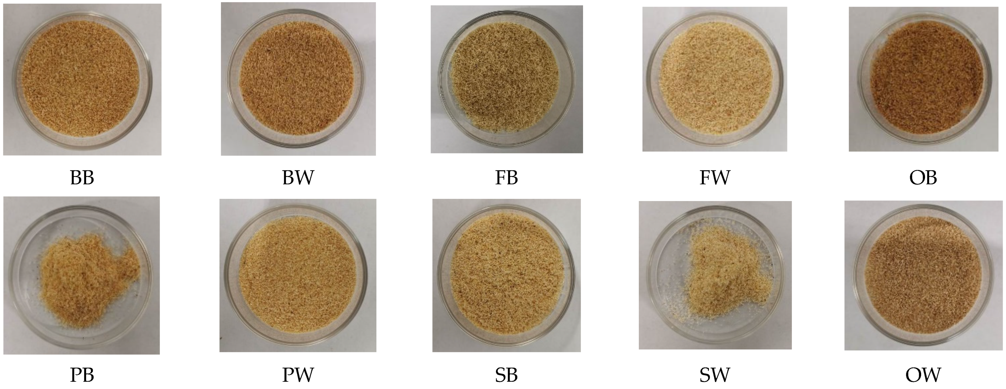
2.2. Materials
3. Analysis of Test Results
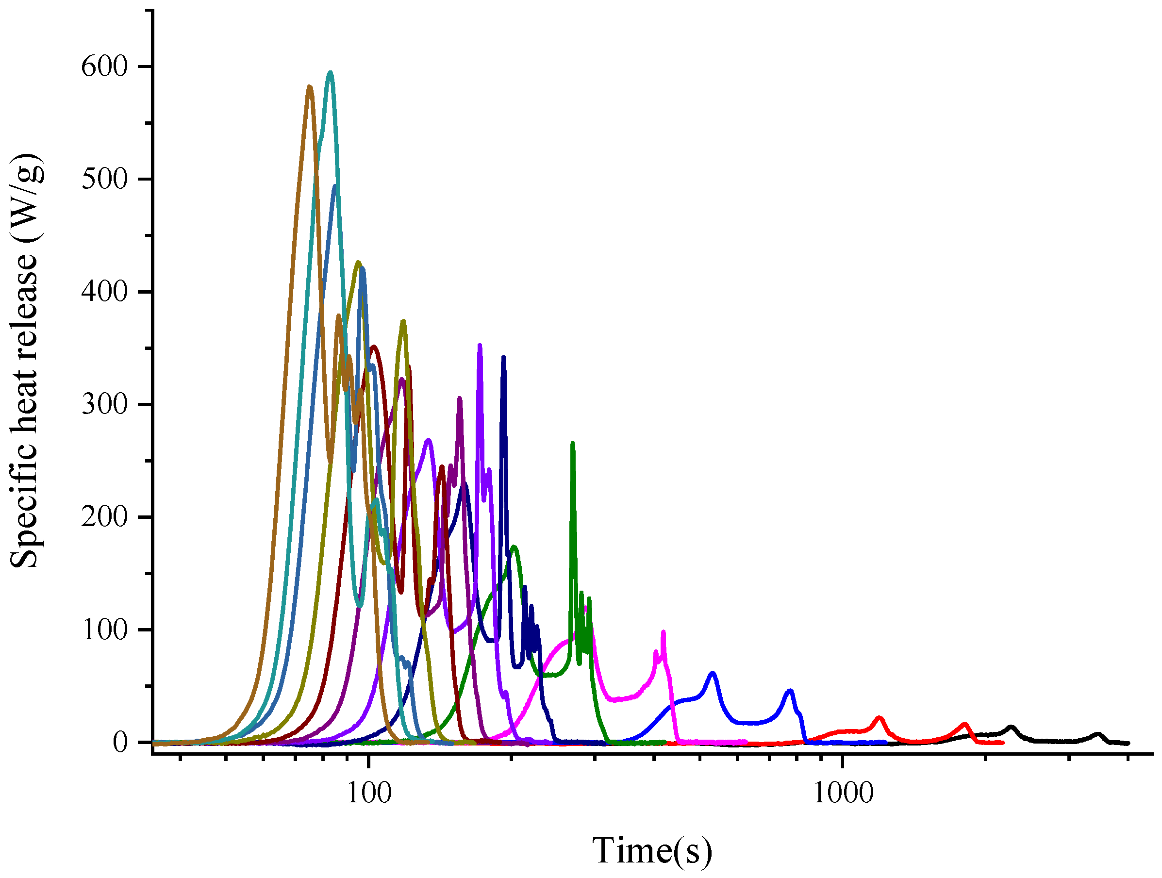
3.1. Curve Shape Observations of Method A and Method B
3.2. Typical Parameters Directly from Method A and Method B
3.3. Derived Parameters from MCC Tests
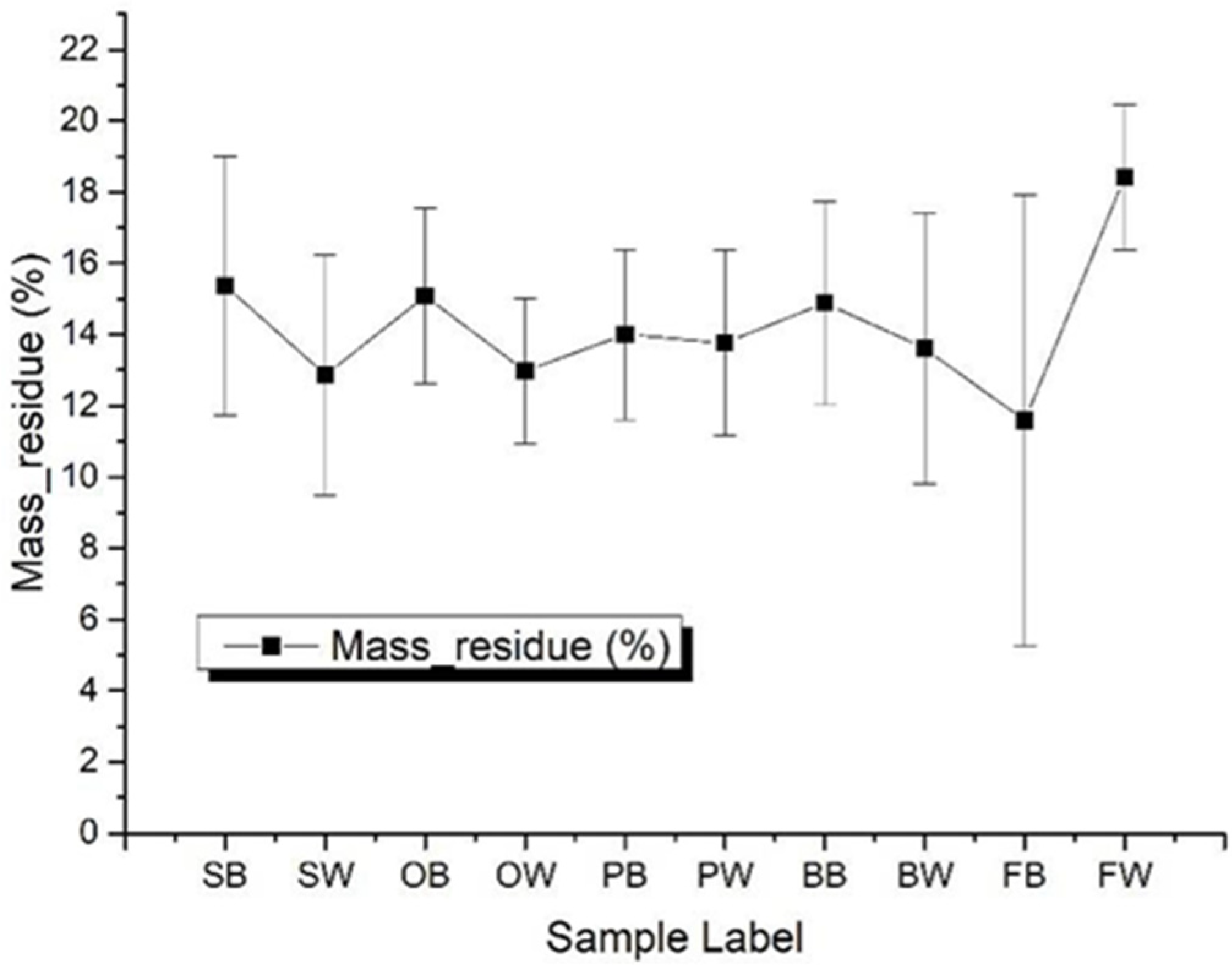
3.3.1. Total Heat Release
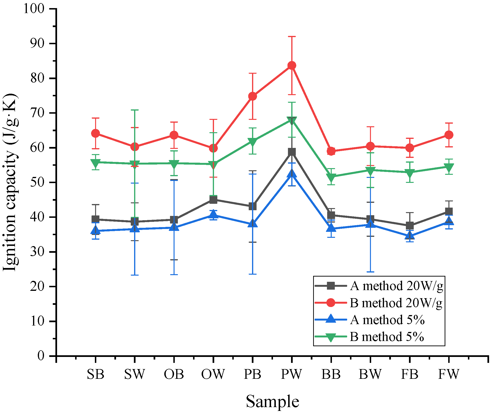
3.3.2. Ignition Capacity
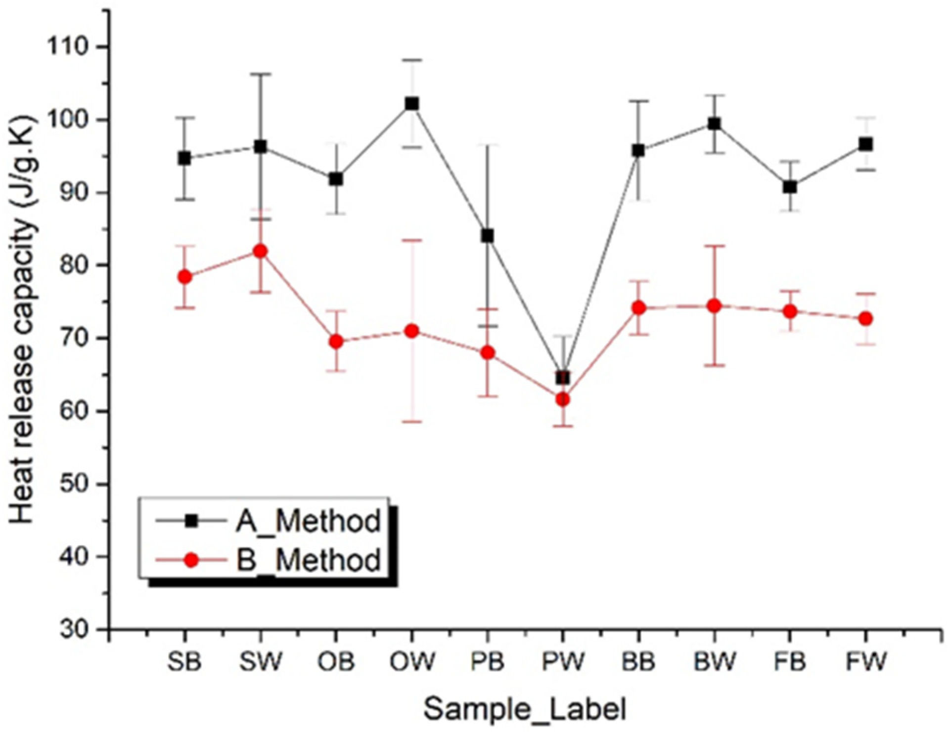
3.3.3. Heat Release Capacity
4. Conclusions
- The experimental results obtained by Methods A and B are different, which are mainly manifested in the curves of the heat release rate curve, total heat released, peak temperatures, peak heat release rates, etc. The parameter peak values of Method A are higher than those of Method B, and the corresponding temperatures are also higher than those of Method B.
- The total released heat of Method B is close to that obtained by the oxygen boom combustion method. So, Method B has more possibility of replacing the oxygen boom method compared with Method A. The predicted value of the combustion heat obtained from Method B is more reliable since the total heat released by Method B is more referable.
- MCC combustion experiments with heating rates of 5.5 K s−1 are close to real burning face heating rates during polymer burning. Peak heat release at 4.0, 4.5, 5.0, 5.5 K s−1 reaches the heat release upper limits for these wood MCC experiments, which can be reflected in the oxygen content during the experiment, the oxygen concentration is still more than the 10% specified by MCC experimental procedure.
Author Contributions
Funding
Institutional Review Board Statement
Informed Consent Statement
Acknowledgments
Conflicts of Interest
References
- Martiniaková, M.; Omelka, R.; Jancová, A.; Stawarz, R.; Formicki, G. Heavy metal content in the femora of yellow-necked mouse (Apodemus flavicollis) and wood mouse (Apodemus sylvaticus) from different types of polluted environment in Slovakia. Environ. Monit. Assess. 2010, 171, 651–660. [Google Scholar] [CrossRef] [PubMed]
- Callé, S.; Klaba, L.; Thomas, D.; Perrin, L.; Dufaud, O. Influence of the size distribution and concentration on wood dust explosion: Experiments and reaction modelling. Powder Technol. 2005, 157, 144–148. [Google Scholar] [CrossRef]
- Huang, C.; Chen, X.; Yuan, B.; Zhang, H.; Dai, H.; He, S.; Zhang, Y.; Niu, Y.; Shen, S. Suppression of wood dust explosion by ultrafine magnesium hydroxide. J. Hazard. Mater. 2019, 378, 120723. [Google Scholar] [CrossRef] [PubMed]
- Jiang, L.; Zhang, D.; Li, M.; He, J.-J.; Gao, Z.-H.; Zhou, Y.; Sun, J.-H. Pyrolytic behavior of waste extruded polystyrene and rigid polyurethane by multi kinetics methods and Py-GC/MS. Fuel 2018, 222, 11–20. [Google Scholar] [CrossRef]
- Li, M.; Liu, L.; Jiang, L.; Gou, F.-H.; Sun, J.-H. Application of distributed activation energy models to polymer pyrolysis: Effects of distributed model selection, characteristics, validation, and sensitivity analysis. Fuel 2019, 254, 115594. [Google Scholar] [CrossRef]
- Jiang, L.; Xiao, H.H.; He, J.J.; Sun, Q.; Gong, L.; Sun, J.H. Application of genetic algorithm to pyrolysis of typical polymers. Fuel Process. Technol. 2015, 138, 48–55. [Google Scholar] [CrossRef]
- Alhassan, M.O.; Jiang, L.; Mensah, R.A.; Xu, Q.; Osei, M.B. Novel Approaches to Modelling Flammability Characteristics of Polymethyl Methacrylate (PMMA) via Multivariate Adaptive Regression Splines and Random Forest Methods. Asian J. Res. Comput. Sci. 2019, 4, 1–14. [Google Scholar] [CrossRef] [Green Version]
- Lyon, R.E. Isokinetic Analysis of Reaction Onsets. Thermochim. Acta 2021, 708, 179117. [Google Scholar] [CrossRef]
- Lyon, R.E.; Safronava, N.; Crowley, S.; Walters, R. A molecular-level fire growth parameter. Polym. Degrad. Stab. 2021, 186, 109478. [Google Scholar] [CrossRef]
- Xu, Q.; Jin, C.; Jiang, Y. Analysis of the relationship between MCC and thermal analysis results in evaluating flammability of EPS foam. J. Therm. Anal. Calorim. 2014, 118, 687–693. [Google Scholar] [CrossRef]
- Asante-Okyere, S.; Xu, Q.; Mensah, R.A.; Jin, C.; Ziggah, Y.Y. Generalized regression and feed forward back propagation neural networks in modelling flammability characteristics of polymethyl methacrylate (PMMA). Thermochim. Acta 2018, 667, 79–92. [Google Scholar] [CrossRef]
- Mensah, R.A.; Xu, Q.; Asante-Okyere, S.; Jin, C.; Bentum-Micah, G. Correlation analysis of cone calorimetry and microscale combustion calorimetry experiments. J. Therm. Anal. Calorim. 2019, 136, 589–599. [Google Scholar] [CrossRef]
- Xu, Q.; Jin, C.; Griffin, G.J.; Matala, A.; Hostikka, S. A PMMA flammability analysis using the MCC. J. Therm. Anal. Calorim. 2016, 126, 1831–1840. [Google Scholar] [CrossRef]
- Lyon, R.E.; Walters, R.N.; Stoliarov, S.I. Screening flame retardants for plastics using microscale combustion calorimetry. Polym. Eng. Sci. 2007, 47, 1501–1510. [Google Scholar] [CrossRef]
- Stoliarov, S.; Smith, K.D.; Westmoreland, P.R.; Lyon, R.; Nyden, M. A New Reactive Molecular Dynamics Model of Polymer Pyrolysis. In Proceedings of the BCC Conference Annual 18th 2007 Recent Advances in Flame Retardancy of Polymeric Materials|BCC|, Stamford, CT, USA, 20–23 May 2007. [Google Scholar]
- Lyon, R.E.; Crowley, S. Fire properties of combustible materials from unsteady burning. Fire Saf. J. 2021, 120, 103054. [Google Scholar] [CrossRef]
- Zhuge, J.; Chen, X.; Ks, A.; Manica, D.P. Microscale combustion calorimeter-application and limitation. Fire Mater. 2016, 40, 987–998. [Google Scholar] [CrossRef]
- Sonnier, R.; Vahabi, H.; Ferry, L.; Lopez-Cuesta, J.-M. Pyrolysis-Combustion Flow Calorimetry: A Powerful Tool to Evaluate the Flame Retardancy of Polymers. In Fire and Polymers VI: New Advances in Flame Retardant Chemistry and Science; ACS Symposium Series; ACS: Washington, DC, USA, 2012; Chapter 24. [Google Scholar]
- ASTM Standard D7309; Standard Test Method for Determining Flammability Characteristics of Plastics and Other Solid Materials Using Microscale Combustion Calorimetry. ASTM International: West Conshohocken, PA, USA, 2013.
- ISO 1928:2009; Solid Mineral Fuels—Determination of Gross Calorific Value by the Bomb Calorimetric Method and Calculation of Net Calorific Value. ISO: Geneva, Switzerland, 2009.
- Yang, C.Q.; He, Q. Textile heat release properties measured by microscale combustion calorimetry: Experimental repeatability. Fire Mater. 2012, 36, 127–137. [Google Scholar] [CrossRef]
- Solorzano, J.A.P.; Moinuddin, K.A.M.; Tretsiakova-Mcnally, S.; Joseph, P. A Study of the Thermal Degradation and Combustion Characteristics of Some Materials Commonly Used in the Construction Sector. Polymers 2019, 11, 1833. [Google Scholar] [CrossRef] [Green Version]
- Keshavarz, M.H.; Dashtizadeh, A.; Motamedoshariati, H.; Soury, H. A simple model for reliable prediction of the specific heat release capacity of polymers as an important characteristic of their flammability. J. Therm. Anal. Calorim. 2017, 128, 417–426. [Google Scholar] [CrossRef]
- Xu, Q.; Jin, C.; Majlingova, A.; Zachar, M.; Restas, A. Evaluate the flammability of a PU foam with double-scale analysis. J. Therm. Anal. Calorim. 2018, 135, 3329–3337. [Google Scholar] [CrossRef]
- Xu, Q.; Jin, C.; Majlingova, A.; Restas, A. Discuss the heat release capacity of polymer derived from microscale combustion calorimeter. J. Therm. Anal. Calorim. 2017, 133, 649–657. [Google Scholar] [CrossRef]
- Xu, Q.; Jin, C.; Jiang, Y. Compare the flammability of two extruded polystyrene foams with micro-scale combustion calorimeter and cone calorimeter tests. J. Therm. Anal. Calorim. 2017, 127, 2359–2366. [Google Scholar] [CrossRef]


| Sample Type | Label | H0(8) | Se | H0 (0) | Se | Hu(8) | Se | Hu(0) | Se |
|---|---|---|---|---|---|---|---|---|---|
| Spruce with bark | SB | 17.8 | 0.31 | 19.3 | 0.34 | 16.3 | 0.31 | 18.0 | 0.34 |
| Spruce without bark | SW | 17.4 | 0.38 | 18.7 | 0.41 | 15.8 | 0.38 | 17.4 | 0.41 |
| Oak with bark | OB | 17.0 | 0.18 | 18.4 | 0.20 | 15.6 | 0.18 | 17.1 | 0.19 |
| Oak without bark | OW | 17.7 | 0.11 | 19.2 | 0.12 | 16.3 | 0.11 | 17.9 | 0.12 |
| Pine with bark | PB | 17.7 | 0.14 | 19.2 | 0.18 | 16.4 | 0.20 | 17.9 | 0.30 |
| Pine without bark | PW | 17.5 | 0.05 | 19.0 | 0.10 | 16.1 | 0.12 | 17.6 | 0.20 |
| Beech with bark | BB | 16.2 | 0.19 | 17.6 | 0.17 | 14.8 | 0.19 | 15.8 | 0.68 |
| Beech without bark | BW | 16.0 | 0.08 | 17.5 | 0.07 | 14.6 | 0.08 | 16.2 | 0.09 |
| Fir with bark | FB | 18.4 | 0.10 | 19.9 | 0.10 | 16.9 | 0.10 | 18.6 | 0.12 |
| Fir without bark | FW | 18.1 | 0.10 | 19.7 | 0.09 | 16.7 | 0.10 | 18.3 | 0.13 |
| Method | β (K/s) | 0.1 | 0.2 | 0.5 | 1.0 | 1.5 | 2.0 | 2.5 | 3.0 | 3.5 | 4.0 | 4.5 | 5.0 | 5.5 | |
|---|---|---|---|---|---|---|---|---|---|---|---|---|---|---|---|
| BB | A | Qmax | 16.3 | 32.0 | 73.4 | 136.4 | 217.5 | 276.0 | 324.0 | 395.9 | 420.9 | 449.6 | 524.7 | 585.9 | 597.0 |
| Tmax | 340.4 | 350.2 | 368.5 | 381.5 | 392.9 | 399.4 | 404.0 | 410.8 | 412.6 | 419.7 | 423.6 | 426.4 | 422.7 | ||
| B | Qmax° | 14.1 | 22.2 | 61.6 | 120.0 | 173.8 | 231.3 | 269.5 | 322.4 | 353.8 | 427.4 | 494.2 | 598.4 | 583.7 | |
| Tmax° | 307.8 | 319.9 | 341.3 | 357.3 | 362.5 | 367.9 | 374.4 | 385.2 | 377.3 | 389.3 | 383.9 | 403.9 | 399.5 | ||
| BW | A | Qmax | 18.6 | 32.0 | 71.9 | 137.9 | 212.3 | 265.3 | 325.5 | 397.7 | 447.9 | 472.7 | 567.3 | 620.0 | 699.2 |
| Tmax | 337.8 | 349.6 | 369.4 | 383.0 | 391.2 | 398.6 | 404.1 | 407.9 | 413.8 | 415.0 | 421.7 | 420.7 | 427.2 | ||
| B | Qmax° | 13.9 | 26.8 | 57.1 | 109.8 | 191.0 | 197.6 | 271.3 | 321.4 | 357.1 | 438.2 | 527.0 | 519.2 | 522.4 | |
| Tmax° | 308.2 | 322.5 | 340.8 | 355.8 | 366.2 | 375.8 | 379.4 | 386.8 | 391.8 | 388.2 | 393.0 | 402.4 | 399.5 | ||
| SB | A | Qmax | 14.1 | 23.1 | 69.4 | 134.0 | 192.7 | 248.1 | 293.5 | 357.6 | 380.4 | 479.0 | 547.9 | 611.8 | 664.9 |
| Tmax | 341.5 | 354.4 | 374.3 | 388.8 | 398.7 | 404.4 | 409.7 | 417.1 | 422.4 | 417.6 | 427.9 | 429.0 | 432.4 | ||
| B | Qmax° | 16.3 | 29.1 | 83.1 | 163.1 | 237.5 | 294.0 | 351.2 | 413.6 | 478.9 | 543.5 | 636.2 | 688.7 | 693.5 | |
| Tmax° | 312.9 | 326.1 | 347.2 | 361.9 | 370.1 | 379.7 | 387.8 | 390.1 | 394.0 | 399.0 | 403.8 | 398.5 | 408.5 | ||
| SW | A | Qmax | 16.4 | 29.9 | 73.1 | 142.3 | 188.9 | 264.0 | 327.7 | 322.0 | 460.3 | 510.9 | 497.6 | 569.0 | 644.9 |
| Tmax | 350.0 | 363.5 | 383.5 | 397.8 | 406.9 | 412.6 | 419.3 | 426.4 | 430.4 | 434.3 | 438.9 | 440.0 | 439.4 | ||
| B | Qmax° | 27.2 | 55.9 | 107.9 | 209.4 | 301.5 | 412.1 | 430.8 | 531.4 | 588.1 | 628.1 | 757.2 | 828.7 | 819.4 | |
| Tmax° | 314.5 | 327.3 | 351.0 | 366.5 | 382.0 | 388.1 | 399.4 | 398.6 | 407.2 | 408.9 | 414.3 | 408.2 | 423.2 | ||
| OB | A | Qmax | 18.4 | 25.5 | 55.0 | 123.0 | 170.2 | 234.7 | 290.4 | 336.0 | 397.9 | 406.9 | 467.9 | 508.3 | 524.6 |
| Tmax | 327.3 | 342.9 | 354.1 | 369.3 | 374.7 | 382.9 | 388.3 | 393.4 | 390.7 | 399.2 | 402.3 | 404.9 | 409.4 | ||
| B | Qmax° | 38.1 | 30.3 | 70.7 | 136.5 | 220.5 | 291.5 | 350.3 | 384.5 | 447.0 | 492.2 | 558.6 | 624.3 | 676.2 | |
| Tmax° | 311.1 | 317.3 | 335.7 | 348.0 | 363.6 | 364.4 | 376.8 | 380.3 | 381.0 | 379.3 | 383.7 | 389.9 | 391.5 | ||
| OW | A | Qmax | 12.5 | 30.4 | 71.3 | 148.8 | 201.8 | 262.4 | 328.2 | 397.8 | 415.4 | 465.3 | 545.3 | 586.0 | 658.6 |
| Tmax | 346.9 | 357.1 | 373.0 | 390.0 | 396.5 | 404.6 | 408.5 | 414.6 | 416.5 | 420.7 | 423.4 | 427.6 | 429.4 | ||
| B | Qmax° | 21.7 | 48.5 | 94.0 | 180.2 | 250.8 | 316.7 | 395.3 | 420.1 | 484.1 | 524.9 | 600.5 | 687.0 | 666.9 | |
| Tmax° | 310.2 | 322.9 | 345.4 | 357.3 | 373.2 | 379.9 | 383.9 | 396.8 | 401.8 | 403.0 | 406.8 | 409.5 | 408.3 | ||
| PB | A | Qmax | 14.7 | 25.9 | 67.5 | 121.1 | 196.0 | 252.0 | 303.0 | 354.3 | 404.2 | 461.8 | 484.3 | 535.5 | 576.3 |
| Tmax | 351.4 | 363.9 | 382.3 | 395.7 | 407.8 | 410.8 | 418.3 | 422.0 | 428.3 | 433.3 | 437.5 | 439.7 | 444.0 | ||
| B | Qmax° | 22.2 | 40.2 | 85.6 | 189.1 | 273.8 | 342.1 | 397.1 | 485.6 | 536.5 | 599.0 | 606.8 | 629.2 | 709.3 | |
| Tmax° | 312.8 | 326.7 | 349.9 | 366.2 | 376.7 | 385.4 | 388.5 | 394.0 | 399.2 | 402.9 | 407.4 | 407.2 | 418.6 | ||
| PW | A | Qmax | 21.9 | 26.3 | 64.5 | 123.2 | 199.4 | 259.6 | 302.0 | 359.0 | 378.9 | 486.3 | 523.4 | 562.1 | 616.7 |
| Tmax | 347.8 | 363.1 | 383.5 | 397.8 | 407.6 | 416.0 | 423.0 | 427.2 | 430.7 | 436.5 | 437.8 | 441.1 | 443.8 | ||
| B | Qmax° | 17.3 | 34.5 | 79.6 | 173.2 | 235.3 | 343.4 | 409.7 | 431.6 | 517.1 | 554.3 | 662.9 | 636.9 | 674.8 | |
| Tmax° | 315.0 | 329.0 | 351.4 | 370.0 | 381.7 | 392.5 | 395.9 | 403.8 | 406.4 | 408.9 | 411.8 | 420.4 | 426.5 | ||
| FB | A | Qmax | 14.3 | 26.2 | 63.6 | 122.8 | 186.9 | 265.5 | 323.8 | 383.0 | 452.1 | 484.4 | 562.1 | 567.7 | 661.3 |
| Tmax | 336.8 | 352.2 | 367.9 | 382.8 | 389.4 | 398.1 | 405.8 | 410.2 | 411.3 | 418.5 | 418.5 | 416.9 | 426.4 | ||
| B | Qmax° | 14.1 | 30.5 | 70.2 | 133.6 | 190.9 | 253.7 | 305.7 | 356.7 | 403.4 | 476.4 | 464.1 | 561.9 | 672.2 | |
| Tmax° | 310.9 | 324.3 | 342.6 | 356.6 | 365.4 | 374.9 | 378.4 | 386.4 | 388.9 | 386.4 | 402.0 | 398.6 | 401.3 | ||
| FW | A | Qmax | 15.2 | 25.0 | 61.7 | 128.5 | 175.0 | 241.4 | 292.4 | 385.2 | 436.8 | 471.8 | 526.4 | 565.4 | 614.8 |
| Tmax | 329.8 | 345.5 | 363.6 | 378.3 | 385.2 | 391.1 | 396.5 | 408.5 | 408.9 | 415.8 | 420.3 | 415.1 | 429.0 | ||
| B | Qmax° | 11.4 | 19.9 | 51.4 | 1174.8 | 162.8 | 219.7 | 223.1 | 317.1 | 381.5 | 421.2 | 492.2 | 526.3 | 516.0 | |
| Tmax° | 312.2 | 323.8 | 342.6 | 356.1 | 358.1 | 360.6 | 367.1 | 388.9 | 382.0 | 393.3 | 390.6 | 394.2 | 395.9 |
| β (K/s) | 0.1 | 0.2 | 0.5 | 1.0 | 1.5 | 2.0 | 2.5 | 3.0 | 3.5 | 4.0 | 4.5 | 5.0 | 5.5 | ||
|---|---|---|---|---|---|---|---|---|---|---|---|---|---|---|---|
| SB | A | hc | - | - | 9.3 | 10.4 | 10.2 | 10.8 | 10.3 | 10.5 | 10.0 | 11.7 | 12.1 | 11.9 | 12.3 |
| B | hc° | - | - | - | 16.3 | 16.3 | 15.6 | 16.5 | 16.5 | 16.8 | 15.8 | 16.7 | 16.3 | 17.1 | |
| SW | A | hc | 11.0 | 8.6 | 10.1 | 10.8 | 10.1 | 10.9 | 11.6 | 9.7 | 12.0 | 12.3 | 11.0 | 11.3 | 12.3 |
| B | hc° | 13.8 | 16.7 | 13.7 | 15.9 | 16.5 | 16.9 | 15.9 | 16.5 | 16.4 | 16.2 | 16.6 | 16.5 | 16.9 | |
| OB | A | hc | - | 9.2 | 9.0 | 10.7 | 9.9 | 10.8 | 10.3 | 10.9 | 11.5 | 10.2 | 10.7 | 10.5 | 10.4 |
| B | hc° | - | - | - | 14.5 | 16.2 | 17.6 | 15.9 | 15.1 | 15.3 | 16.1 | 16.0 | 15.8 | 16.1 | |
| OW | A | hc | - | - | - | 11.8 | 11.6 | 12.0 | 12.1 | 12.2 | 11.6 | 12.2 | 12.4 | 12.4 | 12.1 |
| B | hc° | - | - | - | 15.4 | 15.5 | 15.5 | 16.0 | 15.2 | 15.7 | 15.0 | 15.3 | 16.6 | 16.2 | |
| PB | A | hc | 8.4 | 8.1 | 9.2 | 9.5 | 9.9 | 11.9 | 10.7 | 11.8 | 11.9 | 11.9 | 11.7 | 11.2 | 11.8 |
| B | hc° | - | 16.0 | - | 15.9 | 17.2 | 16.6 | 16.3 | 16.5 | 16.4 | 17.3 | 16.8 | 16.0 | 16.7 | |
| PW | A | hc | - | 10.0 | 10.2 | 11.8 | 13.0 | 13.0 | 12.3 | 12.3 | 12.9 | 13.8 | 14.0 | 14.5 | |
| B | hc° | - | - | - | 16.8 | 16.5 | 17.8 | 18.3 | 16.8 | 16.2 | 17.2 | 17.9 | 16.5 | 16.8 | |
| BB | A | hc | - | - | - | 10.3 | 11.5 | 11.3 | 11.5 | 11.3 | 11.1 | 10.3 | 11.3 | 11.2 | 11.2 |
| B | hc° | - | - | - | 14.9 | 15.3 | 15.3 | 15.3 | 15.6 | 15.1 | 15.5 | 14.9 | 14.9 | 15.0 | |
| BW | A | hc | 10.9 | 9.0 | 9.1 | 10.6 | 10.9 | 11.0 | 11.1 | 11.9 | 11.3 | 10.3 | 11.8 | 11.9 | 12.1 |
| B | hc° | - | - | 12.4 | 15.4 | 18.5 | 15.7 | 16.1 | 16.0 | 15.7 | 15.5 | 15.8 | 15.6 | 15.4 | |
| FB | A | hc | - | - | 8.6 | 8.8 | 9.5 | 10.5 | 10.5 | 10.5 | 11.0 | 10.6 | 10.9 | 10.6 | 11.3 |
| B | hc° | - | - | 14.7 | 15.3 | 15.6 | 16.2 | 16.4 | 16.4 | 15.6 | 15.6 | 15.1 | 15.4 | 15.8 | |
| FW | A | hc | - | - | - | 10.5 | 10.3 | 11.7 | 11.6 | 12.4 | 11.8 | 11.6 | 11.6 | 12.4 | 11.6 |
| B | hc° | - | - | - | 15.5 | 15.9 | 16.2 | 15.1 | 15.8 | 16.4 | 16.8 | 16.5 | 16.4 | 16.4 | |
| β (K/s) | 0.1 | 0.2 | 0.5 | 1.0 | 1.5 | 2.0 | 2.5 | 3.0 | 3.5 | 4.0 | 4.5 | 5.0 | 5.5 | |
|---|---|---|---|---|---|---|---|---|---|---|---|---|---|---|
| SB | A | - | - | 31.8 | 37.2 | 36.4 | 39.6 | 37.6 | 37.5 | 35.9 | 43.5 | 43.8 | 43.6 | 45.6 |
| B | - | - | - | 59.3 | 60.5 | 58.4 | 64.5 | 63.8 | 67.2 | 61.4 | 69.2 | 64.9 | 72.0 | |
| SW | A | - | 26.3 | 34.2 | 38.1 | 35.6 | 39.3 | 42.3 | 34.3 | 43.6 | 45.0 | 39.5 | 41.0 | 44.9 |
| B | 48.0 | 58.7 | 48.8 | 60.3 | 62.7 | 64.7 | 59.6 | 63.5 | 62.0 | 62.0 | 63.1 | 64.9 | 64.7 | |
| OB | A | - | 29.9 | 34.5 | 41.4 | 38.2 | 42.4 | 39.9 | 41.9 | 45.3 | 38.6 | 40.6 | 40.0 | 38.4 |
| B | - | - | - | 58.4 | 65.2 | 71.7 | 63.4 | 59.0 | 60.9 | 65.2 | 64.1 | 63.1 | 65.0 | |
| OW | A | - | - | - | 44.0 | 43.7 | 45.7 | 45.0 | 45.6 | 43.4 | 46.1 | 46.1 | 46.4 | 44.5 |
| B | - | - | - | 59.4 | 61.3 | 59.2 | 62.9 | 60.0 | 59.9 | 59.6 | 45.2 | 78.4 | 52.6 | |
| PB | A | - | 30.9 | 24.5 | 33.0 | 34.4 | 54.2 | 39.1 | 53.8 | 52.3 | 47.9 | 52.8 | 45.4 | 48.7 |
| B | - | 55.4 | - | 61.2 | 81.8 | 77.1 | 71.3 | 77.7 | 75.5 | 85.3 | 79.4 | 77.3 | 81.0 | |
| PW | A | - | - | 33.0 | 51.5 | 58.1 | 64.8 | 64.9 | 60.6 | 54.8 | 62.0 | 65.4 | 65.5 | 66.4 |
| B | - | - | - | 64.1 | 80.9 | 88.2 | 92.7 | 84.9 | 77.8 | 87.6 | 92.6 | 82.5 | 85.3 | |
| BB | A | - | - | - | 38.3 | 43.0 | 41.7 | 42.5 | 41.0 | 40.5 | 36.5 | 41.2 | 39.8 | 40.9 |
| B | - | - | - | 57.8 | 59.2 | 59.9 | 58.8 | 59.7 | 58.4 | 60.3 | 59.7 | 58.1 | 58.0 | |
| BW | A | - | 28.6 | 32.6 | 36.5 | 40.7 | 40.7 | 41.1 | 44.7 | 41.3 | 36.6 | 42.8 | 43.9 | 43.4 |
| B | - | - | 47.8 | 60.1 | 72.4 | 60.5 | 62.2 | 62.0 | 60.3 | 60.1 | 61.2 | 59.2 | 59.1 | |
| FB | A | - | - | 30.0 | 31.4 | 34.9 | 38.9 | 38.3 | 38.7 | 40.4 | 39.1 | 40.5 | 39.2 | 41.5 |
| B | - | - | 54.6 | 58.7 | 60.2 | 62.3 | 63.7 | 63.2 | 60.1 | 61.0 | 56.7 | 58.6 | 60.6 | |
| FW | A | - | - | - | 37.3 | 35.9 | 43.1 | 42.8 | 44.5 | 42.4 | 41.4 | 41.2 | 46.1 | 41.4 |
| B | - | - | - | 60.2 | 62.8 | 64.9 | 57.6 | 60.3 | 64.2 | 65.8 | 67.0 | 68.7 | 65.1 | |
| β (K/s) | 0.1 | 0.2 | 0.5 | 1.0 | 1.5 | 2.0 | 2.5 | 3.0 | 3.5 | 4.0 | 4.5 | 5.0 | 5.5 | |
|---|---|---|---|---|---|---|---|---|---|---|---|---|---|---|
| SB | A | - | - | 33.3 | 37.0 | 34.6 | 36.7 | 34.5 | 33.9 | 32.4 | 38.4 | 38.5 | 38.0 | 39.1 |
| B | - | - | - | 59.6 | 56.2 | 53.6 | 56.9 | 56.5 | 56.8 | 52.1 | 56.3 | 53.4 | 57.0 | |
| SW | A | 43.2 | 30.8 | 36.2 | 37.5 | 34.3 | 36.5 | 38.4 | 31.3 | 38.6 | 39.4 | 34.7 | 35.7 | 38.7 |
| B | 54.9 | 64.7 | 49.8 | 56.4 | 56.6 | 65.3 | 52.5 | 54.8 | 53.1 | 52.6 | 52.9 | 53.0 | 53.6 | |
| OB | A | - | 37.6 | 35.9 | 40.3 | 36.5 | 39.2 | 36.6 | 37.9 | 39.9 | 34.7 | 36.0 | 35.3 | 34.0 |
| B | - | - | - | 54.9 | 59.4 | 63.7 | 55.9 | 51.7 | 52.8 | 55.7 | 54.2 | 53.1 | 53.8 | |
| OW | A | - | - | - | 42.7 | 41.1 | 42.2 | 41.0 | 41.0 | 38.8 | 40.2 | 40.2 | 40.1 | 38.4 |
| B | - | - | - | 49.7 | 52.0 | 51.3 | 55.4 | 54.4 | 55.8 | 57.3 | 44.5 | 78.9 | 53.5 | |
| PB | A | 31.6 | 30.5 | 32.7 | 33.0 | 32.6 | 48.5 | 36.2 | 45.9 | 43.5 | 40.5 | 42.4 | 37.2 | 39.2 |
| B | - | 61.4 | 60.8 | 70.6 | 64.0 | 59.2 | 62.0 | 58.8 | 65.6 | 60.1 | 59.4 | 59.5 | ||
| PW | A | - | - | 51.3 | 47.7 | 53.9 | 56.8 | 55.8 | 51.8 | 46.0 | 51.0 | 54.4 | 54.2 | 52.8 |
| B | - | - | - | 72.9 | 69.6 | 72.5 | 74.8 | 68.3 | 59.5 | 66.9 | 70.4 | 62.0 | 63.7 | |
| BB | A | - | - | - | 37.2 | 40.7 | 38.9 | 39.1 | 33.1 | 37.0 | 33.1 | 36.5 | 35.4 | 35.8 |
| B | - | - | - | 54.6 | 54.5 | 53.7 | 52.6 | 52.5 | 50.8 | 51.3 | 50.1 | 48.7 | 47.8 | |
| BW | A | 45.3 | 37.4 | 33.6 | 35.7 | 38.8 | 37.9 | 38.0 | 40.6 | 37.0 | 33.0 | 38.2 | 38.4 | 38.0 |
| B | - | - | 47.6 | 56.9 | 66.0 | 54.9 | 55.5 | 54.2 | 52.0 | 50.6 | 51.8 | 50.3 | 49.3 | |
| FB | A | - | - | 32.1 | 31.2 | 33.5 | 36.2 | 35.2 | 34.8 | 36.2 | 34.6 | 35.5 | 34.5 | 36.0 |
| B | - | - | 54.9 | 55.4 | 55.3 | 55.8 | 56.0 | 54.6 | 51.4 | 51.5 | 48.1 | 49.1 | 50.1 | |
| FW | A | - | - | - | 37.6 | 35.9 | 41.4 | 40.1 | 40.7 | 39.0 | 37.3 | 37.4 | 40.5 | 36.3 |
| B | - | - | - | 56.9 | 57.0 | 57.6 | 50.9 | 52.3 | 54.6 | 55.0 | 54.4 | 54.2 | 52.6 | |
| β (K/s) | 0.1 | 0.2 | 0.5 | 1.0 | 1.5 | 2.0 | 2.5 | 3.0 | 3.5 | 4.0 | 4.5 | 5.0 | 5.5 | |
|---|---|---|---|---|---|---|---|---|---|---|---|---|---|---|
| SB | A | - | - | 104.8 | 99.1 | 99.5 | 95.2 | 91.8 | 93.7 | 82.7 | 93.0 | 94.5 | 96.3 | 91.3 |
| B | - | - | - | 80.3 | 85.7 | 79.5 | 78.6 | 82.0 | 78.3 | 74.1 | 73.7 | 80.1 | 71.7 | |
| SW | A | 116.1 | 110.1 | 104.1 | 101.8 | 90.4 | 95.4 | 96.7 | 81.9 | 97.6 | 95.4 | 84.4 | 86.1 | 92.0 |
| B | 79.5 | 93.4 | 72.3 | 87.8 | 83.3 | 75.3 | 82.7 | 83.8 | 81.1 | 77.1 | 81.7 | 88.1 | 79.4 | |
| OB | A | - | 95.5 | 86.7 | 99.7 | 92.4 | 97.7 | 95.1 | 92.8 | 94.0 | 87.3 | 89.0 | 88.0 | 84.0 |
| B | - | - | - | 67.5 | 69.7 | 78.2 | 68.2 | 64.5 | 69.5 | 73.7 | 71.0 | 64.2 | 69.1 | |
| OW | A | - | - | - | 106.4 | 103.8 | 101.0 | 104.2 | 103.9 | 94.9 | 97.3 | 98.5 | 96.9 | 115.3 |
| B | - | - | - | 64.1 | 66.5 | 66.2 | 71.7 | 70.5 | 70.3 | 73.0 | 55.7 | 103.5 | 68.5 | |
| PB | A | 109.2 | 88.8 | 97.8 | 90.5 | 98.7 | 73.5 | 87.2 | 70.7 | 74.9 | 82.0 | 70.2 | 75.5 | 74.3 |
| B | - | 81.9 | - | 70.4 | 67.3 | 68.6 | 70.9 | 68.2 | 67.2 | 69.8 | 62.9 | 59.8 | 61.1 | |
| PW | A | - | - | 54.5 | 57.3 | 63.9 | 68.5 | 68.5 | 64.6 | 58.1 | 68.0 | 70.4 | 70.8 | 66.2 |
| B | - | - | - | 61.9 | 60.4 | 66.1 | 67.4 | 58.9 | 63.4 | 61.3 | 64.0 | 56.2 | 56.7 | |
| BB | A | - | - | - | 97.6 | 104.8 | 105.0 | 102.8 | 86.1 | 95.2 | 89.9 | 94.3 | 94.6 | 87.5 |
| B | - | - | - | 71.5 | 76.5 | 77.3 | 78.9 | 77.3 | 70.1 | 76.2 | 74.2 | 68.2 | 71.5 | |
| BW | A | 96.2 | 89.6 | 101.3 | 98.9 | 104.3 | 100.9 | 99.8 | 101.4 | 101.9 | 94.7 | 99.8 | 100.5 | 103.7 |
| B | - | - | 62.4 | 74.9 | 95.1 | 72.2 | 74.7 | 72.9 | 71.9 | 79.6 | 76.3 | 71.5 | 67.6 | |
| FB | A | - | - | 91.9 | 90.0 | 91.6 | 95.3 | 94.8 | 90.8 | 94.3 | 86.5 | 91.6 | 85.3 | 86.9 |
| B | - | - | 72.2 | 75.4 | 75.1 | 74.5 | 79.0 | 72.5 | 75.1 | 73.5 | 68.5 | 74.1 | 70.9 | |
| FW | A | - | - | - | 102.0 | 95.8 | 95.0 | 93.9 | 103.3 | 98.4 | 95.6 | 94.4 | 92.8 | 95.3 |
| B | - | - | - | 74.5 | 72.3 | 74.8 | 68.8 | 76.1 | 78.2 | 74.4 | 71.3 | 68.1 | 68.6 | |
Publisher’s Note: MDPI stays neutral with regard to jurisdictional claims in published maps and institutional affiliations. |
© 2021 by the authors. Licensee MDPI, Basel, Switzerland. This article is an open access article distributed under the terms and conditions of the Creative Commons Attribution (CC BY) license (https://creativecommons.org/licenses/by/4.0/).
Share and Cite
Xu, Q.; Jiang, L.; Majlingova, A.; Ulbrikova, N.; Mensah, R.A.; Das, O.; Berto, F. Wood Dust Flammability Analysis by Microscale Combustion Calorimetry. Polymers 2022, 14, 45. https://doi.org/10.3390/polym14010045
Xu Q, Jiang L, Majlingova A, Ulbrikova N, Mensah RA, Das O, Berto F. Wood Dust Flammability Analysis by Microscale Combustion Calorimetry. Polymers. 2022; 14(1):45. https://doi.org/10.3390/polym14010045
Chicago/Turabian StyleXu, Qiang, Lin Jiang, Andrea Majlingova, Nikoleta Ulbrikova, Rhoda Afriyie Mensah, Oisik Das, and Filippo Berto. 2022. "Wood Dust Flammability Analysis by Microscale Combustion Calorimetry" Polymers 14, no. 1: 45. https://doi.org/10.3390/polym14010045
APA StyleXu, Q., Jiang, L., Majlingova, A., Ulbrikova, N., Mensah, R. A., Das, O., & Berto, F. (2022). Wood Dust Flammability Analysis by Microscale Combustion Calorimetry. Polymers, 14(1), 45. https://doi.org/10.3390/polym14010045