
A Hybrid Cooling Model Based on the Use of Newly Designed Fluted Conformal Cooling Channels and Fastcool Inserts for Green Molds


 ,
, 
Abstract
:1. Introduction
2. Materials and Methods
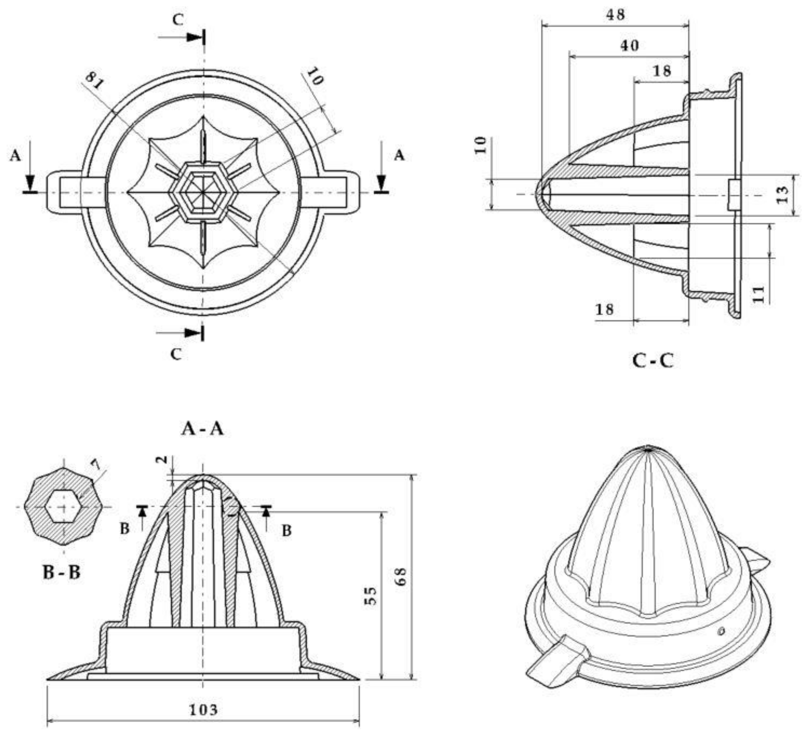
2.1. Geometrical Design and Analysis for the Plastic Parts Manufactured through the Injection Molding Process
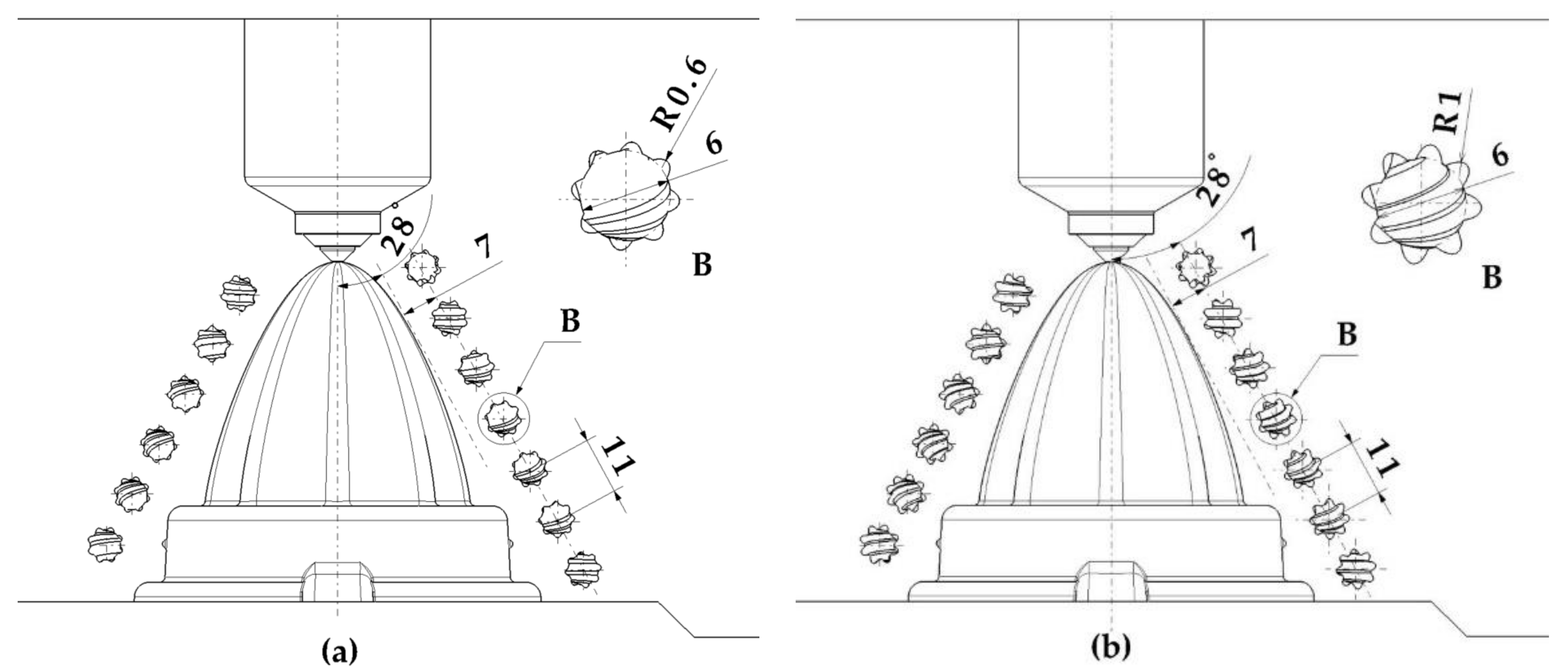
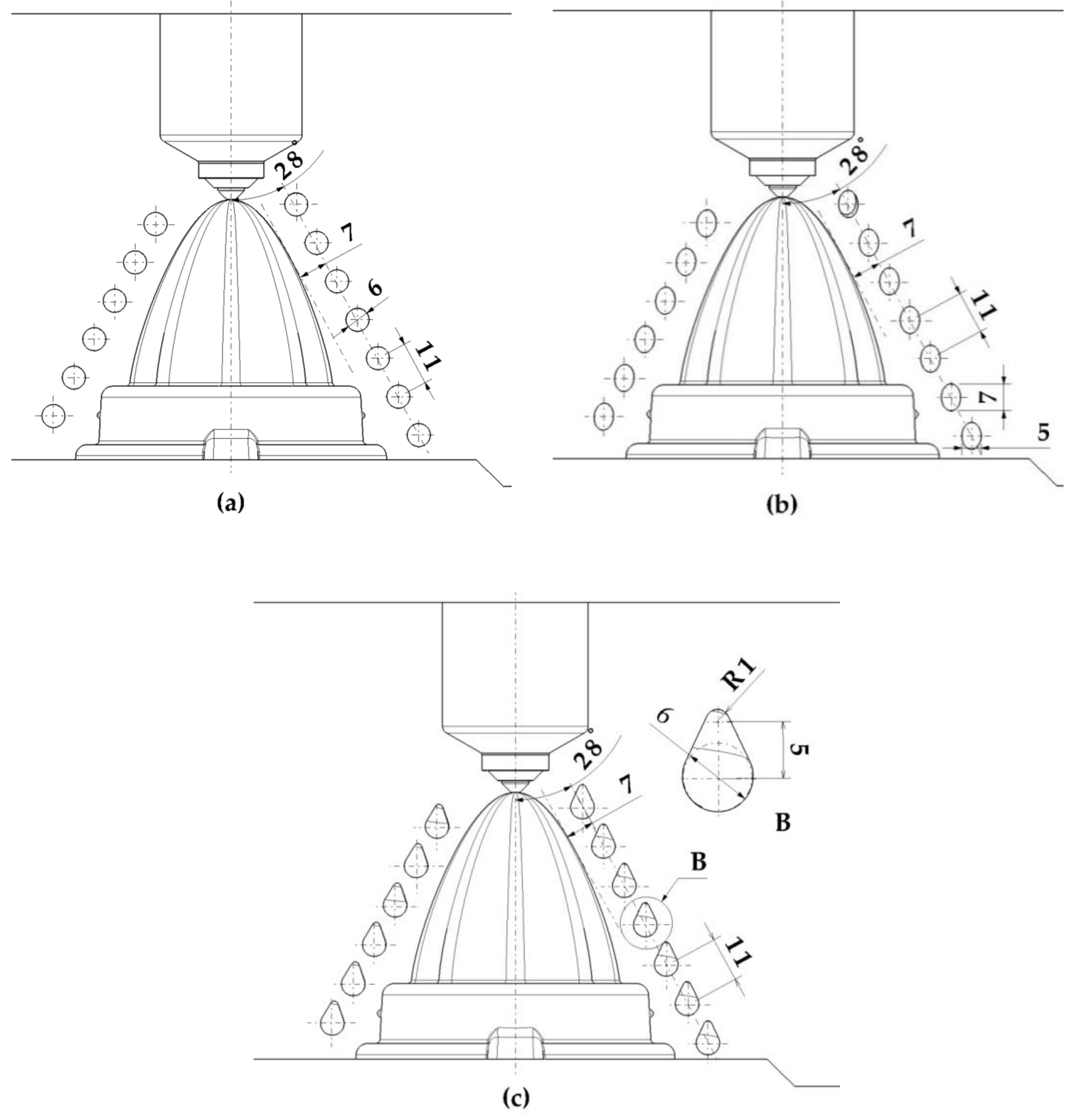
2.2. Green Conformal Cooling Channels Design
2.3. Materials
3. Implementation and Results
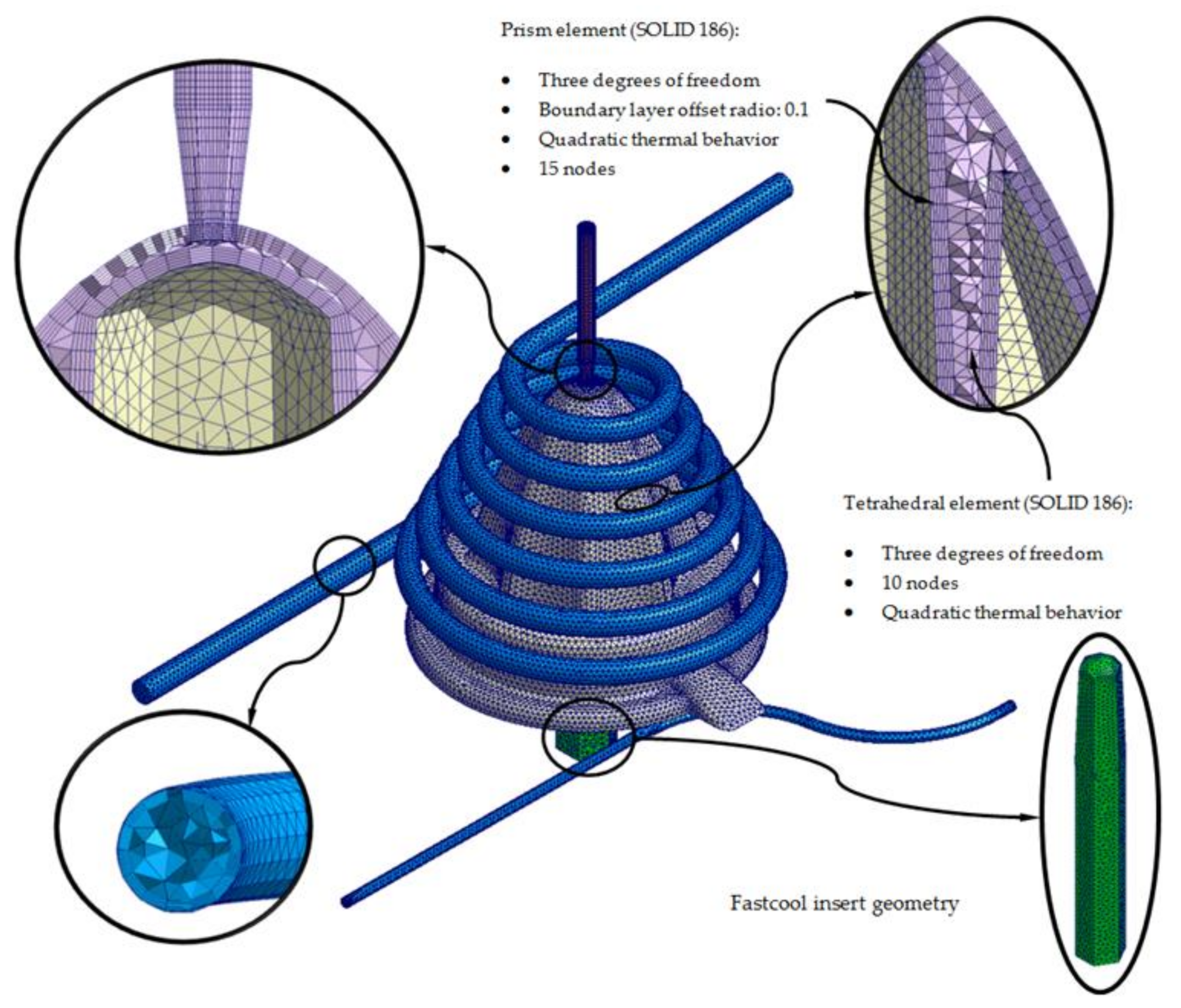
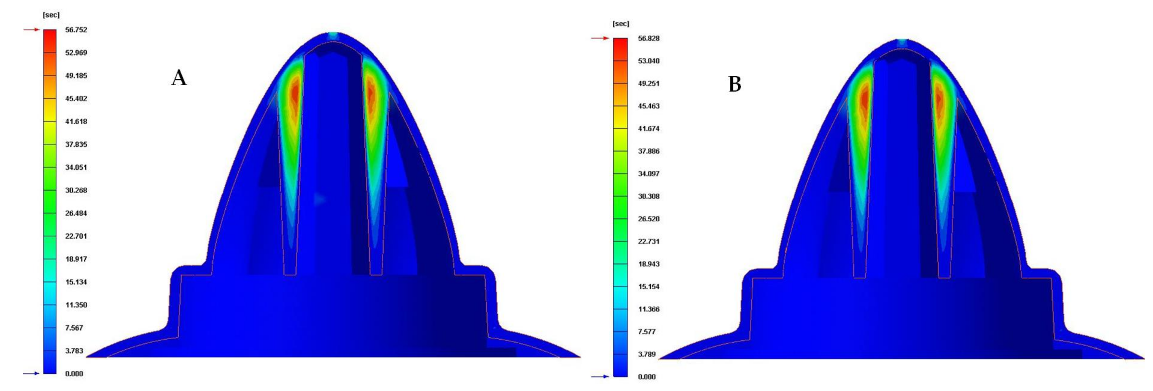
Modeling of Numerical Simulations for the Thermal Analysis of the Green Conformal Cooling System
- Since the complete cooling process of the plastic part is analyzed over time, the type of numerical analysis used is “Cooling transient”.
- The total cooling time established for each numerical analysis is 90 s, with a time step between each time step of 10 s. For each defined time step, the numerical analysis software stores the solution obtained. Therefore, in each numerical simulation carried out, the time until reaching the ejection temperature of the plastic part and the evolution of the temperature map throughout the cooling phase can be precisely determined.
- The analysis of the behavior and evolution of the physical, dynamic and thermal properties of the coolant flow along the channels of the cooling system was modeled according to the “Run 3D cooling channels” configuration.
- The methodology used to configure the solver, in the resolution of each numerical analysis carried out, is of the type maximum variation of mold temperature, whose magnitudes established for the parameter temperature difference and maximum cycle number are 1 and 10 °C, respectively.
- The turbulence model used for the development of the numerical analyses is established using the roughness parameter. This parameter defines the interface surface between the coolant flow and the surface of the cooling channels. The magnitude defined for this technological parameter is equal to 0.02 mm
4. Conclusions
Author Contributions
Funding
Institutional Review Board Statement
Informed Consent Statement
Data Availability Statement
Acknowledgments
Conflicts of Interest
References
- Doñate, C.M.; Paramio, M.R. New methodology for demoldability analysis based on volume discretization algorithms. Comput.-Aided Des. 2013, 45, 229–240. [Google Scholar] [CrossRef]
- Martin-Doñate, C.; Shaikheleid, S.; Torres-Alba, A.; Mercado-Colmenero, J.M. A New Smart Web Platform for Plastic Injection Molds in Industry 4.0 Environments. In Advances on Mechanics, Design Engineering and Manufacturing III; Springer: New York, NY, USA, 2021; pp. 309–315. [Google Scholar]
- Mercado-Colmenero, J.M.; Muriana, J.A.M.; Rubio-Paramio, M.A.; Martín-Doñate, C. An automated manufacturing analysis of plastic parts using faceted surfaces. In Advances on Mechanics, Design Engineering and Manufacturing; Springer: Berlin, Germany, 2016; pp. 119–128. [Google Scholar]
- Mercado-Colmenero, J.M.; Martin-Doñate, C.; Moramarco, V.; Attolico, M.A.; Renna, G.; Rodriguez-Santiago, M.; Casavola, C. Mechanical characterization of the plastic material GF-PA6 manufactured using FDM technology for a compression uniaxial stress field via an experimental and numerical analysis. Polymers 2020, 12, 246. [Google Scholar] [CrossRef] [PubMed] [Green Version]
- Mercado-Colmenero, J.M.; La Rubia, M.D.; Mata-Garcia, E.; Rodriguez-Santiago, M.; Martin-Doñate, C. Experimental and numerical analysis for the mechanical characterization of petg polymers manufactured with fdm technology under pure uniaxial compression stress states for architectural applications. Polymers 2020, 12, 2202. [Google Scholar] [CrossRef]
- Kuo, C.C.; Chen, W.H. Improving cooling performance of injection molding tool with conformal cooling channel by adding hybrid fillers. Polymers 2021, 13, 1224. [Google Scholar] [CrossRef]
- Jahan, S.A.; Wu, T.; Zhang, Y.; Zhang, J.; Tovar, A.; Elmounayri, H. Thermo-mechanical design optimization of conformal cooling channels using design of experiments approach. Procedia Manuf. 2017, 10, 898–911. [Google Scholar] [CrossRef]
- Zink, B.; Szabó, F.; Hatos, I.; Suplicz, A.; Kovács, N.K.; Hargitai, H.; Tábi, T.; Kovács, J.G. Enhanced injection molding simulation of advanced injection molds. Polymers 2017, 9, 77. [Google Scholar] [CrossRef] [Green Version]
- Tang, Y.; Gao, Z.; Zhao, Y.F. Design of Conformal Porous Structures for the Cooling System of an Injection Mold Fabricated by Additive Manufacturing Process. J. Mech. Des. 2019, 141, 101702. [Google Scholar] [CrossRef]
- Meekers, I.; Paul, R.; Arif, R. Analysis of Process Parameters affecting Energy Consumption in Plastic Injection Moulding. Procedia CIRP 2018, 69, 342–347. [Google Scholar] [CrossRef]
- Park, H.-S.; Dang, X.P. Development of a smart plastic injection mold with conformal cooling channels. Procedia Manuf. 2017. [Google Scholar] [CrossRef]
- Torres-Alba, A.; Diaz-Perete, D.; Mercado-Colmenero, J.M. Conformal Cooling Systems Design and Dimensioning for Injection Molds. In Advances in Design Engineering; Springer Nature: Logroño, Spain, 2019; pp. 166–174. [Google Scholar]
- Torres-Alba, A.; Mercado-Colmenero, J.M.; Diaz-Perete, D.; Martin-Doñate, C. A new conformal cooling design procedure for injection molding based on temperature clusters and multidimensional discrete models. Polymers 2020, 12, 154. [Google Scholar] [CrossRef] [Green Version]
- Wang, Y.; Yu, K.M.; Wang, C.C.; Zhang, Y. Automatic design of conformal cooling circuits for rapid tooling. Comput.-Aided Des. 2011, 43, 1001–1010. [Google Scholar] [CrossRef]
- Berger, G.R.; Zorn, D.; Friesenbichler, W.; Bevc, F.; Bodor, C.J. Efficient cooling of hot spots in injection molding. A biomimetic cooling channel versus a heat-conductive mold material and a heat conductive plastics. Polym. Eng. Sci. 2019, 59, E180–E188. [Google Scholar] [CrossRef] [Green Version]
- Choi, J.H.; Kim, J.S.; Han, E.S.; Park, H.P.; Rhee, B.O. Study on an optimized configuration of conformal cooling channel by branching law. In Engineering Systems Design and Analysis; ASME: New York, NY, USA, 2014; p. V001T06A007. [Google Scholar]
- Shinde, M.S.; Ashtankar, K.M.; Kuthe, A.M.; Dahake, S.W.; Mawale, M.B. Direct rapid manufacturing of molds with conformal cooling channels. Rapid Proto. J. 2018. [Google Scholar] [CrossRef]
- Saifullah, A.; Masood, S.H. Optimum cooling channels design and Thermal analysis of an Injection moulded plastic part mould. Mater. Sci. Forum 2007. [Google Scholar] [CrossRef]
- Wahab, M.S.; Raus, A.A.; Amir, I.; Ahmed, A.; Kamarudin, K. The thermal effect of variate cross-sectional profile on conformal cooling channels in plastic injection moulding. Int. J. Integr. Eng. 2018. [Google Scholar] [CrossRef]
- Rahim, S.Z.A.; Sharif, S.; Zain, A.M.; Nasir, S.M.; Mohd Saad, R. Improving the quality and productivity of molded parts with a new design of conformal cooling channels for the injection molding process. Adv. Polym. Tech. 2016. [Google Scholar] [CrossRef]
- Collomb, J.; Balland, P.; Francescato, P.; Gardet, Y.; Leh, D.; Saffré, P. Thermomechanical optimization and comparison of a low thermal inertia mold with rectangular heating channels and a conventional mold. Adv. Mater. Sci. Eng. 2019. [Google Scholar] [CrossRef] [Green Version]
- Kamat, A.M.; Pei, Y. An analytical method to predict and compensate for residual stress-induced warpage in overhanging regions of internal channels fabricated using powder bed fusion. Addit. Manuf. 2019. [Google Scholar] [CrossRef]
- Sharma, S.G.; Singraur, D.S.; Sudhakar, D.S.S. Transient analysis of an injection mould with conformal cooling channels. In Recent Advances in Mechanical Infrastructure; Springer: Berlin, Germany, 2020; pp. 235–244. [Google Scholar]
- Altaf, K.; Raghavan, V.R.; Rani, A.M.A. Comparative thermal analysis of circular and profiled cooling channels for injection mold tools. J. Appl. Sci. 2011, 11, 2068–2071. [Google Scholar] [CrossRef] [Green Version]
- Xi, L.; Gao, J.; Xu, L.; Zhao, Z.; Li, Y. Study on heat transfer performance of steam-cooled ribbed channel using neural networks and genetic algorithms. Int. J. Heat Mass Transfer 2018, 127, 1110–1123. [Google Scholar] [CrossRef]
- Wang, W.; Zhang, Y.; Li, Y.; Han, H.; Li, B. Numerical study on fully-developed turbulent flow and heat transfer in inward corrugated tubes with double-objective optimization. Int. J. Heat Mass Transfer 2018, 120, 782–792. [Google Scholar] [CrossRef]
- Jiang, G.; Gao, J.; Shi, X.; Li, F.; Xu, L. Flow and heat transfer characteristics of the mist/steam two-phase flow cooling the rectangular channel with column-row-ribs. Int. J. Heat Mass Transfer 2020, 156, 119737. [Google Scholar] [CrossRef]
- Freitas, P.; Santos, C.; Carreira, P.; Mateus, A. High efficiency cooling and heating channels for injection moulding. Appl. Mech. Mater. 2019. [Google Scholar] [CrossRef] [Green Version]
- Sachs, E.; Wylonis, E.; Allen, S.; Cima, M.; Guo, H. Production of injection molding tooling with conformal cooling channels using the three dimensional printing process. Polym. Eng. Sci. 2000, 40, 1232–1247. [Google Scholar] [CrossRef] [Green Version]
- Menges, G.; Michaeli, W.; Mohren, P. How to Make Injection Molds; Hanser Publishers: Cincinnati, OH, USA, 2001; pp. 1–612. [Google Scholar]
- Zhong, Z.W.; Leong, M.H.; Liu, X.D. The wear rates and performance of three mold insert materials. Mater. Des. 2011, 32, 643–648. [Google Scholar] [CrossRef]
- Valls, I.; Hamasaiid, A.; Padré, A. High thermal conductivity and high wear resistance tool steels for cost-effective hot stamping tools. J. Phys. Conf. Ser. 2017. [Google Scholar] [CrossRef] [Green Version]
- Mercado-Colmenero, J.M.; Rubio-Paramio, M.A.; Karlinger, P.; Martin-Doñate, C. A new procedure for calculating cycle time in injection molding based on plastic part geometry recognition. Int. J. Adv. Manuf. Technol. 2018, 98, 441–477. [Google Scholar] [CrossRef]
- Mercado-Colmenero, J.M.; Rubio-Paramio, M.A.; de Juanes Marquez-Sevillano, J.; Martin-Doñate, C. A new method for the automated design of cooling systems in injection molds. Comput.-Aided Des. 2018, 104, 60–86. [Google Scholar] [CrossRef]
- Vasco, J.; Barreiros, F.M.; Nabais, A.; Reis, N. Additive manufacturing applied to injection moulding: Technical and economic impact. Rapid Proto. J. 2019. [Google Scholar] [CrossRef]
- Torres-Alba, A.; Mercado-Colmenero, J.M.; Caballero-Garcia, J.d.D.; Martin-Doñate, C. Application of New Triple Hook-Shaped Conformal Cooling Channels for Cores and Sliders in Injection Molding to Reduce Residual Stress and Warping in Complex Plastic Optical Parts. Polymers 2021, 13, 2944. [Google Scholar] [CrossRef]
- Park, H.S.; Dang, X.P.; Song, X.P. Improving the Cooling Efficiency for the Molding of a Complex Automotive Plastic Part by 3D Printing Technology. Trans. Korean Soc. Automot. 2017, 25, 508–515. [Google Scholar] [CrossRef]
- Park, H.S.; Dang, X.P.; Nguyen, D.S.; Kumar, S. Design of advanced injection mold to increase cooling efficiency. Int. J. Precis. Eng. Manuf.-Green Technol. 2020, 7, 319–328. [Google Scholar] [CrossRef]
- Ahn, D.G.; Park, S.H.; Kim, H.S. Manufacture of an injection mould with rapid and uniform cooling characteristics for the fan parts using a DMT process. Int. J. Precis. Eng. Manuf.-Green Technol. 2010, 11, 915–924. [Google Scholar] [CrossRef]
- Cycle Time Reduction in Injection Moulding with Conformal Cooling Channels. Available online: https://researchbank.swinburne.edu.au/file/b9d88f55-8e50-4071-8265-498ccb3e3d45/1/PDF%20%28Published%20version%29.pdf (accessed on 10 August 2021).
- Saifullah, A.B.M.; Masood, S.H.; Sbarski, I. Thermal–structural analysis of bi-metallic conformal cooling for injection moulds. Int. J. Adv. Manuf. Technol. 2012, 62, 123–133. [Google Scholar] [CrossRef]
- Xu, X.; Sachs, E.; Allen, S. The design of conformal cooling channels in injection molding tooling. Polym. Eng. Sci. 2001, 41, 1265–1279. [Google Scholar] [CrossRef]
- Mercado-Colmenero, J.M.; Torres-Alba, A.; Catalan-Requena, J.; Martin-Doñate, C. A New Conformal Cooling System for Plastic Collimators Based on the Use of Complex Geometries and Optimization of Temperature Profiles. Polymers 2021, 13, 2744. [Google Scholar] [CrossRef] [PubMed]
- Mercado-Colmenero, J.M.; Martin-Doñate, C.; Rodriguez-Santiago, M.; Moral-Pulido, F.; Rubio-Paramio, M.A. A new conformal cooling lattice design procedure for injection molding applications based on expert algorithms. Int. J. Adv. Manuf. Technol. 2019, 102, 1719–1746. [Google Scholar] [CrossRef]
- Brooks, H.; Brigden, K. Design of conformal cooling layers with self-supporting lattices for additively manufactured tooling. Addit. Manuf. 2016, 11, 16–22. [Google Scholar] [CrossRef] [Green Version]
- Optimised Mould Temperature Control Procedure Using DMLS. Available online: https://www.3dimpuls.com/sites/default/files/download/eos_optimizedmouldtemperaturecontrolprocedureusing_dmls.pdf (accessed on 12 August 2021).
- Dassault Systemes. Available online: https://www.3ds.com/es/productos-y-servicios/catia/ (accessed on 1 September 2021).
- Moldex3d. Available online: https://www.moldex3d.com/ (accessed on 1 September 2021).


| Nomenclature | Units | Circular | Elliptical | Water Drop | Fluted Circular 1 mm | Fluted Circular 0.6 mm |
|---|---|---|---|---|---|---|
| As | mm2 | 28.27 | 27.49 | 35.93 | 39.27 | 39.27 |
| P | mm | 18.84 | 18.98 | 22.77 | 30.25 | 27.76 |
| Dh | mm | 6 | 5.79 | 6.31 | 5.19 | 5.66 |
| s | mm | 7 | 7 | 7 | 7 | 7 |
| p | mm | 11 | 11 | 11 | 11 | 11 |
| Nomenclature | Units | Description | Circular |
|---|---|---|---|
| As | mm2 | Section area | 4.9 |
| P | mm | Perimeter | 7.85 |
| Dh | mm | Hydraulic diameter | 2.5 |
| s | mm | Distance channel center—mold surface | 7 |
| p | mm | Pitch between channels | 7 |
| Nomenclature | Units | Description | PP 108MF10 |
|---|---|---|---|
| ρp | Kg/m3 | Density | 905 |
| Cp | J/Kg·°C | Specific heat | 2704 |
| δp | W/m·°C | Thermal conductivity coefficient | 0.1998 |
| Tmelt | °C | Melt temperature (normal) | 230 |
| Tmold | °C | Mold temperature (normal) | 40 |
| Teject | °C | Ejection temperature | 100 |
| Description | Units | Fastcool-50 |
|---|---|---|
| Density | g/cm3 | 7.81 |
| Yield strength 0,2% | MPa | 1070 |
| Mechanical resistance | MPa | 1400 |
| Elongation | % | 17 |
| Specific heat capacity | J/g·K | 0.47 |
| Thermal diffusivity | mm2/s | 13.5 |
| Thermal conductivity | (W/m·K) | 50 |
| Description | Units | Steel Alloy 1.2709 |
|---|---|---|
| Density | g/cm3 | 8000 |
| Specific heat capacity | J/g·K | 450 |
| Thermal conductivity coefficient | (W/m·K) | 20 |
| Description | Units | Value |
|---|---|---|
| Part mesh node count | - | 107,872 |
| Part mesh element count | - | 236,119 |
| Part mesh volume | cm3 | 33.89 |
| Runner mesh node count | - | 14,701 |
| Runner mesh element count | - | 13,440 |
| Runner mesh volume | cm3 | 0.5 |
| Plastic part precision (ε)—Mesh sizing | mm | 1.5 |
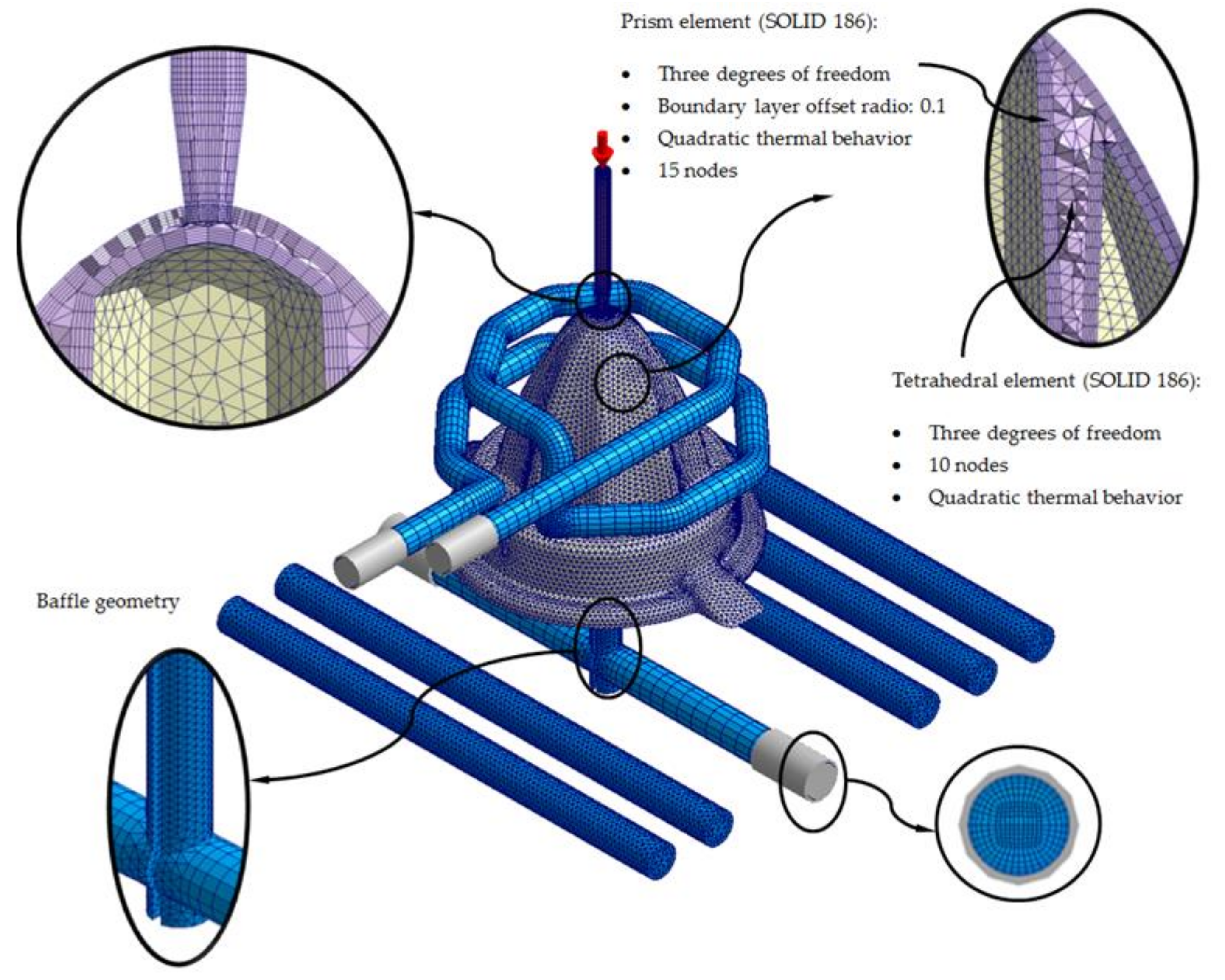
| Element type | - | Tetrahedral (10 nodes) |
| Element type—Boundary layers | - | Prism (15 nodes) |
| Offset ratio—Boundary layers | - | 0.1 |
| Description | Units | Study Cases—PP 108MF10 (PP) |
|---|---|---|
| Filling time | s | 1.19 |
| Packing time | s | 5.91 |
| Cooling time | s | 90 |
| Melt temperature | °C | 230 |
| Mold temperature | °C | 40 |
| Ejection temperature | °C | 100 |
| Coolant temperature | °C | 40 |
| Maximum injection pressure | MPa | 140 |
| Packing pressure profile | MPa | 85 (0.0–3.5 s) 40 (3.5–4.7 s) 10 (4.7–5.9 s) |
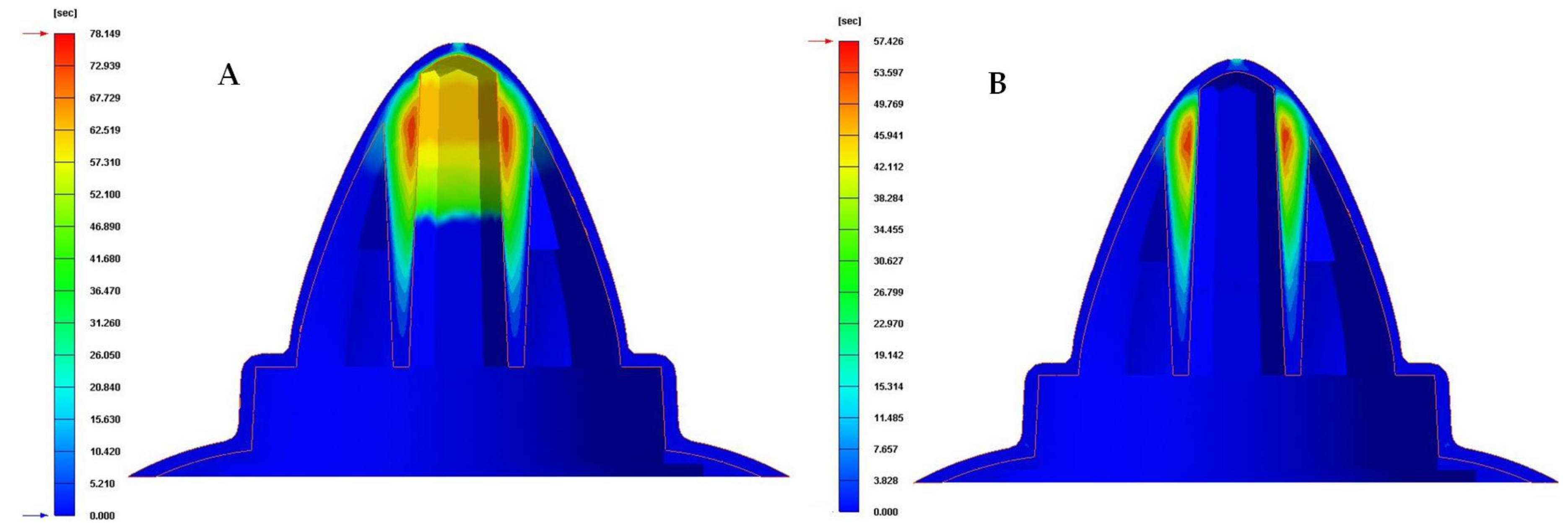
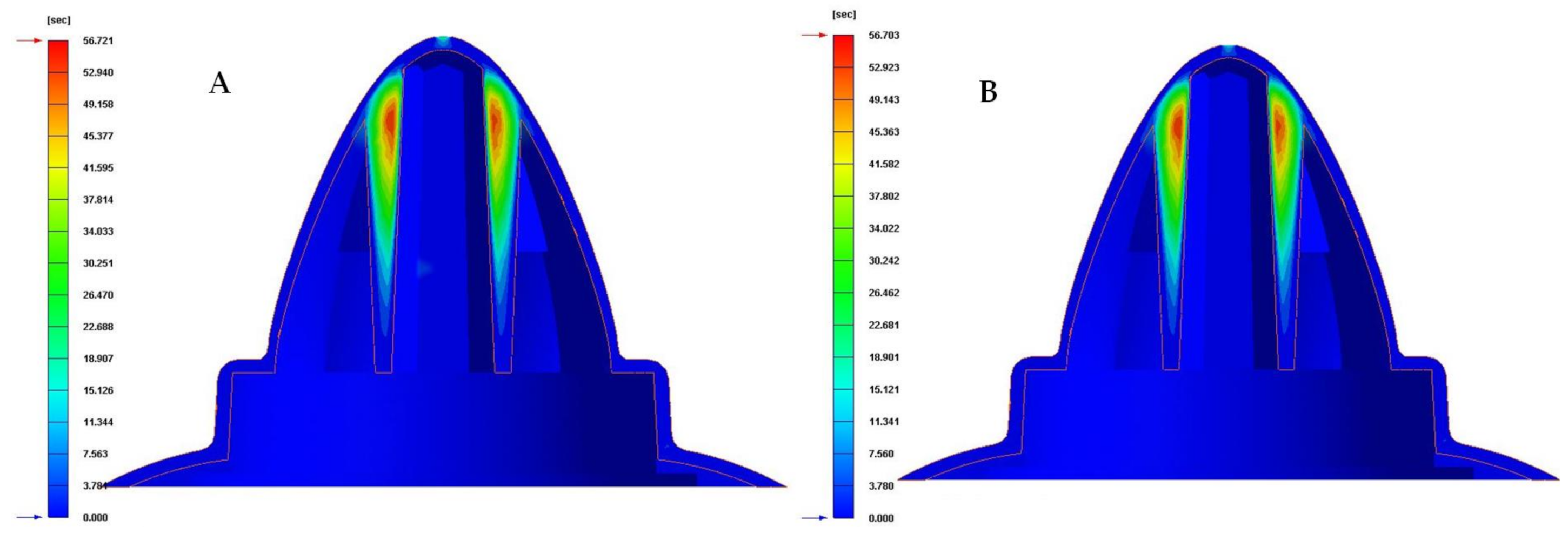
| Cooling System Configurations | Time to Each Ejection Temperature [s] | Time Reduction [s] | Performance Improvement [%] |
|---|---|---|---|
| Traditional | 78.149 | - | - |
| Circular | 57.426 | 20.723 | 26.5 |
| Water drop | 56.826 | 21.323 | 27.3 |
| Elliptical | 56.752 | 21.397 | 27.4 |
| Fluted 0.6 mm | 56.721 | 21.428 | 27.4 |
| Fluted 1 mm | 56.703 | 21.446 | 27.4 |
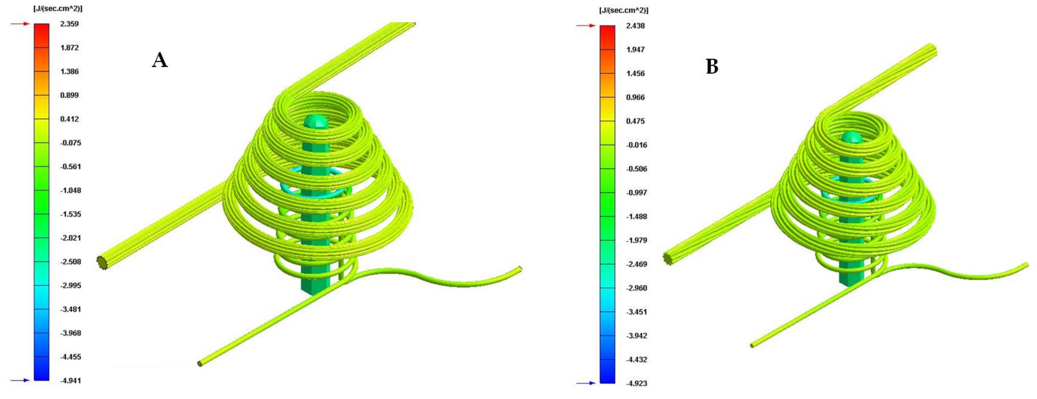
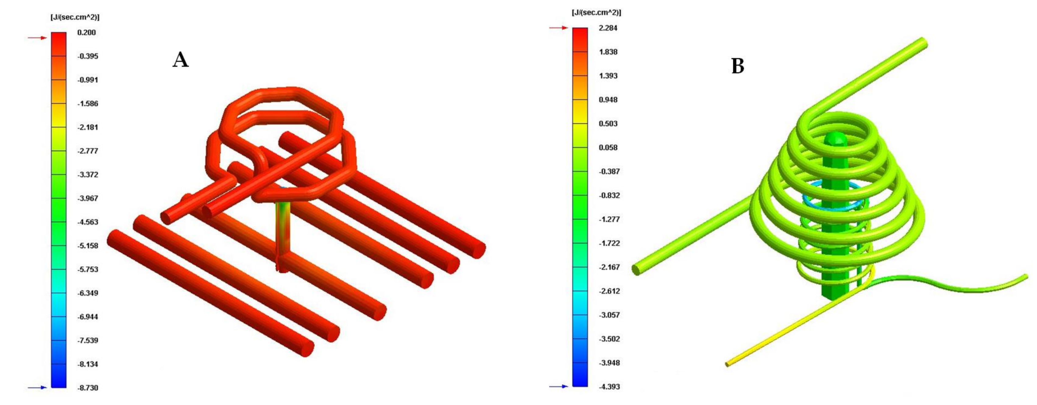
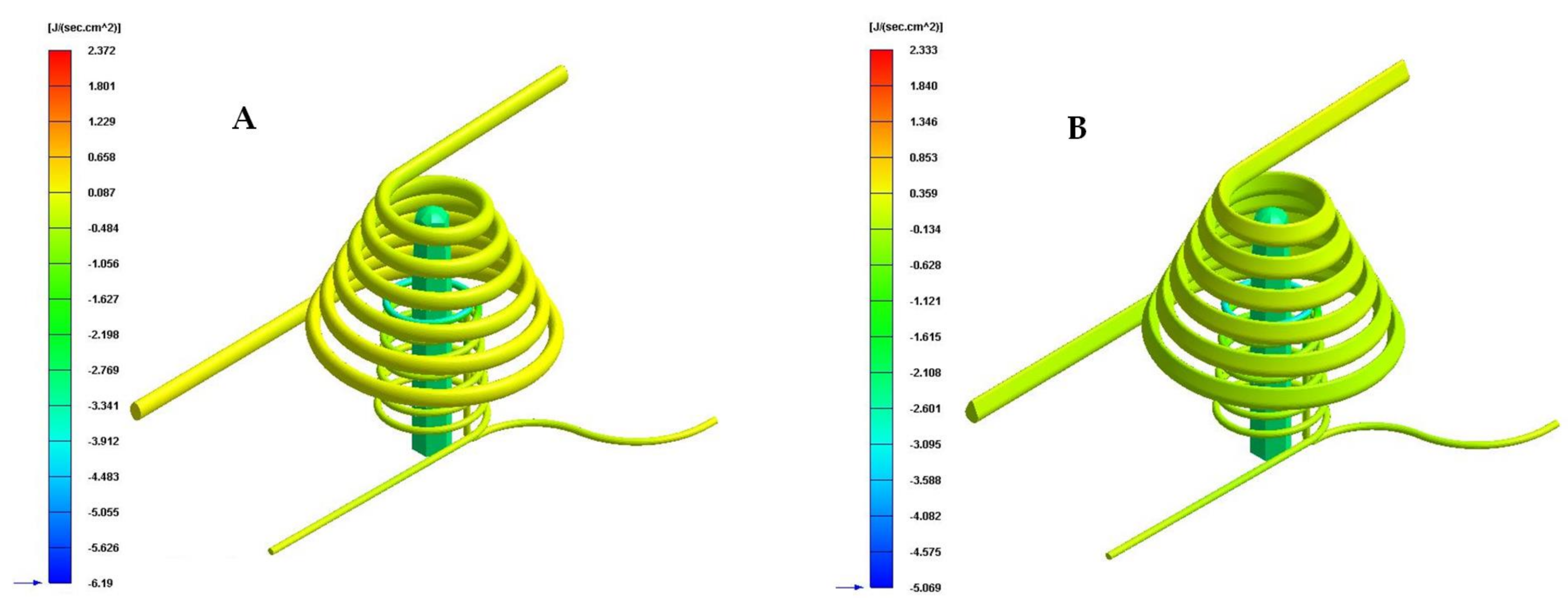
| Cooling System Configurations | Cavity Cooling [J/s·cm2] | Core Cooling [J/s·cm2] | Fastcool Insert [J/s·cm2] | Total [J/s·cm2] | Total Improvement [J/s·cm2] | Performance Improvement [%] |
|---|---|---|---|---|---|---|
| Traditional | 0.004 | 0.059 | - | 0.063 | - | - |
| Circular | 0.046 | 0.078 | 2.284 | 2.408 | 2.471 | 3722 |
| Raindrop | 0.195 | 0.085 | 2.333 | 2.613 | 2.550 | 4048 |
| Elliptical | 0.268 | 0.017 | 2.372 | 2.657 | 2.594 | 4118 |
| Fluted 0.6 mm | 0.206 | 0.103 | 2.359 | 2.668 | 2.605 | 4135 |
| Fluted 1 mm | 0.238 | 0.118 | 2.438 | 2.794 | 2.731 | 4335 |
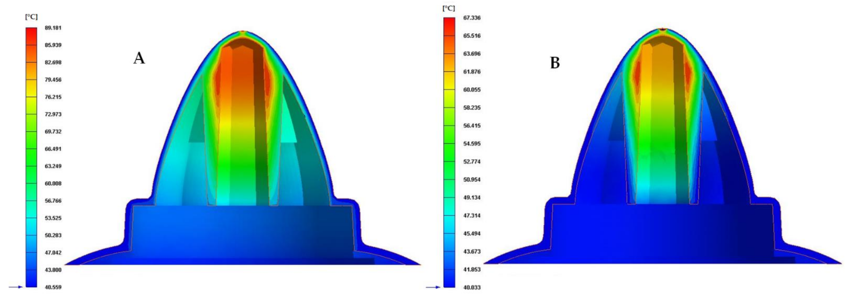
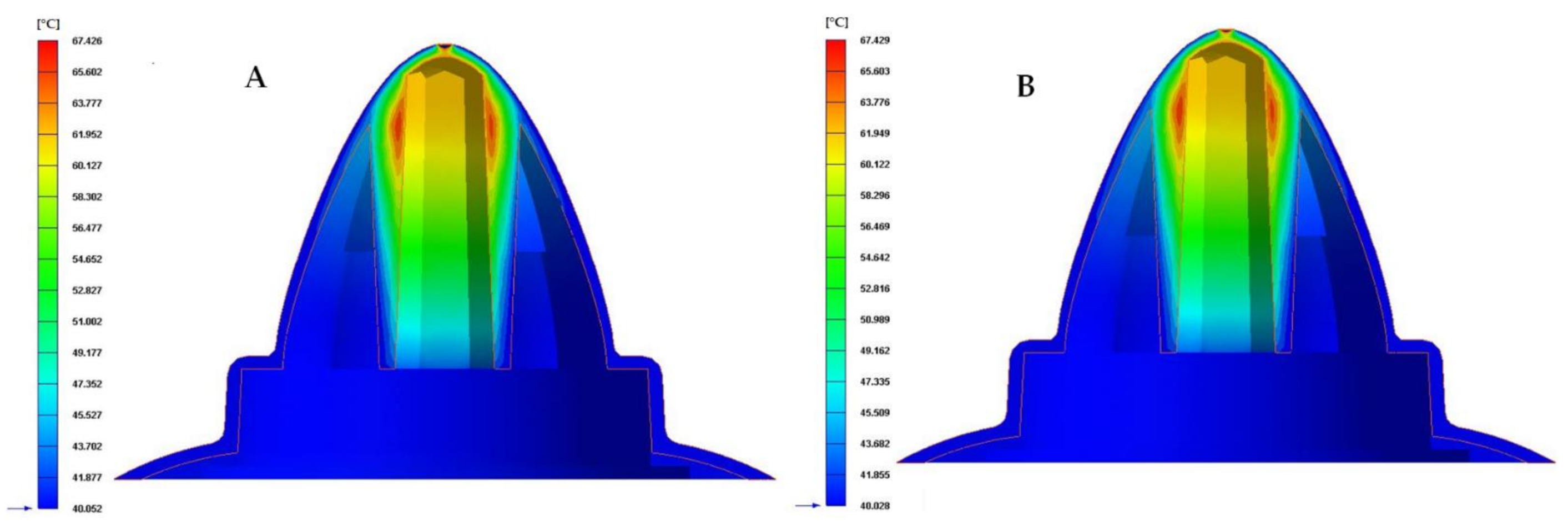
| Cooling System Configurations | Mold Temperature Difference [°C] | Total Improvement [°C] | Performance Improvement [%] |
|---|---|---|---|
| Traditional | 44.728 | - | - |
| Circular | 22.635 | 22.093 | 49.4 |
| Water drop | 22.432 | 22.296 | 49.8 |
| Elliptical | 22.450 | 22.278 | 49.8 |
| Fluted 0.6 mm | 21.644 | 23.084 | 51.6 |
| Fluted 1 mm | 21.619 | 23.109 | 51.7 |
Publisher’s Note: MDPI stays neutral with regard to jurisdictional claims in published maps and institutional affiliations. |
© 2021 by the authors. Licensee MDPI, Basel, Switzerland. This article is an open access article distributed under the terms and conditions of the Creative Commons Attribution (CC BY) license (https://creativecommons.org/licenses/by/4.0/).
Share and Cite
Torres-Alba, A.; Mercado-Colmenero, J.M.; Caballero-Garcia, J.D.D.; Martin-Doñate, C. A Hybrid Cooling Model Based on the Use of Newly Designed Fluted Conformal Cooling Channels and Fastcool Inserts for Green Molds. Polymers 2021, 13, 3115. https://doi.org/10.3390/polym13183115
Torres-Alba A, Mercado-Colmenero JM, Caballero-Garcia JDD, Martin-Doñate C. A Hybrid Cooling Model Based on the Use of Newly Designed Fluted Conformal Cooling Channels and Fastcool Inserts for Green Molds. Polymers. 2021; 13(18):3115. https://doi.org/10.3390/polym13183115
Chicago/Turabian StyleTorres-Alba, Abelardo, Jorge Manuel Mercado-Colmenero, Juan De Dios Caballero-Garcia, and Cristina Martin-Doñate. 2021. "A Hybrid Cooling Model Based on the Use of Newly Designed Fluted Conformal Cooling Channels and Fastcool Inserts for Green Molds" Polymers 13, no. 18: 3115. https://doi.org/10.3390/polym13183115
APA StyleTorres-Alba, A., Mercado-Colmenero, J. M., Caballero-Garcia, J. D. D., & Martin-Doñate, C. (2021). A Hybrid Cooling Model Based on the Use of Newly Designed Fluted Conformal Cooling Channels and Fastcool Inserts for Green Molds. Polymers, 13(18), 3115. https://doi.org/10.3390/polym13183115