Article

Non-Uniform Curvature Model and Numerical Simulation for Anti-Symmetric Cylindrical Bistable Polymer Composite Shells

Key Laboratory of E&M, Zhejiang University of Technology, Ministry of Education & Zhejiang Province, Hangzhou 310014, China
*
Author to whom correspondence should be addressed.
Polymers 2020, 12(5), 1001; https://doi.org/10.3390/polym12051001
Submission received: 2 April 2020 / Revised: 21 April 2020 / Accepted: 23 April 2020 / Published: 26 April 2020
(This article belongs to the Section Polymer Physics and Theory)

Abstract

:
The bistability of anti-symmetric thin shallow cylindrical polymer composite shells, made of carbon fiber/epoxy resin, has already been investigated based on the uniform curvature and inextensible deformation assumptions by researchers in detail. In this paper, a non-uniform curvature model that considers the extensible deformations is proposed. Furthermore, a parametric modeling and automatic postprocessing plug-in component for the bistability analysis of polymer composite cylindrical shells is established by means of ABAQUS-software, by which the equilibrium configurations and the load-displacement curves during the snap process can be easily obtained. The presented analytical model is validated by the numerical simulation and literature models, while the factors affecting the bistability of anti-symmetric cylindrical shells are revisited. In addition, the planform effects of anti-symmetric cylindrical shells with rectangular, elliptical and trapezoidal planform are discussed. The results show that the presented analytical model improves the accuracy of the prediction of the principal curvature of second equilibrium configuration and agree well with the numerical results.

Graphical Abstract

1. Introduction

Owing to the ability to provide stiffness and strength during large shape change, bistable thin shallow polymer composite structures have shown potential as morphing structures used in aerospace [1,2,3], origami [4,5] and bionics [6,7,8]. Such morphing structure can also find applications in vibration energy harvest systems [9,10] and gearless motors [11], as well as anti-icing systems [12]. The bistability may stem from the pre-stress or plastic deformations [13,14,15,16], the inducing stresses through thermal effects for non-symmetric layup [17,18,19], or the combined influence of the material properties and geometry [20,21,22]. Since the equilibrium configurations can be quite different under various manufacturing methods, it demands that the analytical model and finite-element analysis are able to predict the bistability.
In this paper, we focus on the anti-symmetric cylindrical shells that are made of carbon-fiber/epoxy resin composites. Based on the assumption of uniform curvature and the classical laminate theory (CLT), some simplified models [23,24,25,26] have been proposed assuming the inextensible deformation, which implies that the second equilibrium configuration remained as a standard cylinder. A two-parameter inextensional uniform curvature model (IUCM) used to analyze the bistability of cylindrical shells was summarized and proposed by Guest and Pellegrino [20]. On this basis, the factors affecting the bistability have been systematically investigated [27,28,29,30,31], showing a reasonable agreement among experimental, numerical and analytical results. However, the inextensible deformation assumption may lead to inconformity with the practical deformations. Thus, the accuracy of the analytical prediction deserves further consideration.
Considering the importance of initial Gaussian curvature [32], which further governs the relative variation between the stretching and bending strain energy densities, Seffen [21] put forward an extensible uniform curvature model (EUCM). It considered the practical deformations of shells instead of that in inextensible deformation assumption. The combined influence of the material properties and geometry was explored in a systematic way to reveal possible bistable solutions. On this basis, Vidoli and Maurini [22] extended the EUCM, and found the existence of three equilibrium configurations for a specific wide range of initial curvatures. Furthermore, the inelastic deformations pertinent to thermal, hygroscopic or plastic effects were summarized and introduced [33]. The multistability of shells was studied to provide the basic criteria for the design of multistable shells [34]. In addition, Vidoli [35] developed non-uniform curvature models that assumed curvature to vary linearly and quadratically, labeled as linearly varying curvature model (LCVM) and quadratically varying curvature model (QCVM), respectively. The bistability of unsymmetric plates was analyzed and the dependence of the average curvatures on the aspect ratio was correctly captured. The bistable equilibrium configurations of thin shallow shell with clamped boundary condition [36,37] were predicted as well. The uniform curvature assumption was also weakened [38,39] by using high-order approximations for displacement field on the basis of the Rayleigh–Ritz method and the discretization of Föppl–Von Kármán (FVK) equations [40]. Thus, complex nonlinear bistable behavior can be captured in detail by using high-order approximations and the non-uniform curvature assumption despite of a certain computational cost.
To the best of our knowledge, the bistability of anti-symmetric cylindrical polymer composite shells has not been reported based on the non-uniform curvature assumption. This paper adopts extensible deformation assumption and presents a non-uniform curvature model (NUCM), assuming curvatures to vary quadratically as well, for more accurate predictions. The layout of this paper is as follows: in Section 2, the NUCM is proposed. The presented analytical model is verified by fully non-linear finite element analysis (FEA) using an ABAQUS plug-in component based on Python script. The specific plug-in component allowing for parameterized geometric modeling and automatically postprocessing in a systematic and efficient way is introduced in Section 3. Section 4 validates the accuracy of the presented model. In addition, the factors affecting the bistability of anti-symmetric cylindrical polymer composite shells are discussed, especially the planform effects of them. Section 5 draws the conclusions.

2. Analytical Model

The analytical model follows the similar reduction procedure of Vidoli [35]; however, several extensions have been incorporated. The main features of the presented model are briefly recalled. One can see Appendix A for more details.
The stable equilibrium configurations of an FVK shell can be found as local minima of the total energy. The shells’ boundaries are free without applied forces, and the total potential energy is expressed as [35]
U ¯ = 1 2 Ω [ D ¯ ( K H ) ( K H ) + 12 R 0 2 t z 2 A ¯ 1 Σ Σ ] d Ω
Equation (1) is a dimensionless form and the dimensionless quantities are as follows
X = x / L , Y = y / L , W = w / L , K = R 0 k ,   H = R 0 h A ¯ = A / A 11 , B ¯ = B / ( A 11 R 0 ) , D ¯ = D * / D 11 * , Σ = N / A 11 U ¯ = U R 0 2 / ( L 2 D 11 * )
where L2 is the area of the planform of the shell, R0 is a characteristics radius employed to scale the curvatures, N is the membranal stress, and w is the tranverse displacement. H represents the dimensionless initial curvature and describes the initial stress-free configuration. K represents the dimensionless curvature. A, B, D are 3 × 3 matrices representing the extensional stiffness, the extension-to-bending coupling, and the bending stiffness, respectively. Specifically, D* = DBTA−1B. Under the consideration of the homogeneous deformation of shell through the thickness, the equivalent thickness is given as t z = 12 D 11 * / A 11 .
Considering the orthotropic material, the dimensionless stiffnesses can be written as
A ¯ = [ 1 v a 0 v a β a 0 0 0 γ a ] , D ¯ = [ 1 v d 0 v d β d 0 0 0 γ d ] γ a = ρ a ( 1 v a 2 / β a ) , γ d = ρ d ( 1 v d 2 / β d )
where va measures in-plane Poisson effect, βa measures the ratio between the extensional stiffnesses in the coordinate directions, ρa is the shear modulus, vd measures the Poisson effect in bending, βd measures the ratio between the bending stiffnesses in the coordinate directions, and ρd is the torsional modulus.
Substitute the constitutive relation of orthotropic material into the Gaussian compatibility (Equation (A1), see Appendix A):
β a v a β a v a 2 2 Σ X Y 2 + 1 v a β a v a 2 2 Σ Y X 2 2 γ a 2 Σ X Y X Y = K x K y K x y 2 ( H x H y H x y 2 ) = Δ G
where ΔG is the difference in dimensionless Gaussian curvature between the actual and natural configurations. The Gaussian curvatures are determined by the dimensionless transverse displacement W. The uniform curvature assumption represents that the Gaussian curvature is constant. The quadratically varying curvature assumption is adopted in NUCM, representing the Gaussian curvature, which varies quadratically. Cylindrical shells with three different planform shapes are discussed, labeled as rectangular planform shells (RPS), elliptical planform shells (EPS) and trapezoidal planform shells (TPS), respectively (see Figure 1). The coordinates are chosen to be centered in the centroid of the planform. For an RPS, the lengths along the x- and y- directions are 2a and 2b, while for an EPS, the major and minor axes lengths are 2a and 2b. Moreover, the TPS can be obtained by tailoring the shell with rectangular planform, in which an additional parameter c is used. The transverse displacements for RPS and EPS are expressed, respectively, as
W = 1 2 s 1 X 2 + 1 2 s 2 Y 2 + s 3 X Y + s 4 X 2 ( X 2 1 2 r ) + s 5 Y 2 ( Y 2 r 2 )
W = 1 2 s 1 X 2 + 1 2 s 2 Y 2 + s 3 X Y + s 4 X 2 ( X 2 3 1 2 π r ) + s 5 Y 2 ( Y 2 3 r 2 π )
which satisfy the average curvatures over the shell to be constant. In fact, s1, s2, s3 control the average curvatures over the shell, whilst s4 and s5 control the quadratic variation of the curvature along the direction x and y, respectively. r represents the aspect ratio, namely r = b/a. Due to the difficulty in choosing a transverse displacement to satisfy the average curvatures over the shell to be constant, the transverse displacement for TPS is chosen to be the same as that for RPS.
By substituting the corresponding transverse displacements into Equation (4), ΔG and the stress fields Σ for each W can be written in a same form, given by
Δ G = S 1 + S 2 X 2 + S 3 Y 2 + S 4 X 2 Y 2 Σ = l 2 R 0 2 [ S 1 T 1 + S 2 T 2 + S 3 T 3 + S 4 T 4 ]
where the detail of Si, Ti (I = 1,2,3,4) can be seen in Appendix A.
Therefore, the stretching energy can be obtained by using Equation (7) and the total potential dimensionless energy is then given as
U ¯ = 1 2 Ω D ¯ ( K H ) ( K H ) d Ω + 1 2 i = 1 4 j = 1 4 S ¯ i j ψ i j
where S ¯ i j = S i S j , ψ i j = Ω A ¯ 1 T i : T j d Ω ( i , j = 1 , 2 , 3 , 4 ) . The scalar factor ψij measures the ratio between bending and stretching energy and is obtained based on FEniCS framework [41].
Based on the principle of virtual work and the theorem of minimization of the total potential energy, the first variation of the total energy should be zero [42]
f i = U ¯ / s i = 0 ( i = 1 , 2 , , 5 )
Thus, the unknown coefficient si can be obtained by solving Equation (9), by which the equilibrium configurations are determined. The average curvature over the shell is used to describe the second equilibrium configuration of anti-symmetric cylindrical shell. The stability of the equilibrium configurations can be assessed by examining positive definiteness of the Jacobian matrix [43]
J = f i s j , i , j = 1 , 2 , , 5
In the context of this work, the expressions for fi and J are computed symbolically via MATHMATICA software and are solved with the aid of the MATLAB programming.

3. Finite Element Analysis

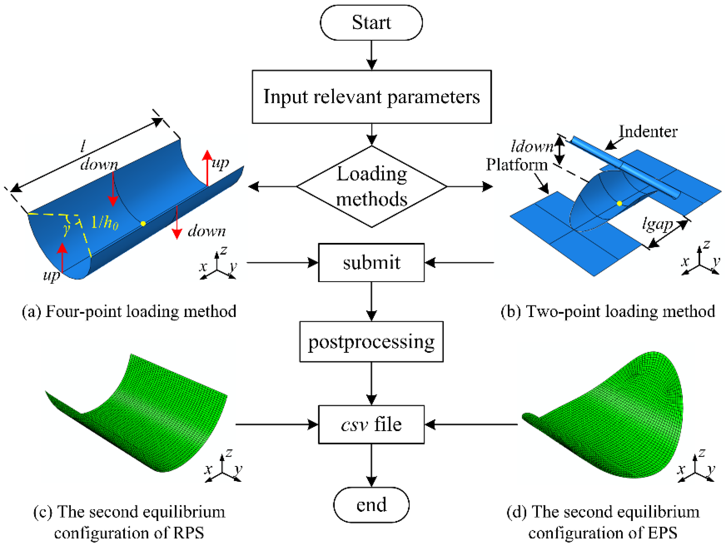
The bistability analysis of anti-symmetric cylindrical shells is validated by finite element simulation performed on ABAQUS software (version 6.14-1, Dassault Systemes Simulia Corp., Providence, RI, USA). Basically, the cylindrical shell can be characterized by the longitudinal length l, the angle of embrace γ, the initial curvature h0 and the planform shapes (see Figure 2a). The cylindrical shell with other planform shapes can be obtained by tailoring shell with rectangular planform. The material parameters used in the subsequent numerical simulations are listed in Table 1. The layup parameters consist of the layup angle and the thickness of a single layer t. The S4R shell element is chosen for a better convergence.
Two loading methods, the four-point loading method [44] and the two-point loading method [19], are adopted in numerical simulation to induce the snap-through and snap-back of anti-symmetric cylindrical shells. The four-point loading method is realized by imposing suitable displacements loads in four points at the shell edges intersecting the xz- and yz- planes and keeping the center of shell totally restrained, as indicated in Figure 2a, which has been used to predict the tristability of orthotropic doubly curved shell [44]. The two-point loading method is realized by moving the rigid indenter downward while keeping the two smooth supporting platforms fixed and the center of shell restrained, as shown in Figure 2b. It is an experimental method for the transformation of anti-symmetric cylindrical shell, which was also adopted in previous literature [27,28,29,30]. The load-displacement curves can be obtained by the indenter in finite element model in contrast to experimental results. Two steps are included in simulation: (1) the displacement loadings are applied with the option Nlgeom on and stabilization with dissipated energy fraction on with default values; (2) the displacement loadings are removed with the option Nlgeom on, and stabilize off to avoid inaccuracies. Thus, the cylindrical shell remains in a stress-free state with only the center of shell restrained, and will then transform to the second equilibrium configuration (see Figure 2c,d).
In the postprocessing, the curvatures are used to depict the equilibrium configurations, which are the average of the local curvatures for the whole elements. This conforms to the theoretical assumption. The load-displacement curves are obtained from a reference point of the indenter for the two-point loading method or two different loading points in the shell for the four-point loading method, thus the snap loads of the anti-symmetric cylindrical shells based on different loading method are obtained. Eventually, all of the above messages can be exported in a csv file for later usage.
The simulation procedure of the anti-symmetric cylindrical shells is summarized by using a Python script. Then, a parametric modeling plug-in is established based on the Python script to make the anti-symmetric cylindrical shell parametrically generated and the postprocessing automatically completed. The process of the plug-in is shown in Figure 2. The downward distance ldown and the gap between supporting platforms lgap in the two-point loading method and the downward and upward distance down and up in the four-point loading method can be adjusted for a better convergence. The default values are empirically set as: ldown = 1/h0 + 15 mm, lgap = 50 mm, based on the experimental observations, and down = 1/h0, up = 0.4l, based on the trial simulation.

4. Result and Discussion

In this section, results are presented with examples of an anti-symmetric cylindrical shell. The results from NUCM are compared with the results from FEA, IUCM, EUCM and QVCM. Unless otherwise stated, the geometric parameters of the anti-symmetric cylindrical shell are l = 120 mm, h0 = 0.04 mm−1, γ = 180°, t = 0.12 mm with a rectangular planform and the layup is [45°/−45°/45°/−45°].

4.1. Validation of Accuracy

The comparison results are demonstrated in Table 2, where kx2, ky2 represent the average curvatures in second equilibrium configuration of anti-symmetric cylindrical shells.
Compared with the QVCM with two degrees of freedom, the NUCM has five degrees of freedom, leading to the increase in computational cost and the complexity of the expression. But a large deviation is observed in Table 2 for QVCM against the numerical results. The same results are observed in many other examples that are therefore omitted here for brevity. It can be concluded that the QVCM, satisfying the bending boundary conditions on average, is not suitable to predict the bistability of an anti-symmetric cylindrical shell and will not be discussed later. In contrast, the results from EUCM and NUCM have a good agreement with the numerical results. In addition, compared to the results from EUCM, significant improvement in the accuracy of the average curvature is observed. The relative errors of the principal curvature kx2 are 1.04%, 10.11% and 11.15%, respectively, for NUCM, EUCM and IUCM. A remarkable improvement in accuracy is also observed for the curvature ky2. However, it is less important than the principal curvature kx2 and is neglected in the following discussion.

4.2. Factors Affecting the Bistability

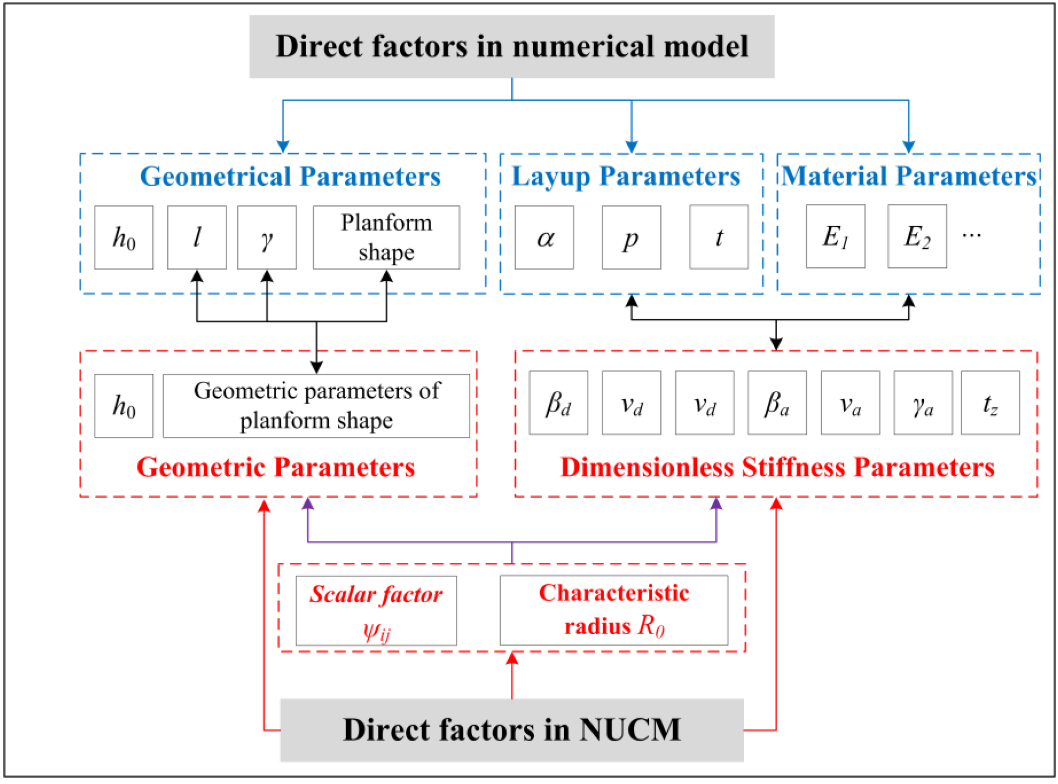
The factors affecting the bistable behavior of anti-symmetric cylindrical shells are investigated by the NUCM and FE simulation. The results from EUCM and IUCM are also given for a direct comparison. The bistable performances of anti-symmetric cylindrical shells are mainly affected by: (i) layup parameters containing angle of layup α, number of plies p, (ii) geometrical parameters including the angle of embrace γ, the longitudinal length l, the initial nature curvature h0 and planform shapes. Some factors have been studied in the previous literature [28], but a few extra considerations are reported with the NUCM. In essence, these factors directly influence the bistability of an anti-symmetric cylindrical shell in numerical model, but yet some of which do not affect straightforwardly in the NUCM. The direct factors for the bistability of anti-symmetric cylindrical shell in NUCM are: (i) the geometrical parameters used to describe the planform shape with the initial nature curvature, (ii) the dimensionless stiffness parameters, (3) the scalar factor ψij and characteristic radius R0 related to the dimensional transformation, both of which are affected by the former two factors. The relationships of the direct factors between the numerical simulation and NUCM are shown in the Figure 3. The geometric parameters relationship between them are: a = l/2, b = sin(γ/2)/h0, in which γ cannot exceed 180 degrees due to the duplication of b. Three examples are selected, referred to as No.1, No.2 and No.3, respectively. No.1 represents the classical anti-symmetric cylindrical shell as stated before. No.2 and No.3 are the same as No.1 except for a change in layup parameters (replaced with p = 5) or geometric parameters (replaced with a = 21.56 mm), respectively.

4.2.1. Influence of Scalar Factor and Characteristic Radius

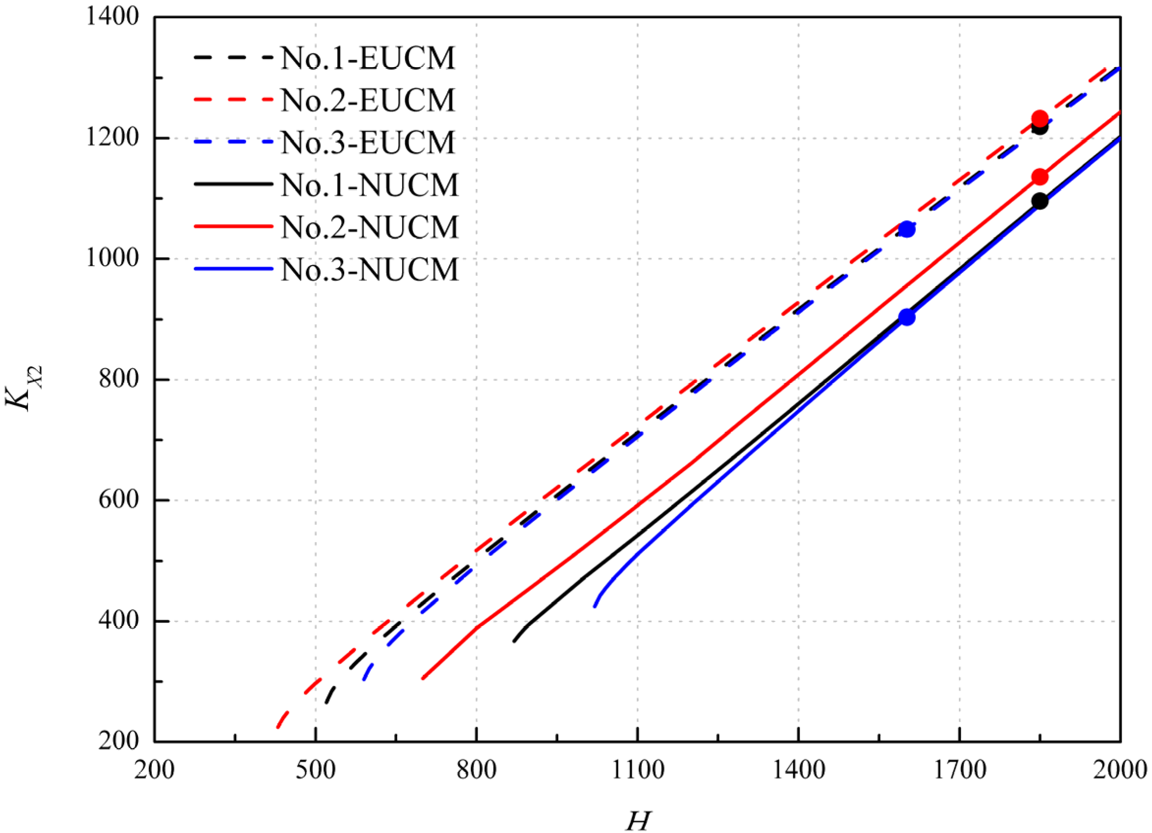
The scalar factor ψij is influenced by the layup parameters, material parameters and the geometrical parameters except for the initial curvature. When the scalar factor is determined, the bistability of anti-symmetric cylindrical shells can be investigated with the variation of dimensionless curvatures of the natural stress-free configuration (the initial twist curvature is assumed to be zero), (see bistability curves in Figure 4). When the characteristic radius R0 is determined, the principal curvature kx2 can be determined through dimensional transformation, corresponding to a point, i.e., the black dot shown in the Figure 4. All the bistability curves show similar trends with the different critical value, which relates to the vanishing of bistability. The scalar factor changed by geometrical parameters shows a slightly deviation for the trend and the initial dimensionless curvature H, but an obvious difference in the dimensionless curvature KX2. It is contrary to the scalar factor changed by layup parameters. In addition, the bistability curves of NUCM tend to be lower than that of EUCM, and the critical value is greater, which conforms to the trend shown in the Figure 9 in Ref. [35]. The bistability of anti-symmetric cylindrical shells exists when the point is on the curve, and disappears when the point deviates from the curve. Note that the corresponding point and the bistability curve vary for different cases. In this sense, the bistability range predicted by NUCM is narrower than that by EUCM. It can be concluded that the scalar factor ψij and characteristic radius R0 are the most important direct factors in the NUCM affecting the bistability of anti-symmetric cylindrical shells.

4.2.2. Influence of Layup Parameters

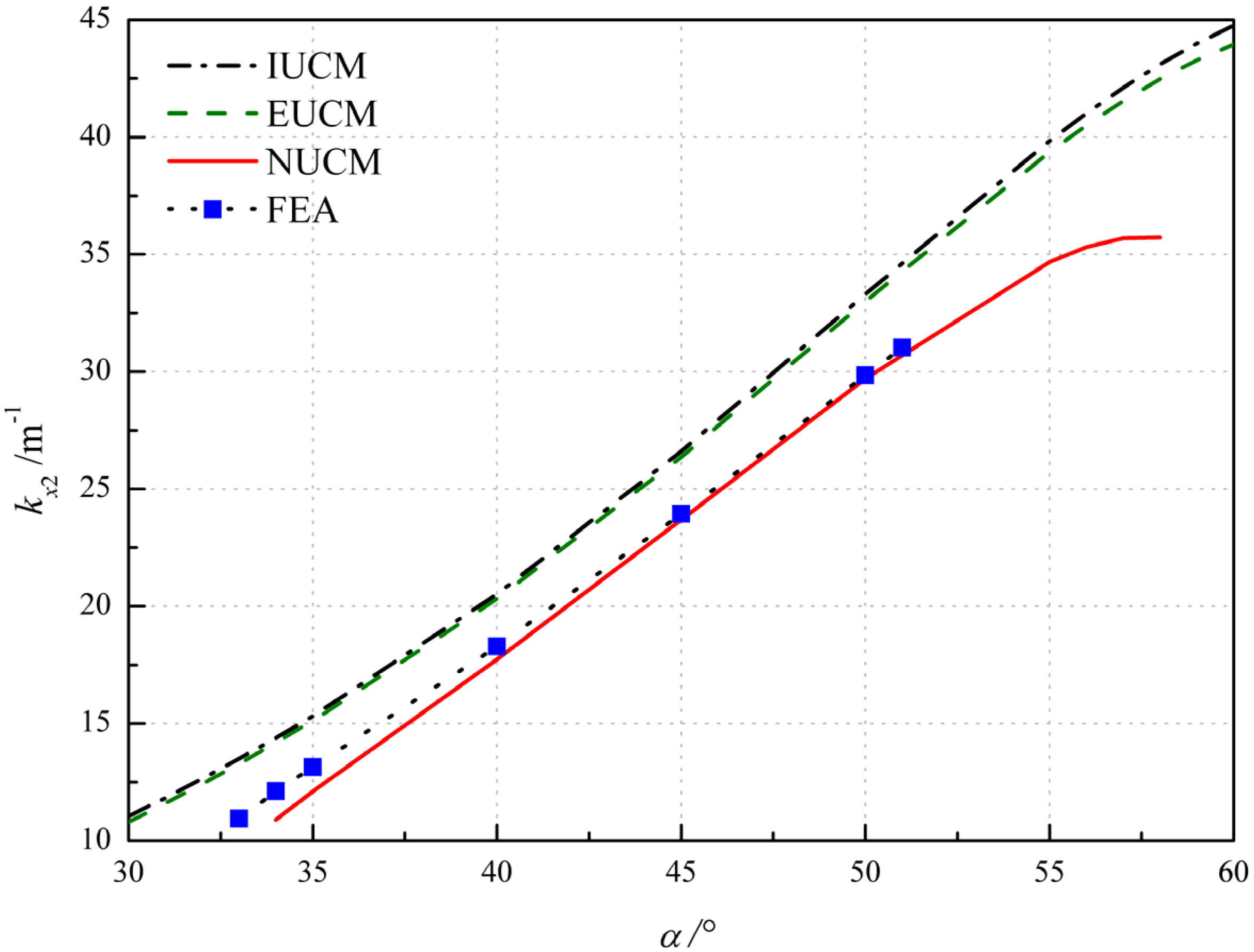
The influence of the angle of layup α is investigated by varying α in the layup of [α/−α/α/−α], (see Figure 5). The IUCM, EUCM, NUCM and FEA predict that the bistability exists at the layup angle ranging from 30° to 60°, 30° to 60°, 34° to 58°and 33° to 51°, respectively. All of them show a gradually increasing trend of principle curvature kx2 and demonstrate that the angle of layup has significant influence on the bistability of anti-symmetric cylindrical shells. The results from NUCM agree well with FE results within the overlap range of layup angle. The discrepancy between results of NUCM and FEA reaches the minimum value 1% at α = 45°, and increases as α is drawn apart from 45°, not exceeding 10%.
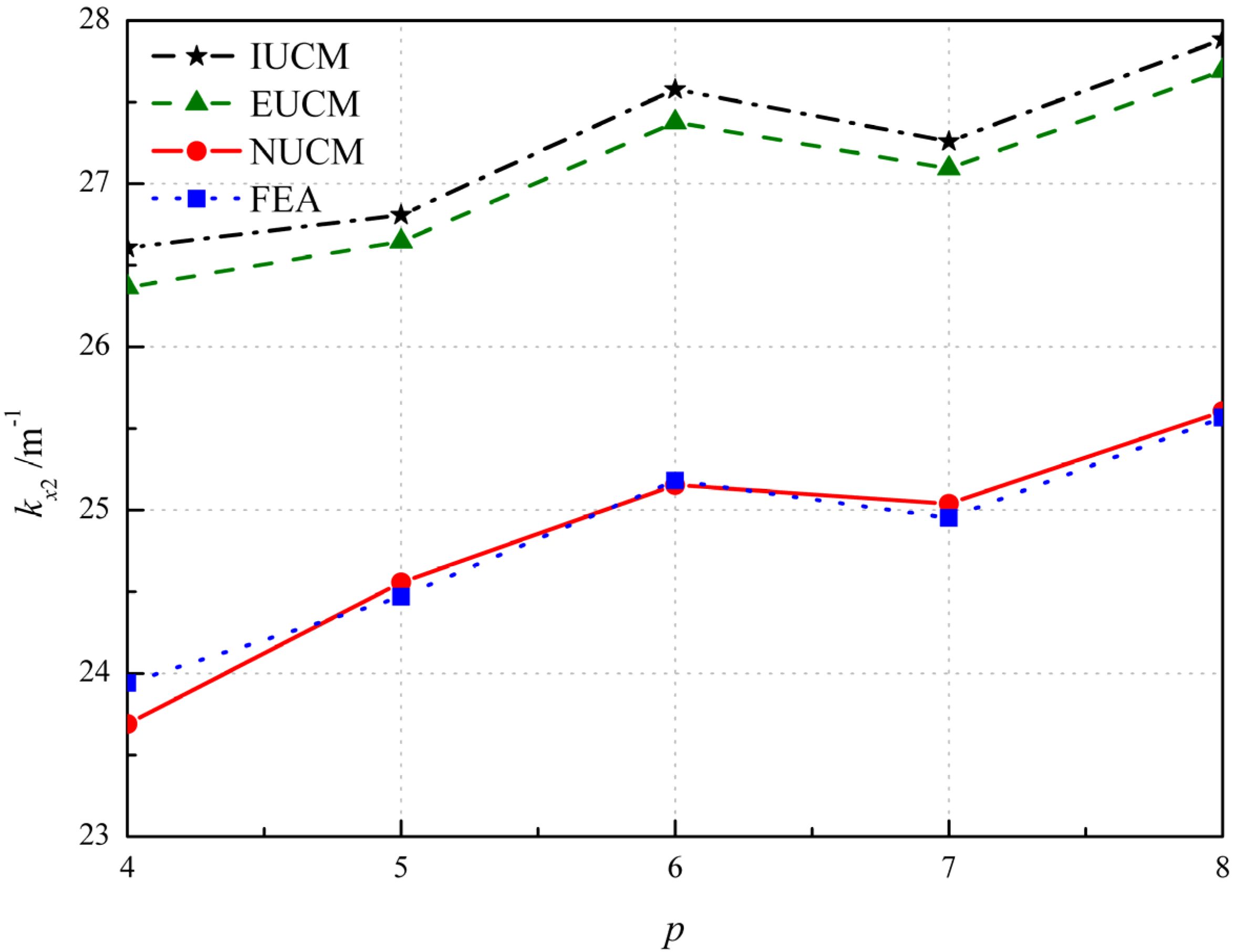
The results of cases with p from 4 to 8 are shown in Figure 6. The influence of the number of plies p on principal curvature kx2 is based on the layup with α = 45°. It should be noted that the ply angle of the middle ply is zero when p is odd. For example, when p = 4 and 5, the layups are [α/−α/α/−α] and [α/−α/0°/α/−α], respectively. In these two cases, the total thickness is the same, but the thickness of each single layer is different. It is seen in Figure 6 that the analytical and FE results show a similar trend and the number of plies p has a little influence on the principal curvature kx2. The discrepancy between the results of NUCM and FEA is approximately within 1%, as seen in Table 3, where the error represents the relative error between results from FEA and NUCM.
Additionally, the influence of material parameters has not been discussed because they affect the bistability of anti-symmetric cylindrical shell through the dimensionless stiffness parameters, the same as layup parameters do (see Figure 3).

4.2.3. Influence of Geometrical Parameters

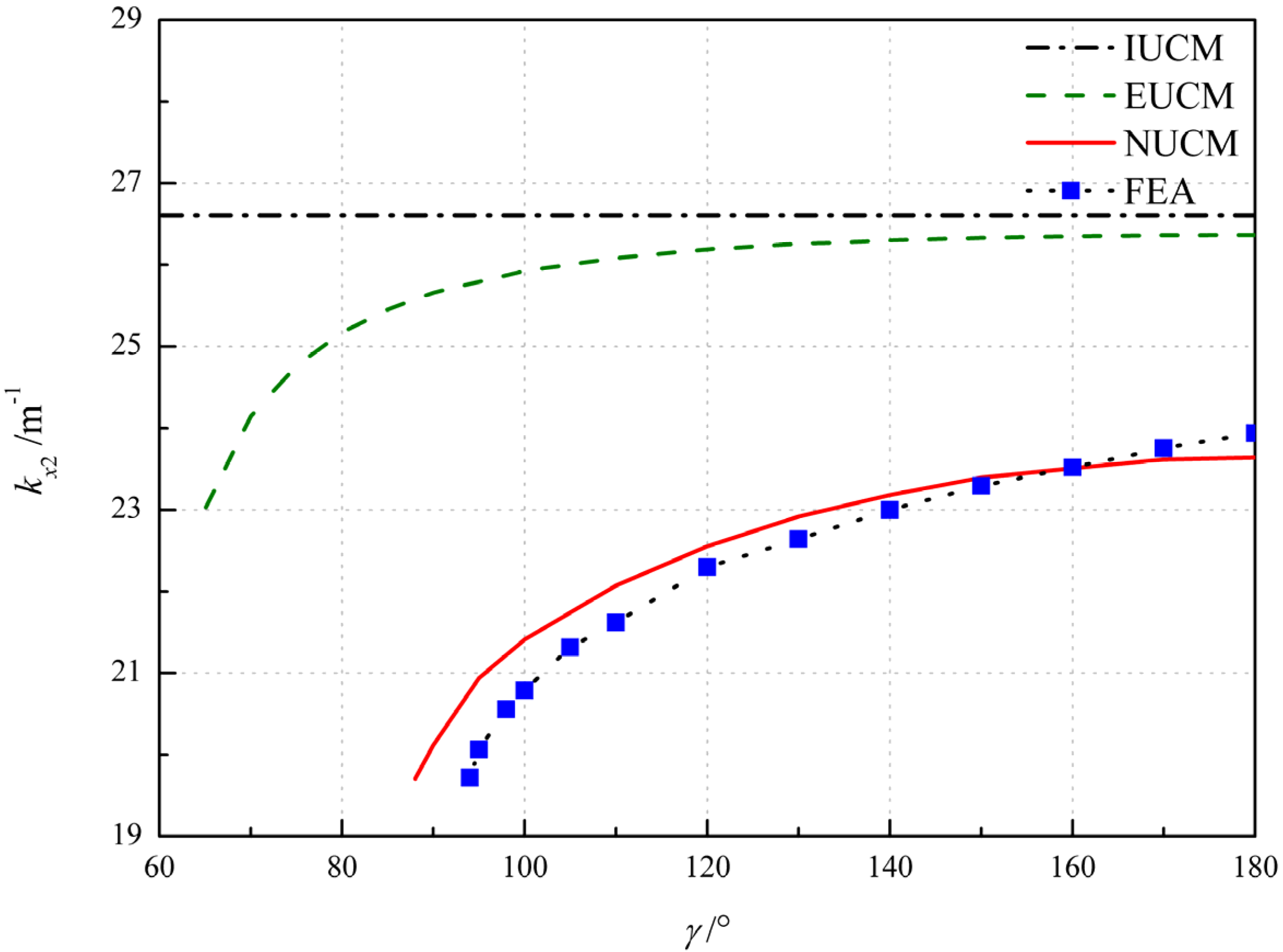
Figure 7 shows the influence of the angle of embrace γ and comparison the analytical and FE results. For IUCM, the principal curvature kx2 are constant irrespective of the variation of γ and the disappearance of bistability is unable to be predicted. As the extensible deformation assumption applied, the disappearance of bistability can be predicted, with the critical value of γ = 63°, 88° and 94° for EUCM, NUCM and FEA, respectively, and then the principal curvature kx2 gradually increases with the increase in γ (see Figure 7). The results from NUCM and FEA agree well with the relative error below 5%, as seen in Table 4 where the error represents error between results from FEA and NUCM.
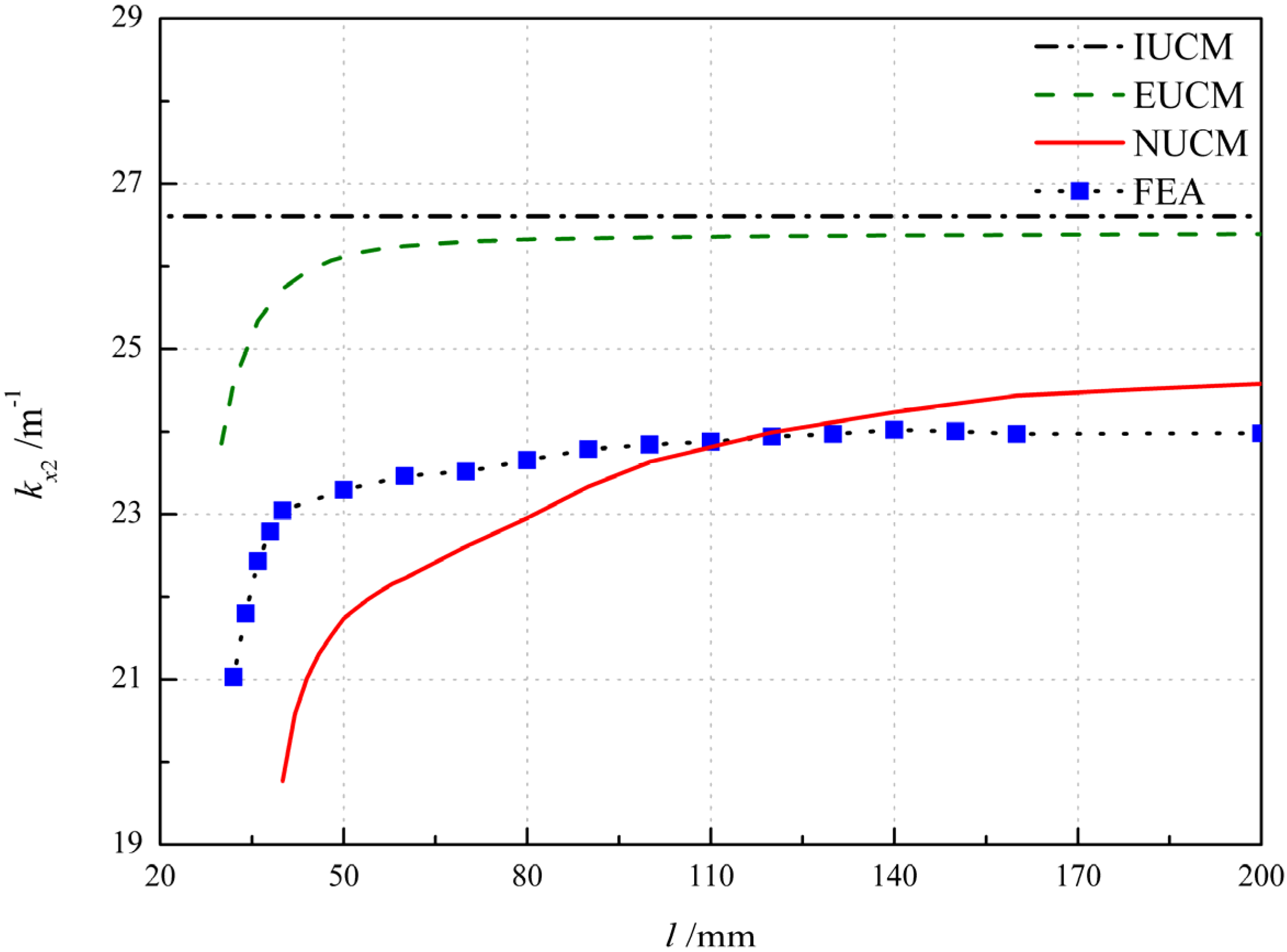
For IUCM, the principal curvature kx2 are constant, irrespective of the variation of l and the disappearance of bistability is unable to be predicted as well. As the extensible deformation assumption is applied, the influence of the longitudinal length l on the principal curvature can be predicted, as shown in Figure 8, with the critical values of l = 30, 40 and 32 mm for EUCM, NUCM and FEA, respectively. In fact, the anti-symmetric cylindrical shell with sufficiently large length tends to roll up in the second equilibrium configuration, and thus kx2 tends to be a constant. As the increase in l occurs, the principal curvatures kx2 of EUCM and FEA show a similar trend and tend to be constant when the length is over 60 and 100 mm, respectively. In contrast, the kx2 of NUCM gradually increases and converges at a length greater than 160 mm. Nonetheless, difference between the results of NUCM and numerical results (1.0 m−1 on average) is closer to that between the results of EUCM and numerical results (2.6 m−1 on average), as shown in Figure 8.
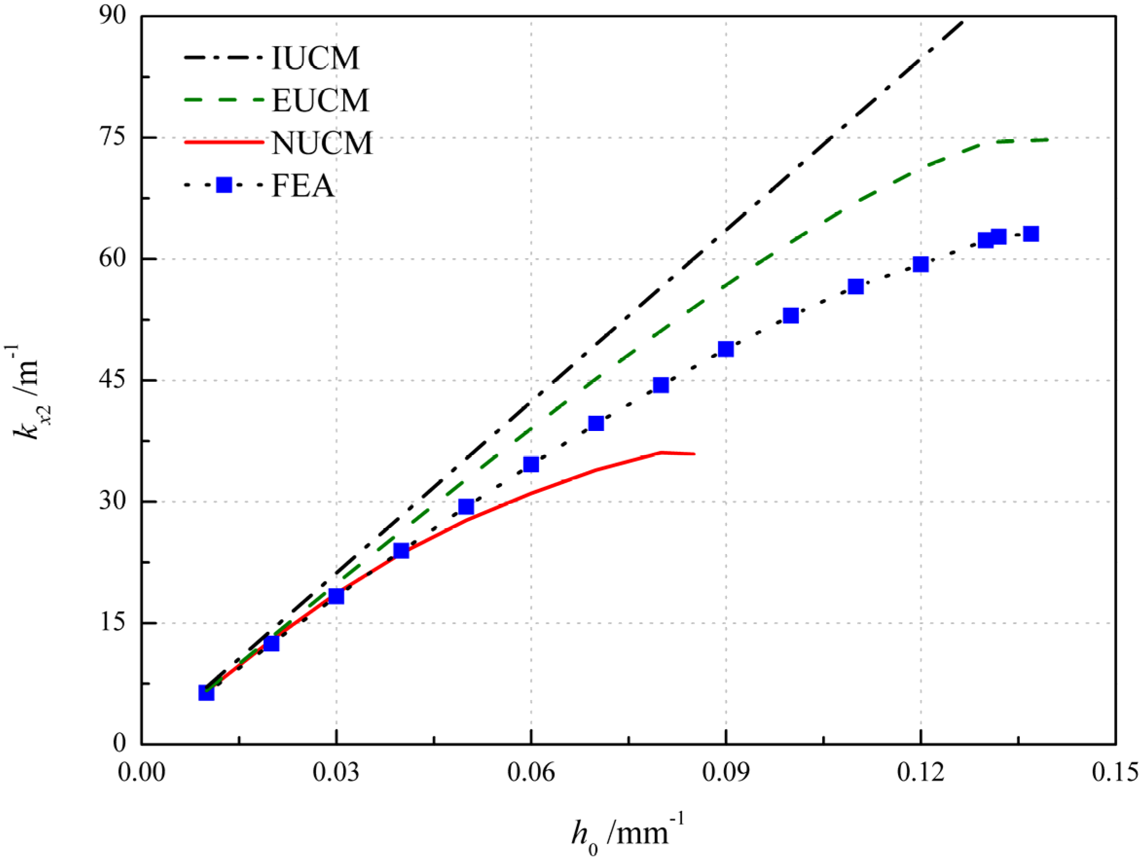
The influence of the initial natural curvature h0 is shown in Figure 9 in which the initial natural curvature changes while keeping the aspect ratio r unchanged. According to IUCM, the principal curvature kx2 can be simply calculated as kx2 = vdh0. In addition, as the initial curvature increases, the principal curvature kx2 grows, with the critical values of h0 = 0.140, 0.085 and 0.137 mm−1 for EUCM, NUCM and FEA, respectively. A sensible increment of the principal curvature is observed in Figure 9 for numerical results and results obtained by EUCM and NUCM, which show the disappearance of bistability. It can be seen that the numerical results agree well with the results obtained by NUCM for small initial natural curvature, as listed in Table 5 where the error-1 and error-2 represent the relative error between the results of FEA and EUCM and that of FEA and NUCM, respectively. Whilst for large initial natural curvature the results obtained by EUCM are more reliable in terms of the relative error and critical value. The possible reason for the increasing error is that a large value of h0 may violate the thin shallow shell assumption [34] when the total thickness is unchanged.
The influence of the anti-symmetric cylindrical shell with different planform shapes is investigated by EUCM, NUCM and FEA in Table 6, where the error-1 and error-2 represent the relative error between results from FEA and EUCM and that from FEA and NUCM, respectively. Three different planform shapes are considered, as shown in Figure 1. The geometric parameters are: a = 60 mm, b = 25 mm, c = 5 mm. Theoretically, for NUCM, the planform shapes influence the bistability of anti-symmetric cylindrical shells through the integral region in Equation (8) and the scalar factor ψij (i,j = 1,2,3,4), but only through a single scalar factor ψ11 for EUCM. With the change in planform shape, the scalar factor ψ11 changes slightly, resulting in the slightly deviation of the results of EUCM. The decline and increase in principal curvature kx2 are found for results of EPS and TPS from EUCM, respectively, compared to the principal curvature of RPS. However, the contrary results are found based on the FEA results as listed in Table 6, which indicates the lower inaccuracy of EUCM for the prediction of planform effects of anti-symmetric cylindrical shells. Compared to principal curvature of RPS, the increase in principal curvature kx2 of EPS is correctly predicted using NUCM. In addition, a more accurate result is obtained from NUCM in contrast with the result from EUCM, as shown in error-1 and error-2 in Table 6. Although the decline in principal curvature kx2 of TPS is not predicted, the relative error between the results from the analytical model and simulation are reduced by utilizing NUCM, as listed in Table 6.
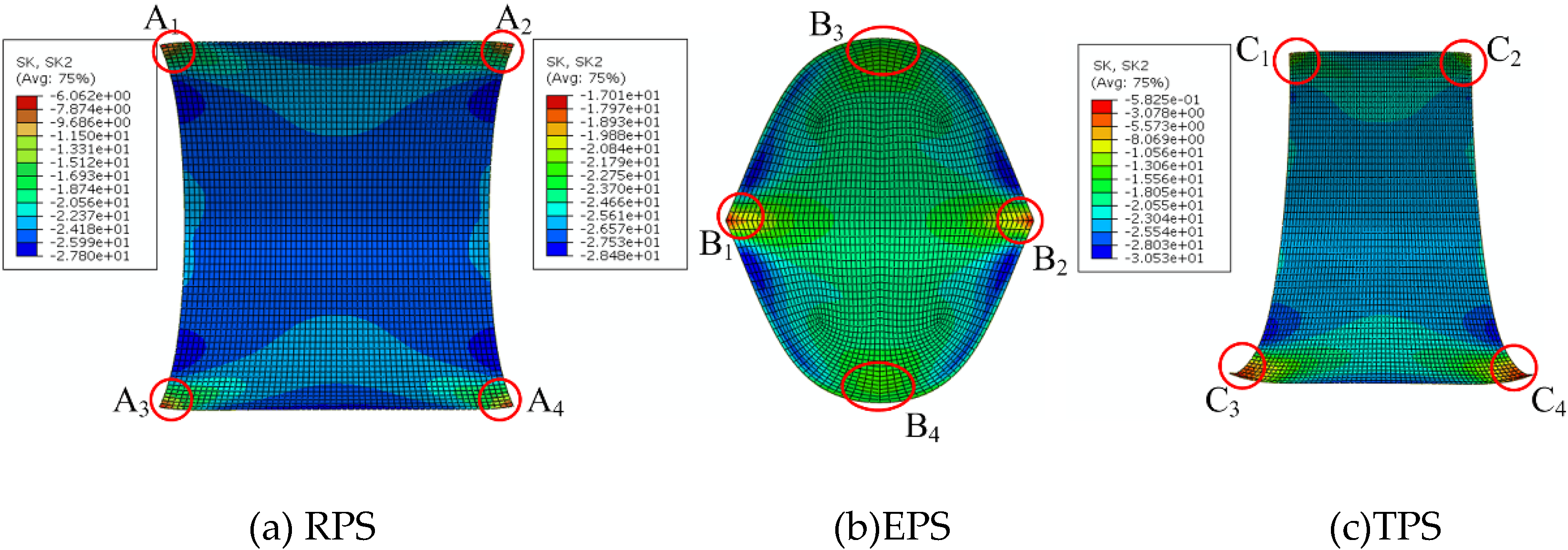
The possible reason for the deviation between results of TPS from analytical model may lay on the difference of bending boundary effect for different planform shapes [44,45]. The bending boundary effect develops for any configuration other than the base state and is due to the disequilibrium of the bending moment. The change in local curvature occurs as the bending moment is equilibrated by the out-of-plane shear stress, which results in the change in average curvature. The local curvatures discussed later are absolute values. Due to the bending boundary effect, the local curvatures in the corner and edge of RPS decrease and increase, respectively (see Figure 10a), where A1, A2, A3, A4 are labeled as the region near the corner; the local curvatures of EPS decrease near the region B1, B2, B3, B4 and increase in the edge between them (see Figure 10b); the local curvatures of TPS decrease obviously near the region C3, C4 and less obviously near the region C1, C2 (see Figure 10c). The increase in local curvature of EPS is greater than that of RPS, as shown in Figure 10, which demonstrates the greater average principal curvature kx2 of EPS. The curvature distribution of TPS is similar to that of RPS, and the decrease in local curvature of TPS is apparent, which demonstrates the smaller average principal curvature kx2 of TPS, compared to that of RPS. However, in the NUCM, the transverse displacement for TPS is chosen to be the same as that for RPS for simplicity, which may be the reason why the results of TPS from NUCM are large.

5. Conclusions

This paper proposes a non-uniform curvature model with five degrees of freedom to investigate the bistability of the anti-symmetric cylindrical shells. Additionally, a plug-in based on the python script is established through ABAQUS software, with the ability of parameter modeling for the anti-symmetric cylindrical shell with rectangular, elliptical and trapezoidal planforms and automatic postprocessing of the equilibrium configurations and the load-displacement curves during the snap process. The accuracy of the presented model is verified by the finite element simulation and the comparison with EUCM and IUCM. Moreover, the effects of various factors for the bistability of the anti-symmetric cylindrical shells are studied. The results indicate that the angle of layup α and the initial natural curvature h0 are the major factors influencing the principal curvature. The angle of embrace γ, the longitudinal length l and the number of plies p have lesser impact on the principal curvature, not as predicted in IUMC for the former two factors. The planform effects of anti-symmetric cylindrical shells are investigated. The results between analytical model and simulation of RPS and EPS correlate well, whilst a certain error exists in the results between the analytical model and simulation of TPS, as shown in Table 6. The possible reason has been discussed. In this respect, more appropriate approximation polynomials for the transverse displacement field corresponding to each planform shape should be considered. Moreover, higher order or more complex approximation polynomials might be considered for the transverse displacement field so as to overcome the limitation and improve the versatility of the presented model. Further investigations are undergoing to better understand the planform effects on the bistability of anti-symmetric cylindrical shells.

Author Contributions

Investigation, X.L.; Methodology, S.J.; Writing – original draft, X.Y.; Writing – review & editing, Z.Z., H.W. (Helong Wu), M.S. and H.W. (Huaping Wu). All authors have read and agreed to the published version of the manuscript.

Funding

This research was funded by the National Natural Science Foundation of China (Grant Nos. 51675485, 11672269, 51775510, 11972323), the Zhejiang Provincial Natural Science Foundation of China (Grant Nos. LR18E050002, LR20A020002), the Fundamental Research Funds for the Provincial Universities of Zhejiang (RF-B2019004).

Conflicts of Interest

The authors declare no conflict of interest.

Appendix A

This section details the modelling assumptions and the procedure used in the Section 2. In order to model the non-linear deformation of thin shallow shells, the FVK assumptions [40] are used. Two primary unknown displacements fields: in-plane displacement, namely u = (ux,uy), and transverse displacement, namely w, are described. With reference to an initially flat configuration, the Gaussian compatibility is obtained [32]
2 ε y x 2 + 2 ε x y 2 2 2 ε x y x y = k x k y k x y 2
where the in-plane distortion ε = ( ε x , ε y , 2 ε x y ) T and the curvature k = ( k x , k y , 2 k x y ) T are given by [33]
ε x = u x x + 1 2 ( w x ) 2 , ε y = u y y + 1 2 ( w y ) 2 , ε x y = 1 2 ( u x y + u y x + 2 w x y ) k x = 2 w x 2 , k y = 2 w y 2 , k x y = 2 w x   y
The compatibility is transformed in terms of stresses and curvatures, which has been shown in Equation (4) in Section 2. By substituting the transverse displacements (5) and (6) into Equation (4), respectively, ΔG for each W can be written in a same form as shown in Equation (7), in which
S 1 = s 1 s 2 s 3 2 G H s 2 s 4 r r s 1 s 5 + s 4 s 5 S 2 = 12 s 2 s 4 + 12 s 4 s 5 r S 3 = 12 s 1 s 5 12 s 4 s 5 / r S 4 = 144 s 4 s 5
for the transverse displacement (5) and
S 1 = s 1 s 2 s 3 2 G H s 2 s 4 π r s 1 s 5 r π + s 4 s 5 π 2 S 2 = 4 s 2 s 4 + 4 r s 4 s 5 π S 3 = 4 s 1 s 5 4 s 4 s 5 π r S 4 = 16 s 4 s 5
for the transverse displacement (6), and GH represents the initial dimensionless natural Gaussian curvature.
Ti (I = 1, 2, 3, 4) in Equation (7) is 2 × 2 tensor function giving the stress distribution obtained by solving the elliptic problem [35]
d i v T i = 0 i n Ω , T i n = 0 o n Ω β a v a β a v a 2 2 T i X Y 2 + 1 v a β a v a 2 2 T i Y X 2 2 γ a 2 T i X Y X Y = G i i n Ω
in which for I = 1,2,3,4, Gi = 1, X2, Y2, X2Y2 in order. The elliptic problem is actually a standard plane-elasticity problem and is solved within the FEniCS framework using the python code in Ref. [35]. Note the region Ω should be axisymmetrical, which is limited by the stress-free boundary condition of shells.

References

  1. Zhang, Z.; Li, Y.; Yu, X.; Li, X.; Wu, H.; Wu, H.; Jiang, S.; Chai, G. Bistable morphing composite structures: A review. Thin-Walled Struct. 2019, 142, 74–97. [Google Scholar] [CrossRef]
  2. Daynes, S.; Weaver, M. Review of shape-morphing automobile structures: Concepts and outlook. Proc. Inst. Mech. Eng. Part D 2013, 227, 1603–1622. [Google Scholar] [CrossRef]
  3. Kuder, I.; Fasel, U.; Ermanni, P.; Arrieta, A.F. Concurrent design of a morphing aerofoil with variable stiffness bi-stable laminates. Smart Mater. Struct. 2016, 25, 115001. [Google Scholar] [CrossRef]
  4. Zhang, Z.; Ma, W.; Wu, H.; Wu, H.; Jiang, S.; Chai, G. A rigid thick Miura-Ori structure driven by bistable carbon fibre-reinforced polymer cylindrical shell. Compos. Sci. Technol. 2018, 167, 411–420. [Google Scholar] [CrossRef]
  5. Ma, W.; Zhang, Z.; Zhang, H.; Li, Y.; Wu, H.; Jiang, S.; Chai, G. An origami-inspired cube pipe structure with bistable anti-symmetric CFRP shells driven by magnetic field. Smart Mater. Struct. 2019, 28, 025028. [Google Scholar] [CrossRef]
  6. Kim, S.; Koh, J.; Lee, J.; Ryu, J.; Cho, M.; Cho, K. Flytrap-inspired robot using structurally integrated actuation based on bistability and a developable surface. Bioinspiration Biomim. 2014, 9, 036004. [Google Scholar] [CrossRef]
  7. Zhang, Z.; Li, X.; Yu, X. Magnetic actuation bionic robotic gripper with bistable morphing structure. Compos. Struct. 2019, 229, 111422. [Google Scholar] [CrossRef]
  8. Zhang, Z.; Chen, D.; Wu, H.; Bao, Y.; Chai, G. Non-contact magnetic driving bioinspired Venus flytrap robot based on bistable anti-symmetric CFRP structure. Compos. Struct. 2016, 135, 17–22. [Google Scholar] [CrossRef] [Green Version]
  9. Chiacchiari, S.; Romeo, F.; McFarland, D.M.; Bergman, L.A.; Vakakis, A.F. Vibration energy harvesting from impulsive excitations via a bistable nonlinear attachment—Experimental study. Mech. Syst. signal Process. 2019, 125, 185–201. [Google Scholar] [CrossRef]
  10. Pan, D.; Ma, B.; Dai, F. Experimental investigation of broadband energy harvesting of a bi-stable composite piezoelectric plate. Smart Mater. Struct. 2017, 26, 035045. [Google Scholar] [CrossRef]
  11. Hamouche, W.; Maurini, C.; Vidoli, S.; Vincenti, A. Multi-parameter actuation of a neutrally stable shell: A flexible gear-less motor. Proc. R. Soc. A 2017, 473, 20170364. [Google Scholar] [CrossRef] [PubMed] [Green Version]
  12. Zhang, Z.; Chen, B.; Lu, C.; Wu, H.; Wu, H.; Jiang, S.; Chai, G. A novel thermo-mechanical anti-icing/de-icing system using bi-stable laminate composite structures with superhydrophobic surface. Compos. Struct. 2017, 180, 933–943. [Google Scholar] [CrossRef] [Green Version]
  13. Daynes, S.; Diaconu, C.; Potter, K.; Weaver, P.M. Bistable prestressed symmetric laminates. J. Compos. Mater. 2009, 44, 1119–1137. [Google Scholar] [CrossRef]
  14. Jiang, X.; Pezzulla, M.; Shao, H.; Ghosh, T.K.; Holmes, D.P. Snapping of bistable, prestressed cylindrical shells. Europhys. Lett. 2018, 122, 64003. [Google Scholar] [CrossRef] [Green Version]
  15. Kebadze, E.; Guest, S.D.; Pellegrino, S. Bistable prestressed shell structures. Int. J. Solids Struct. 2004, 41, 2801–2820. [Google Scholar] [CrossRef]
  16. Seffen, K.A.; Guest, S.D. Prestressed morphing bistable and neutrally stable shells. J. Appl. Mech. 2011, 78, 011002. [Google Scholar] [CrossRef]
  17. Hyer, M. Some observations on the cured shape of thin unsymmetric laminates. J. Compos. Mater. 1981, 15, 175–194. [Google Scholar] [CrossRef]
  18. Iqbal, K.; Pellegrino, S. Bi-stable composite shells. In Proceedings of the 41st AIAA/ASME/ASCE/AHS/ASC Structures, Structural Dynamics, and Materials Conference and Exhibit, Atlanta, GA, USA, 3–6 April 2000; Volume 3. [Google Scholar]
  19. Zhang, Z.; Wu, H.; He, X.; Wu, H.; Bao, Y.; Chai, G. The bistable behaviors of carbon-fiber/epoxy anti-symmetric composite shells. Compos. Part B 2013, 47, 190–199. [Google Scholar] [CrossRef]
  20. Guest, S.; Pellegrino, S. Analytical models for bistable cylindrical shells. Proc. R. Soc. A 2006, 2067, 839–854. [Google Scholar] [CrossRef]
  21. Seffen, K. ‘Morphing’ bistable orthotropic elliptical shallow shells. Proc. R. Soc. A 2007, 463, 67–83. [Google Scholar] [CrossRef]
  22. Vidoli, S.; Maurini, C. Tristability of thin orthotropic shells with uniform initial curvature. Proc. R. Soc. A 2008, 464, 2949–2966. [Google Scholar] [CrossRef]
  23. Iqbal, K.; Pellegrino, S.; Daton-Lovett, A. Bi-stable composite slit tubes. In IUTAM-IASS Symposium on Deployable Structures: Theory and Applications; Springer: Dordrecht, The Netherlands, 2000; pp. 153–162. [Google Scholar]
  24. Galletly, D.A.; Guest, S.D. Bistable composite slit tubes. I. A beam model. Int. J. Solids Struct. 2004, 41, 4517–4533. [Google Scholar] [CrossRef]
  25. Galletly, D.A.; Guest, S.D. Bistable composite slit tubes. II. A shell model. Int. J. Solids Struct. 2004, 41, 4503–4516. [Google Scholar] [CrossRef]
  26. Zhang, Z.; Li, Y.; Wu, H.; Chen, D.; Yang, J.; Wu, H.; Jiang, S.; Chai, G. Viscoelastic bistable behaviour of antisymmetric laminated composite shells with time-temperature dependent properties. Thin-Walled Struct. 2018, 122, 403–415. [Google Scholar] [CrossRef]
  27. Zhang, Z.; Wu, H.; Ye, G.; Yang, J.; Kitipornchai, S.; Chai, G. Experimental study on bistable behaviour of anti-symmetric laminated cylindrical shells in thermal environments. Compos. Struct. 2016, 144, 24–32. [Google Scholar] [CrossRef]
  28. Zhang, Z.; Wu, H.; Ye, G.; Wu, H.; He, X.; Chai, G. Systematic experimental and numerical study of bistable snap processes for anti-symmetric cylindrical shells. Compos. Struct. 2014, 112, 368–377. [Google Scholar] [CrossRef]
  29. Zhang, Z.; Ye, G.; Wu, H.; Yang, J.; Kitipornchai, S.; Chai, G. Bistable behaviour and microstructure characterization of carbon fiber/epoxy resin anti-symmetric laminated cylindrical shell after thermal exposure. Compos. Sci. Technol. 2017, 138, 91–97. [Google Scholar] [CrossRef] [Green Version]
  30. Zhang, Z.; Ye, G.; Wu, H.; Chen, D.; Chai, G. Thermal effect and active control on bistable behaviour of anti-symmetric composite shells with temperature-dependent properties. Compos. Struct. 2015, 124, 263–271. [Google Scholar] [CrossRef] [Green Version]
  31. Chai, H.; Li, Y.; Zhang, Z.; Sun, M.; Wu, H.; Jiang, S. Systematic analysis of bistable anti-symmetric composite cylindrical shells and variable stiffness composite structures in hygrothermal environment. Int. J. Adv. Manuf. Technol. 2020, 1–17. [Google Scholar] [CrossRef]
  32. Calladine, C. Theory of Shell Structures; Cambridge university press: Cambridge, UK, 1989. [Google Scholar]
  33. Fernandes, A.; Maurini, C.; Vidoli, S. Multiparameter actuation for shape control of bistable composite plates. Int. J. Solids Struct. 2010, 47, 1449–1458. [Google Scholar] [CrossRef] [Green Version]
  34. Hamouche, W.; Maurini, C. Vincenti, A.; Vidoli, S. Basic criteria to design and produce multistable shells. Meccanica 2016, 51, 2305–2320. [Google Scholar] [CrossRef] [Green Version]
  35. Vidoli, S. Discrete approximations of the Föppl–Von Kármán shell model: From coarse to more refined models. Int. J. Solids Struct. 2013, 50, 1241–1252. [Google Scholar] [CrossRef]
  36. Brunetti, M.; Vincenti, A.; Vidoli, S. A class of morphing shell structures satisfying clamped boundary conditions. Int. J. Solids Struct. 2016, 82, 47–55. [Google Scholar] [CrossRef]
  37. Brunetti, M.; Vidoli, S.; Vincenti, A. Bistability of orthotropic shells with clamped boundary conditions: An analysis by the polar method. Compos. Struct. 2018, 194, 388–397. [Google Scholar] [CrossRef]
  38. Pirrera, A.; Avitabile, D.; Weaver, P.M. Bistable plates for morphing structures: A refined analytical approach with high-order polynomials. Int. J. Solids Struct. 2010, 47, 3412–3425. [Google Scholar] [CrossRef] [Green Version]
  39. Pirrera, A.; Avitabile, D.; Weaver, P. On the thermally induced bistability of composite cylindrical shells for morphing structures. Int. J. Solids Struct. 2012, 49, 685–700. [Google Scholar] [CrossRef] [Green Version]
  40. Ciarlet, P. A justification of the von Kármán equations. Arch. Ration. Mech. Anal. 1980, 73, 349–389. [Google Scholar] [CrossRef]
  41. Logg, A.; Mardal, K.-A.; Wells, G. Automated Solution of Differential Equations by the Finite Element Method: The FEniCS Book; Springer: Berlin/Heidelberg, Germany, 2012. [Google Scholar]
  42. Hyer, M. The room-temperature shapes of four-layer unsymmetric cross-ply laminates. J. Compos. Mater. 1982, 16, 318–340. [Google Scholar] [CrossRef]
  43. Emam, S.; Inman, D. A review on bistable composite laminates for morphing and energy harvesting. Appl. Mech. Rev. 2015, 67, 060803. [Google Scholar] [CrossRef]
  44. Coburn, B.; Pirrera, A.; Weaver, P.M. Vidoli, S. Tristability of an orthotropic doubly curved shell. Compos. Struct. 2013, 96, 446–454. [Google Scholar] [CrossRef]
  45. Giomi, L.; Mahadevan, L. Multi-stability of free spontaneously curved anisotropic strips. Proc. R. Soc. A 2011, 468, 511–530. [Google Scholar] [CrossRef] [Green Version]
Figure 1. Geometrical parameters of cylindrical shells with different planform shapes.
Polymers 12 01001 g001
Figure 2. The process of the plug-in for the bistability analysis of anti-symmetric cylindrical shells.
Polymers 12 01001 g002
Figure 3. Relationships of the direct factors between the numerical model and non-uniform curvature model (NUCM).
Polymers 12 01001 g003
Figure 4. The bistability curves at different scalar factor.
Polymers 12 01001 g004
Figure 5. Variation of the principal curvature with respect to the angle of layup α.
Polymers 12 01001 g005
Figure 6. Variation of the principal curvature with respect to the number of plies p.
Polymers 12 01001 g006
Figure 7. Variation of the principal curvature with respect to the angle of embrace γ.
Polymers 12 01001 g007
Figure 8. Variation of the principal curvature with respect to the longitudinal length l.
Polymers 12 01001 g008
Figure 9. Variation of the principal curvature with respect to the initial natural curvature h0.
Polymers 12 01001 g009
Figure 10. The curvature distribution of kx2 of anti-symmetric cylindrical shells with different planform shapes (vertical view).
Polymers 12 01001 g010
Table 1. Material parameters of T700/Epoxy resin unidirectional lamina [27].
E1/GPaE2/GPaG12(13)/GPav12α1/(10−6/°C)α2/(10−6/°C)
1087.075.170.31−2.164.33
where E1 and E2 refer to the longitudinal and transverse elastic modulus, respectively; ν12 is the in-plane Poisson’s ratio and G12, G13 the shear modulus and α1, α2 are thermal expansion coefficient.
Table 2. Comparison of the average curvatures with analytical models and simulation.
Average CurvatureIUCM [20]EUCM [21]QVCM [35]NUCMFEA
kx2/m−126.6126.3611.9823.6923.94
ky2/m−100.168.012.072.81
Table 3. Principal curvature of anti-symmetric cylindrical shells with different number of plies from analytical model and simulation.
Number of Plies pkx2/m−1(NUCM)kx2/m−1(FEA)Error
423.6923.941.05%
524.5624.47−0.36%
625.1525.180.10%
725.0424.95−0.35%
825.6125.57−0.15%
Table 4. Principal curvature of anti-symmetric cylindrical shells with different angle of embrace from analytical model and simulation.
Angle of Embrace γkx2/m−1(NUCM)kx2/m−1(FEA)Error
18023.6423.941.24%
16023.5123.520.05%
14023.1823.00−0.79%
12022.5522.30−1.14%
10021.4120.78−3.01%
9520.9420.06−4.38%
Table 5. Principal curvature of anti-symmetric cylindrical shells with different initial natural curvature from analytical model and simulation.
h0/mm−1kx2/m−1(EUCM)kx2/m−1(NUCM)kx2/m−1(FEA)Error-1Error-2
0.016.656.606.374.36%3.68%
0.0213.2712.9312.456.62%3.83%
0.0319.8518.6918.308.50%2.12%
0.0426.3623.6923.9410.11%1.04%
0.0532.7827.7029.3611.66%−5.67%
Table 6. Principal curvature of anti-symmetric cylindrical shells with different planform shapes from analytical model and simulation.
Planform Shapekx2/m−1(EUCM)kx2/m−1(NUCM)kx2/m−1(FEA)Error-1Error-2
RPS26.3623.6923.9410.11%−1.04%
EPS26.3023.9824.467.52%−1.96%
TPS26.5424.4822.1619.76%10.47%