Multi-Trigger Thermo-Electro-Mechanical Soft Actuators under Large Deformations


Abstract

1. Introduction
2. Materials and Methods
2.1. Constitutive Equations for Electro-Hyperelastic Elastomers
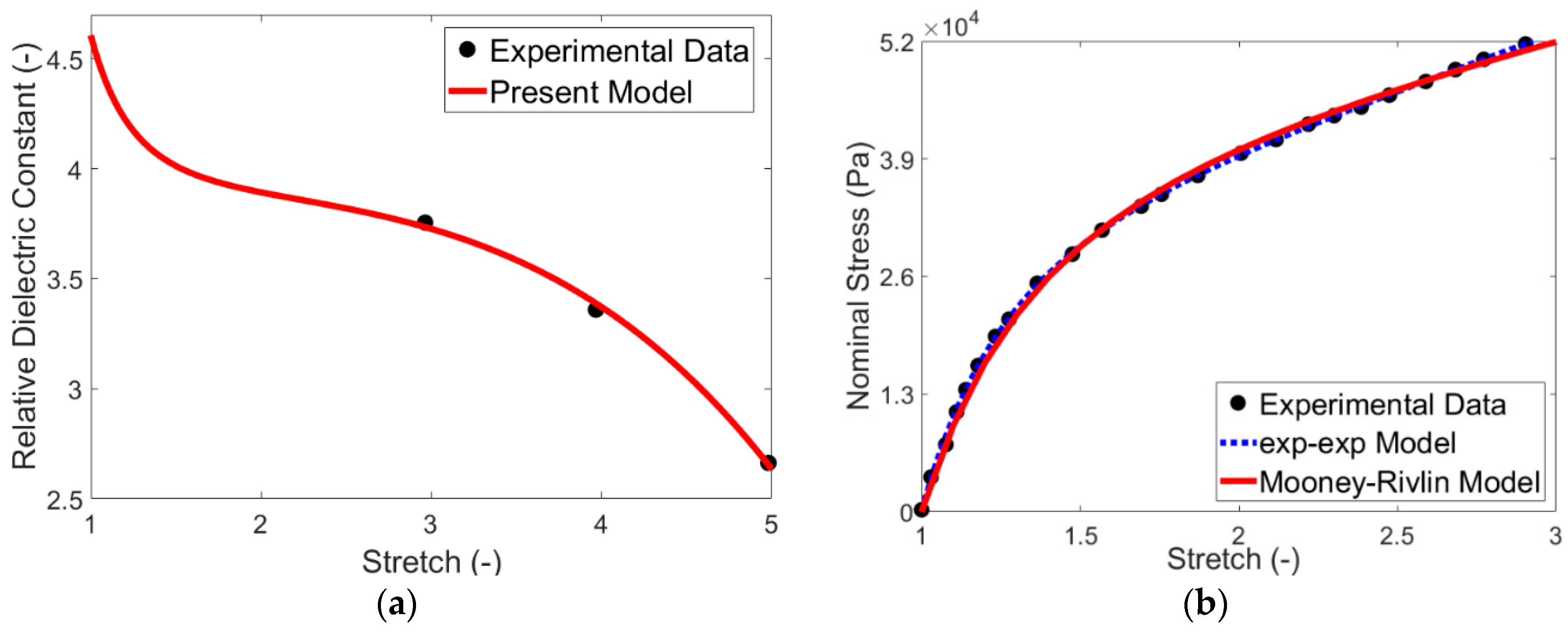
2.2. Material Model Calibration
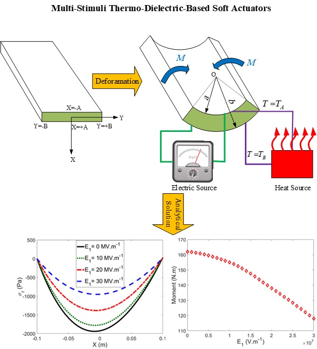
2.3. Non-Linear Continuum Framework of Finite Bending of the Actuator
3. Results
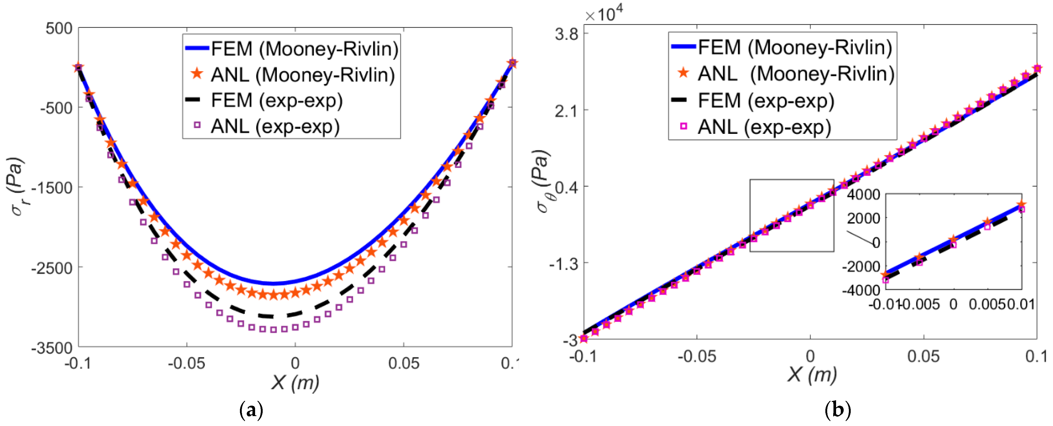
3.1. Verification
3.1.1. Purely Mechanical Deformation
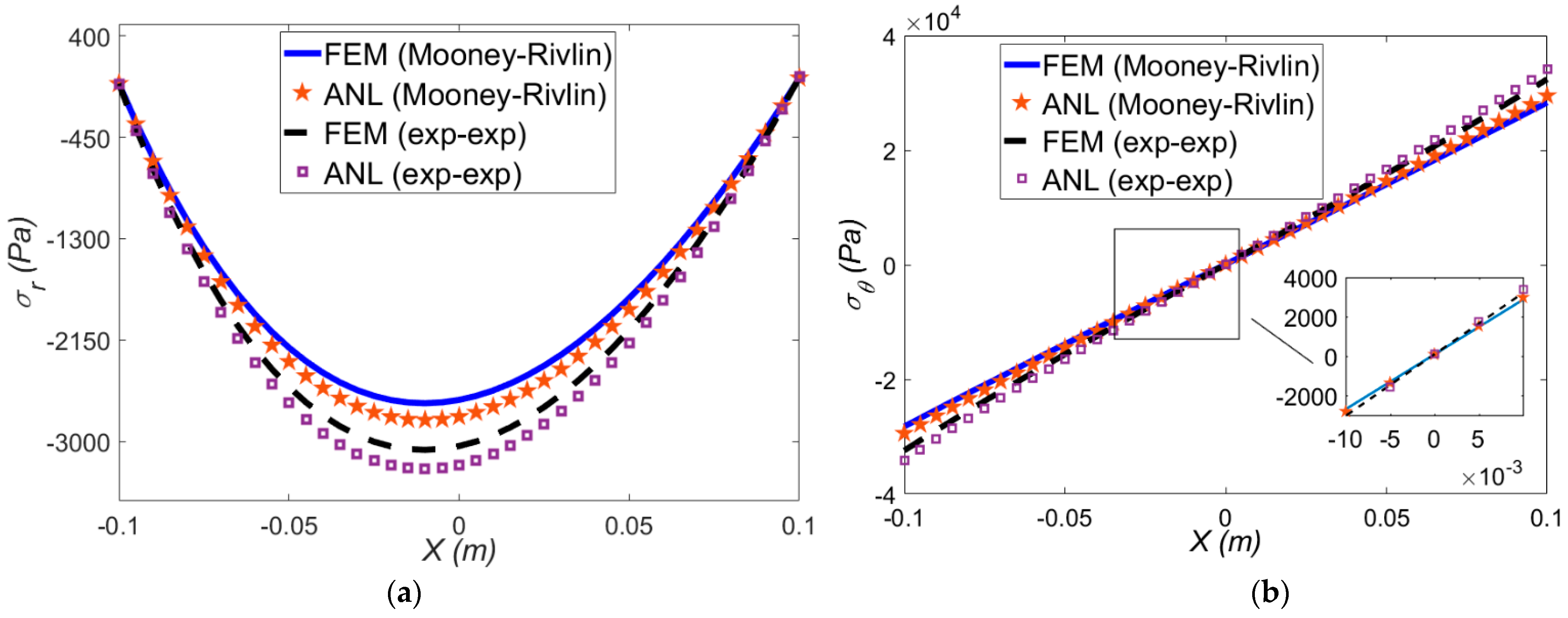
3.1.2. Thermo-Mechanical Deformation
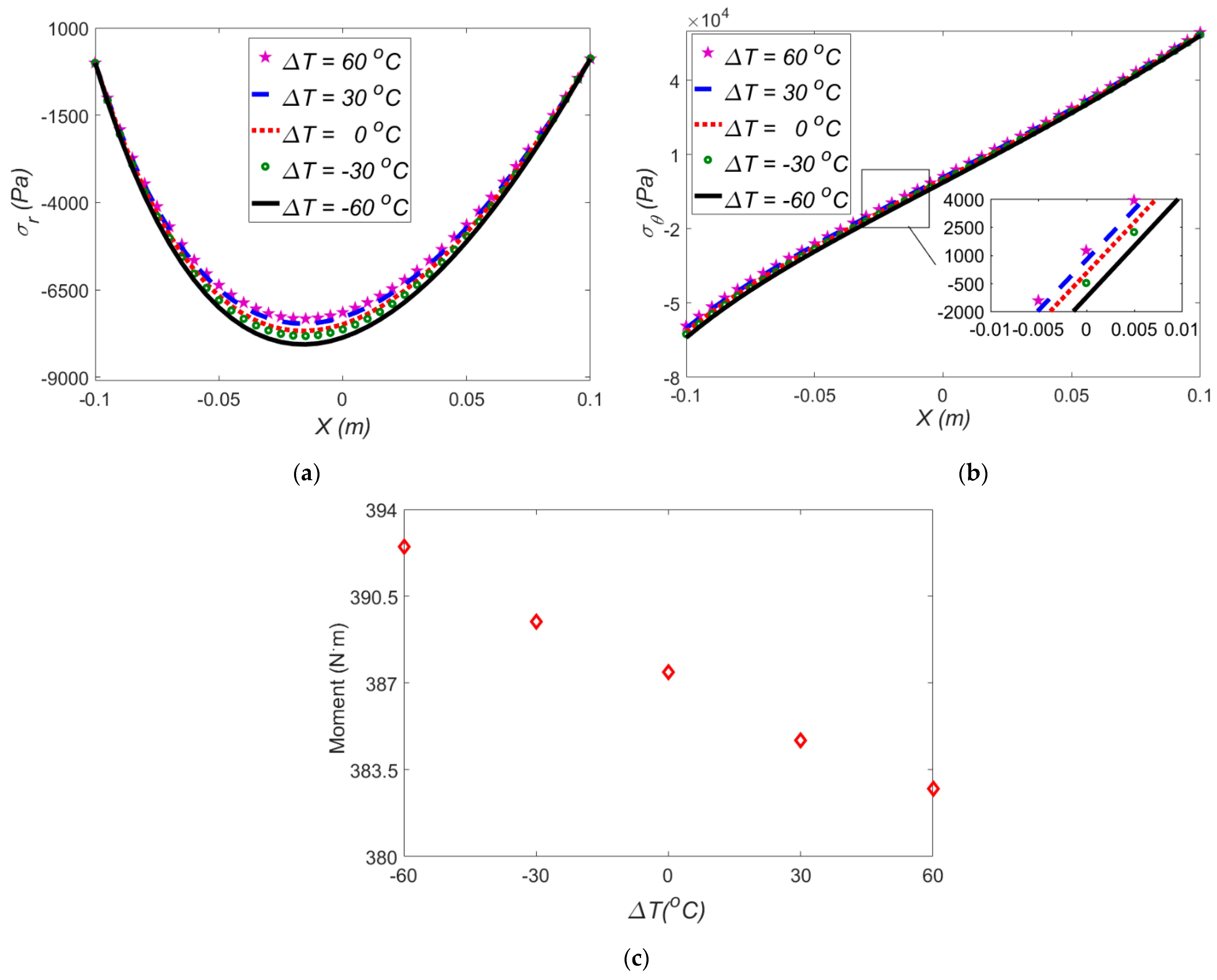
3.2. Effect of Temperature Difference in the Absence of Electric Field
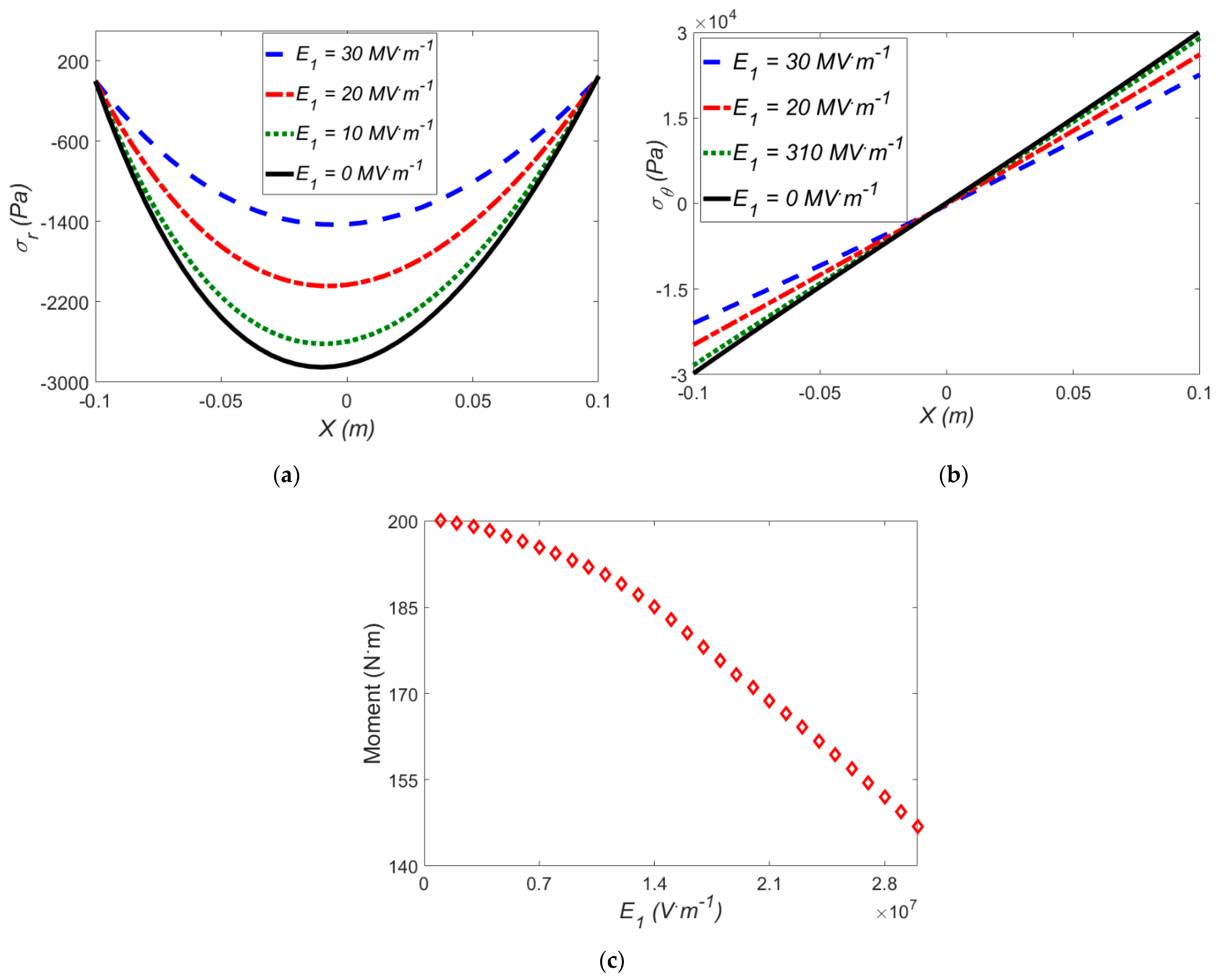
3.3. Effect of an Electric Field in the Absence of Temperature Difference
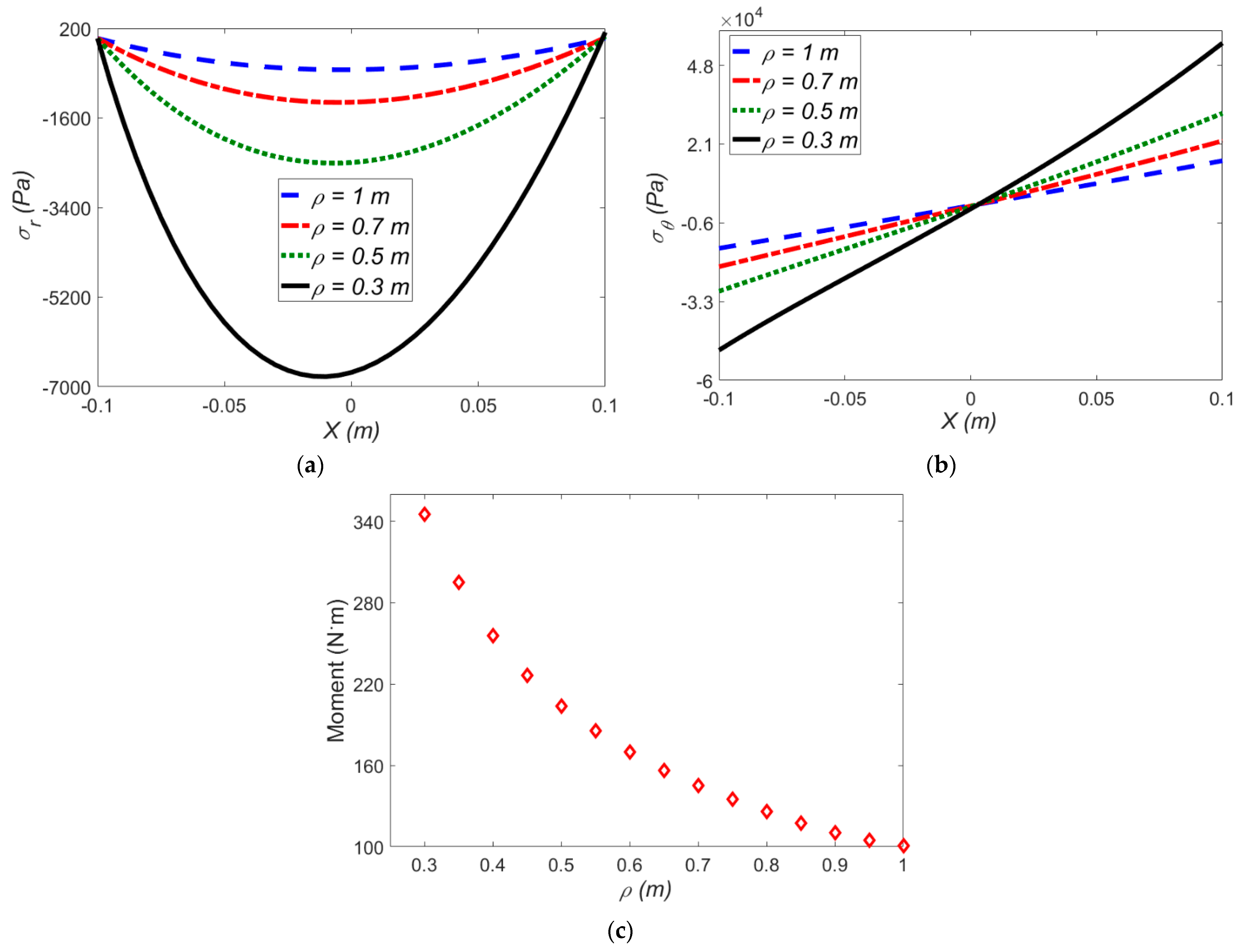
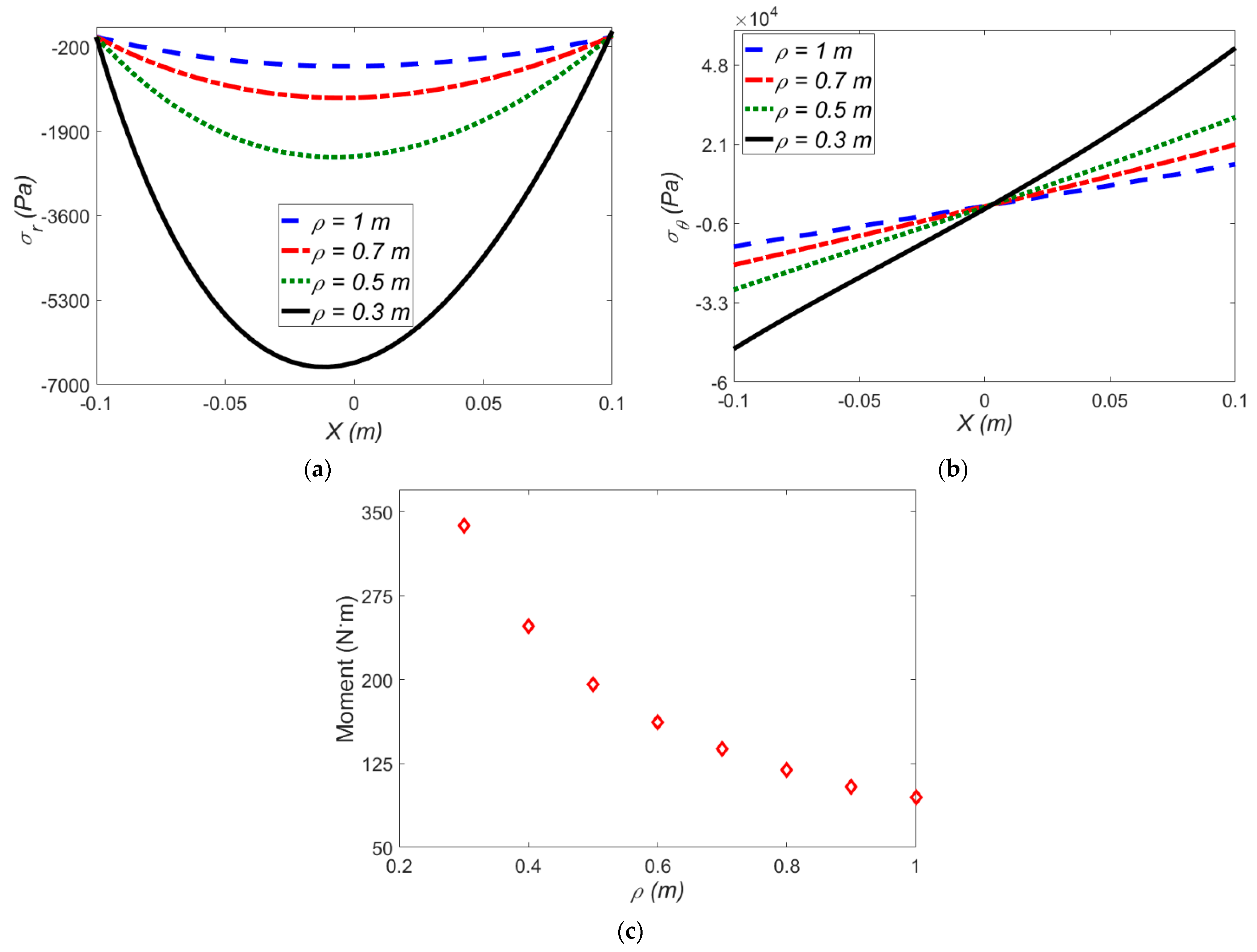
The Effect of Applied Mean Radius of Curvature on the Stress Components and Induced Moment
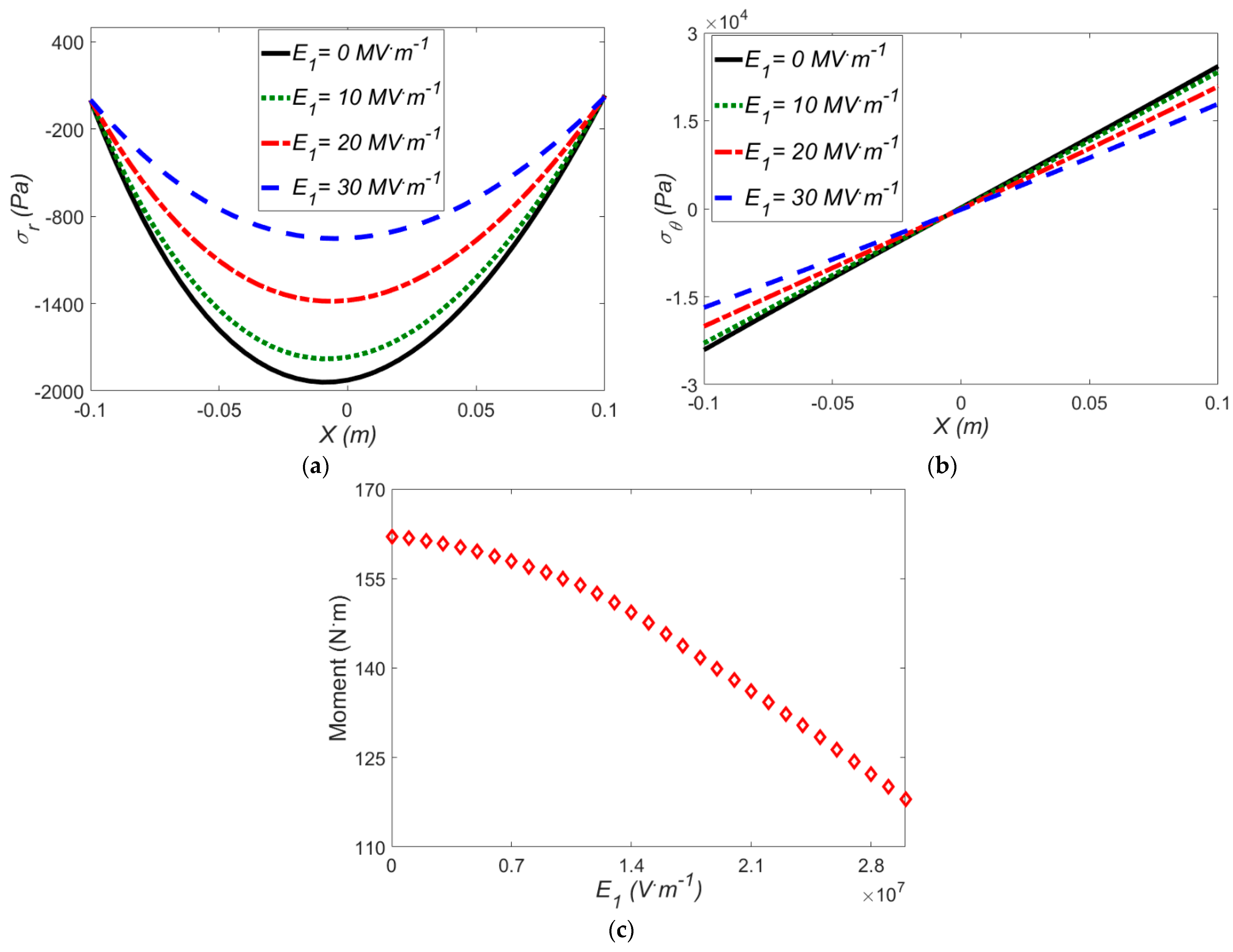
3.4. Thermo-Electro-Mechanical Loading on the Actuator
3.4.1. Effect of Applied Mean Radius of Curvature on the Stress and Induced Moment
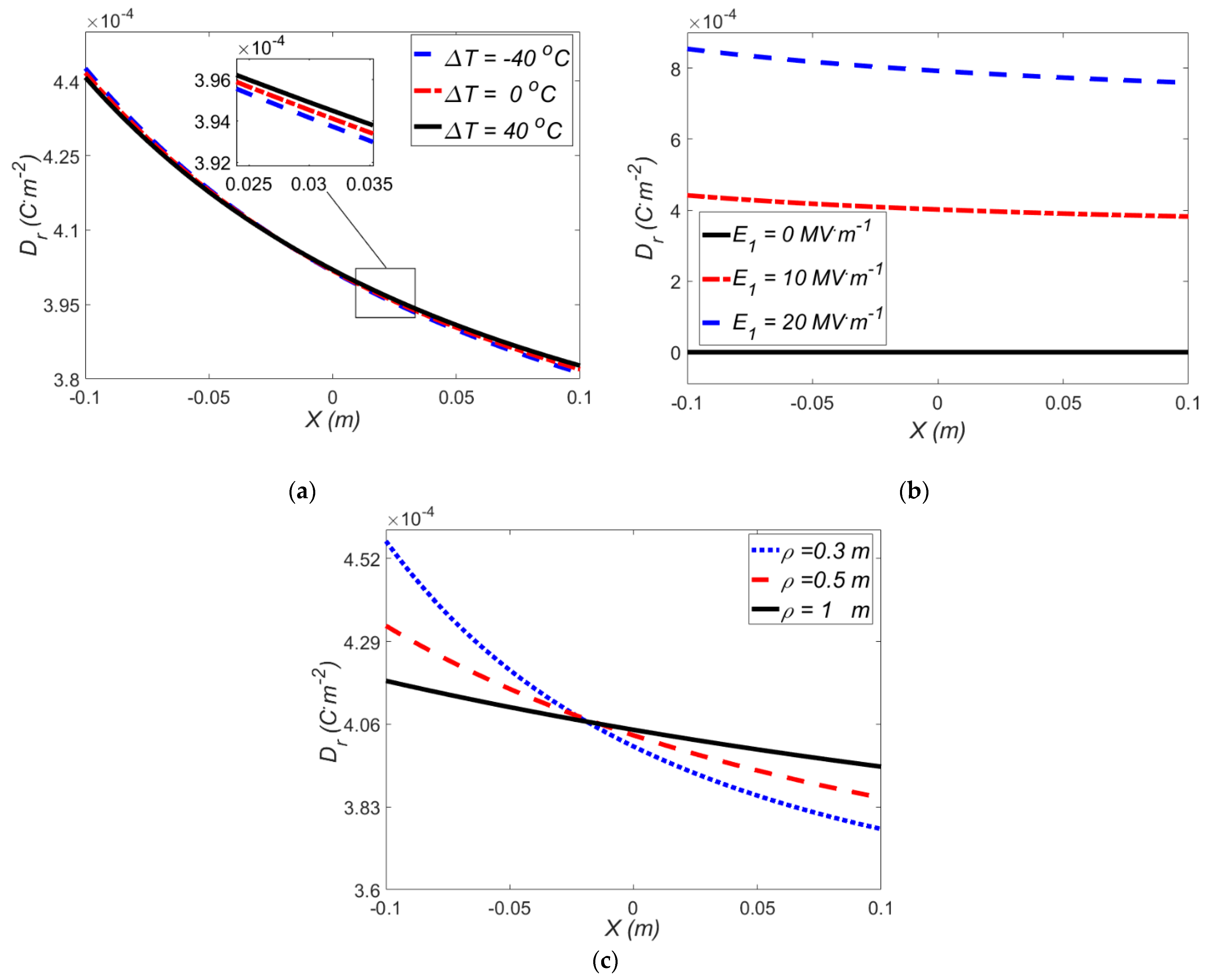
3.4.2. Effect of Electric Field and Temperature Gradient on the Electric Induction
4. Conclusions
- (1)
- By increasing the temperature differences in both sides of the actuator, in the absence of electric field, the amount of radial stress, hoop stress and applied moment are reduced. Moreover, at higher mean radius of curvature, the quantity of both radial and hoop stress is decreased.
- (2)
- Imposing a negative temperature gradient to the beam results in an opposite thermal moment which means a larger mechanical moment should be applied to bend the beam to a desired mean radius of curvature.
- (3)
- Radial stress, hoop stress, and applied moment decrease, with increasing the electro field in the absence of temperature differences, also the radial stress curve becomes more symmetric.
- (4)
- The radial stress decreases by 62% in the presence of a fixed electric field and absence of temperature difference where the applied strain varies from ρ = 0.3 m to ρ = 0.5 m, although in the absence of an electric field, the radial stress drop is 72%.
- (5)
- The effect of electric field on the stress components and applied moment at specified temperature gradients shows that the effect of temperature gradient is entirely in line with the electric field which means at higher temperature gradients we have lower stresses.
- (6)
- The results reveal that due to the thermal expansion of the VHB 4910, the temperature gradient does not have a significant effect on the electric induction, while by increasing the electric field, the amount of the electric induction increases.
Author Contributions
Funding
Conflicts of Interest
References
- Lee, C.; Kim, M.; Kim, Y.J.; Hong, N.; Ryu, S.; Kim, H.J.; Kim, S. Soft robot review. Int. J. Control Autom. Syst. 2017, 15, 3–15. [Google Scholar] [CrossRef]
- Yeo, J.C.; Yap, H.K.; Xi, W.; Wang, Z.; Yeow, C.H.; Lim, C.T. Flexible and stretchable strain sensing actuator for wearable soft robotic applications. Adv. Mater. Technol. 2016, 1, 1600018. [Google Scholar] [CrossRef]
- Zolfagharian, A.; Kouzani, A.Z.; Khoo, S.Y.; Moghadam, A.A.A.; Gibson, I.; Kaynak, A. Evolution of 3D printed soft actuators. Sens. Actuators A Physical. 2016, 250, 258–272. [Google Scholar] [CrossRef]
- Xiang, C.; Guo, J.; Sun, R.; Hinitt, A.; Helps, T.; Taghavi, M.; Rossiter, J. Electroactive textile actuators for breathability control and thermal regulation devices. Polymers 2019, 11, 1199. [Google Scholar] [CrossRef] [PubMed]
- Lin, P.-W.; Liu, C.-H. Bio-inspired soft proboscis actuator driven by dielectric elastomer fluid transducers. Polymers 2019, 11, 142. [Google Scholar] [CrossRef]
- Song, J.; Zhang, Y. From two-dimensional to three-dimensional structures: A superior thermal-driven actuator with switchable deformation behavior. Chem. Eng. J. 2019, 360, 680–685. [Google Scholar] [CrossRef]
- Jia, K.; Wang, M.; Lu, T.; Wang, T. Linear control of multi-electrode dielectric elastomer actuator with a finite element model. Int. J. Mech. Sci. 2019, 159, 441–449. [Google Scholar] [CrossRef]
- Sachyani Keneth, E.; Scalet, G.; Layani, M.; Tibi, G.; Degani, A.; Auricchio, F.; Magdassi, S. Pre-programmed tri-layer electro-thermal actuators composed of shape memory polymer and carbon nanotubes. Soft Robot. 2019. [Google Scholar] [CrossRef]
- Slesarenko, V.; Engelkemier, S.; Galich, P.I.; Vladimirsky, D.; Klein, G.; Rudykh, S. Strategies to control performance of 3d-printed, cable-driven soft polymer actuators: From simple architectures to gripper prototype. Polymers 2018, 10, 846. [Google Scholar] [CrossRef]
- Boyraz, P.; Runge, G.; Raatz, A. An overview of novel actuators for soft robotics. In Actuators; Multidisciplinary Digital Publishing Institute: Basel, Switzerland, 2018; p. 48. [Google Scholar]
- Yarali, E.; Baniassadi, M.; Baghani, M. Numerical homogenization of coiled carbon nanotube reinforced shape memory polymer nanocomposites. Smart Mater. Struct. 2019, 28, 035026. [Google Scholar] [CrossRef]
- Yarali, E.; Mohammadi, A.; Mafakheri, S.; Baghani, M.; Adibi, H. Mathematical modeling and experimental evaluation of a prototype double-tube Magnetorheological damper. SN Appl. Sci. 2019, 1, 1341. [Google Scholar] [CrossRef]
- Bodaghi, M.; Noroozi, R.; Zolfagharian, A.; Fotouhi, M.; Norouzi, S. 4D printing self-morphing structures. Materials 2019, 12, 1353. [Google Scholar] [CrossRef]
- Almomani, A.; Hong, W.; Hong, W.; Montazami, R. Influence of temperature on the electromechanical properties of ionic liquid-doped ionic polymer-metal composite actuators. Polymers 2017, 9, 358. [Google Scholar] [CrossRef] [PubMed]
- Xia, Q.; Xia, L.; Shi, T. Topology optimization of thermal actuator and its support using the level set based multiple–type boundary method and sensitivity analysis based on constrained variational principle. Struct. Multidiscip. Optim. 2018, 57, 1317–1327. [Google Scholar] [CrossRef]
- He, L.; Lou, J.; Du, J.; Wang, J. Finite bending of a dielectric elastomer actuator and pre-stretch effects. Int. J. Mech. Sci. 2017, 122, 120–128. [Google Scholar] [CrossRef]
- Gupta, U.; Qin, L.; Wang, Y.; Godaba, H.; Zhu, J. Soft robots based on dielectric elastomer actuators: A review. Smart Mater. Struct. 2019, 28, 103002. [Google Scholar] [CrossRef]
- Kadooka, K.; Taya, M.; Naito, K.; Saito, M. Modeling of a corrugated dielectric elastomer actuator for artificial muscle applications. In Proceedings of the Electroactive Polymer Actuators and Devices (EAPAD), San Diego, CA, USA, 9–15 March 2015; p. 943020. [Google Scholar]
- Qin, L.; Cao, J.; Tang, Y.; Zhu, J. Soft freestanding planar artificial muscle based on dielectric elastomer actuator. J. Appl. Mech. 2018, 85, 051001. [Google Scholar] [CrossRef]
- Alibakhshi, A.; Heidari, H. Analytical approximation solutions of a dielectric elastomer balloon using the multiple scales method. Eur. J. Mech. A Solids 2019, 74, 485–496. [Google Scholar] [CrossRef]
- Zhang, Q.; Zhang, Z.; Xu, N.; Yang, H. Dielectric properties of P(VDF-TrFE-CTFE) composites filled with surface-coated TiO2 nanowires by SnO2 nanoparticles. Polymers 2020, 12, 85. [Google Scholar] [CrossRef]
- Henke, E.M.; Wilson, K.E.; Anderson, I. Modeling of dielectric elastomer oscillators for soft biomimetic applications. Bioinspir. Biomim. 2018, 13, 046009. [Google Scholar] [CrossRef]
- Wu, T.-H.; Li, X.-Y. Elliptical crack problem in magneto-electro-thermo-elasticity of transversely isotropic materials: 3D analytical and numerical solutions. Int. J. Eng. Sci. 2019, 144, 103136. [Google Scholar] [CrossRef]
- Mehnert, M.; Hossain, M.; Steinmann, P. Numerical modeling of thermo-electro-viscoelasticity with field-dependent material parameters. Int. J. Non Linear Mech. 2018, 106, 13–24. [Google Scholar] [CrossRef]
- Ghobadi, A.; Beni, Y.T.; Golestanian, H. Size dependent thermo-electro-mechanical nonlinear bending analysis of flexoelectric nano-plate in the presence of magnetic field. Int. J. Mech. Sci. 2019, 152, 118–137. [Google Scholar] [CrossRef]
- Nguyen, C.H.; Alici, G.; Mutlu, R. Modeling a soft robotic mechanism articulated with dielectric elastomer actuators. In Proceedings of the 2014 IEEE/ASME International Conference on Advanced Intelligent Mechatronics, Besançon, France, 8–11 July 2014; pp. 599–604. [Google Scholar]
- Goulbourne, N.C. A constitutive model of polyacrylate interpenetrating polymer networks for dielectric elastomers. Int. J. Solids Struct. 2011, 48, 1085–1091. [Google Scholar] [CrossRef]
- Li, T.; Keplinger, C.; Baumgartner, R.; Bauer, S.; Yang, W.; Suo, Z. Giant voltage-induced deformation in dielectric elastomers near the verge of snap-through instability. J. Mech. Phys. Solids 2013, 61, 611–628. [Google Scholar] [CrossRef]
- Patrick, L.; Gabor, K.; Silvain, M. Characterization of dielectric elastomer actuators based on a hyperelastic film model. Sens. Actuators A Physical. 2007, 135, 748–757. [Google Scholar] [CrossRef]
- Siboni, M.H.; Castañeda, P.P. Constitutive models for anisotropic dielectric elastomer composites: Finite deformation response and instabilities. Mech. Res. Commun. 2019, 96, 75–86. [Google Scholar] [CrossRef]
- Su, Y.; Wu, B.; Chen, W.; Destrade, M. Finite bending and pattern evolution of the associated instability for a dielectric elastomer slab. Int. J. Solids Struct. 2019, 158, 191–209. [Google Scholar] [CrossRef]
- Volpini, V.; Bardella, L.; Gei, M. A note on the solution of the electro-elastic boundary-value problem for rank-two laminates at finite strains. Meccanica 2019, 54, 1971–1982. [Google Scholar] [CrossRef]
- Wissler, M.; Mazza, E. Modeling of a pre-strained circular actuator made of dielectric elastomers. Sens. Actuators A Physical. 2005, 120, 184–192. [Google Scholar] [CrossRef]
- Siboni, M.H.; Castañeda, P.P. Fiber-constrained, dielectric-elastomer composites: Finite-strain response and stability analysis. J. Mech. Phys. Solids 2014, 68, 211–238. [Google Scholar] [CrossRef]
- Siboni, M.H.; Castañeda, P.P. Fiber-Constrained Dielectric Elastomer Composites: Finite Deformation Response and Instabilities Under Non-Aligned Loadings. Int. J. Solids Struct. 2019. [Google Scholar] [CrossRef]
- Almasi, A.; Baghani, M.; Moallemi, A. Thermomechanical analysis of hyperelastic thick-walled cylindrical pressure vessels, analytical solutions and FEM. Int. J. Mech. Sci. 2017, 130, 426–436. [Google Scholar] [CrossRef]
- Noroozi, R.; Ataee, A. Behavioral Optimization of Pseudo-Neutral Hole in Hyperelastic Membranes Using Functionally graded Cables. J. Comput. Appl. Mech. 2018, 49, 282–291. [Google Scholar]
- Garcia, L.A.; Trindade, M.A. Finite element modeling and parametric analysis of a dielectric elastomer thin-walled cylindrical actuator. J. Braz. Soc. Mech. Sci. Eng. 2019, 41, 18. [Google Scholar] [CrossRef]
- Moseley, P.; Florez, J.M.; Sonar, H.A.; Agarwal, G.; Curtin, W.; Paik, J. Modeling, design, and development of soft pneumatic actuators with finite element method. Adv. Eng. Mater. 2016, 18, 978–988. [Google Scholar] [CrossRef]
- Koh, S.J.A.; Li, T.; Zhou, J.; Zhao, X.; Hong, W.; Zhu, J.; Suo, Z. Mechanisms of large actuation strain in dielectric elastomers. J. Polym. Sci. Part B Polym. Phys. 2011, 49, 504–515. [Google Scholar] [CrossRef]
- Lu, T.; Huang, J.; Jordi, C.; Kovacs, G.; Huang, R.; Clarke, D.R.; Suo, Z. Dielectric elastomer actuators under equal-biaxial forces, uniaxial forces, and uniaxial constraint of stiff fibers. Soft Matter 2012, 8, 6167–6173. [Google Scholar] [CrossRef]
- Zhao, X.; Suo, Z. Theory of dielectric elastomers capable of giant deformation of actuation. Phys. Rev. Lett. 2010, 104, 178302. [Google Scholar] [CrossRef]
- Vatandoost, H.; Norouzi, M.; Alehashem, S.M.S.; Smoukov, S.K. A novel phenomenological model for dynamic behavior of magnetorheological elastomers in tension–compression mode. Smart Mater. Struct. 2017, 26, 065011. [Google Scholar] [CrossRef]
- Sigaeva, T.; Czekanski, A. Finite bending of a multilayered cylindrical nanosector with residual deformations. Math. Mech. Solids 2018, 23, 715–726. [Google Scholar] [CrossRef]
- He, L.; Lou, J.; Du, J.; Wu, H. Voltage-driven nonuniform axisymmetric torsion of a tubular dielectric elastomer actuator reinforced with one family of inextensible fibers. Eur. J. Mech. A Solids 2018, 71, 386–393. [Google Scholar] [CrossRef]
- Mehnert, M.; Hossain, M.; Steinmann, P. Experimental and numerical investigations of the electro-viscoelastic behavior of VHB 4905TM. Eur. J. Mech. A Solids 2019, 77, 103797. [Google Scholar] [CrossRef]
- Dorfmann, L.; Ogden, R.W. The effect of deformation dependent permittivity on the elastic response of a finitely deformed dielectric tube. Mech. Res. Commun. 2018, 93, 47–57. [Google Scholar] [CrossRef]
- Zeng, C.; Gao, X. Effect of the deformation dependent permittivity on the actuation of a pre-stretched circular dielectric actuator. Mech. Res. Commun. 2019, 103420. [Google Scholar] [CrossRef]
- Li, H.; Go, G.; Ko, S.Y.; Park, J.-O.; Park, S. Magnetic actuated pH-responsive hydrogel-based soft micro-robot for targeted drug delivery. Smart Mater. Struct. 2016, 25, 027001. [Google Scholar] [CrossRef]
- Dorfmann, L.; Ogden, R.W. Nonlinear Theory of Electroelastic and Magnetoelastic Interactions; Springer: Berlin/Heidelberg, Germany, 2014. [Google Scholar]
- Dorfmann, A.; Ogden, R. Nonlinear electroelasticity. Acta Mech. 2005, 174, 167–183. [Google Scholar] [CrossRef]
- Kovetz, A. Electromagnetic Theory; Oxford University Press: Oxford, UK, 2000; Volume 975. [Google Scholar]
- Kumar, D.; Sarangi, S. Electro-magnetostriction under large deformation: Modeling with experimental validation. Mech. Mater. 2019, 128, 1–10. [Google Scholar] [CrossRef]
- Kumar, D.; Sarangi, S.; Saxena, P. Universal relations in coupled electro-magneto-elasticity. Mech. Mater. 2020, 143, 103308. [Google Scholar] [CrossRef]
- Mooney, M. A theory of large elastic deformation. J. Appl. Phys. 1940, 11, 582–592. [Google Scholar] [CrossRef]
- Mansouri, M.; Darijani, H. Constitutive modeling of isotropic hyperelastic materials in an exponential framework using a self-contained approach. Int. J. Solids Struct. 2014, 51, 4316–4326. [Google Scholar] [CrossRef]
- Wissler, M.; Mazza, E. Electromechanical coupling in dielectric elastomer actuators. Sens. Actuators A Phys. 2007, 138, 384–393. [Google Scholar] [CrossRef]
- Hossain, M.; Vu, D.K.; Steinmann, P. Experimental study and numerical modelling of VHB 4910 polymer. Comput. Mater. Sci. 2012, 59, 65–74. [Google Scholar] [CrossRef]
- Holzapfel, G.A. Nonlinear solid mechanics: A continuum approach for engineering science. Meccanica 2002, 37, 489–490. [Google Scholar] [CrossRef]


| Electric Part | |||||
| Permittivity (ε0) | C3 | C4 | C5 | ||
| 8.85 × 10⁻¹² As/Vm | −0.7279 | −3.879 | 0.001993 | ||
| Thermal Part | |||||
| TA | T0 | α0 | |||
| 300 K | 300 K | 180× 10−6 1/K | |||
| Hyperelastic Part | |||||
| Mooney-Rivlin | exp-exp | ||||
| C1 | C2 | A1 | B1 | m1 | n1 |
| 1.463× 10+4 Pa | 4114 Pa | 1.076× 10+6 Pa | 8.11× 10+4 Pa | 0.005156 | 0.1956 |
© 2020 by the authors. Licensee MDPI, Basel, Switzerland. This article is an open access article distributed under the terms and conditions of the Creative Commons Attribution (CC BY) license (http://creativecommons.org/licenses/by/4.0/).
Share and Cite
Yarali, E.; Noroozi, R.; Yousefi, A.; Bodaghi, M.; Baghani, M. Multi-Trigger Thermo-Electro-Mechanical Soft Actuators under Large Deformations. Polymers 2020, 12, 489. https://doi.org/10.3390/polym12020489
Yarali E, Noroozi R, Yousefi A, Bodaghi M, Baghani M. Multi-Trigger Thermo-Electro-Mechanical Soft Actuators under Large Deformations. Polymers. 2020; 12(2):489. https://doi.org/10.3390/polym12020489
Chicago/Turabian StyleYarali, Ebrahim, Reza Noroozi, Armin Yousefi, Mahdi Bodaghi, and Mostafa Baghani. 2020. "Multi-Trigger Thermo-Electro-Mechanical Soft Actuators under Large Deformations" Polymers 12, no. 2: 489. https://doi.org/10.3390/polym12020489
APA StyleYarali, E., Noroozi, R., Yousefi, A., Bodaghi, M., & Baghani, M. (2020). Multi-Trigger Thermo-Electro-Mechanical Soft Actuators under Large Deformations. Polymers, 12(2), 489. https://doi.org/10.3390/polym12020489