An Analysis of the Casting Polymer Mold Wear Manufactured Using PolyJet Method Based on the Measurement of the Surface Topography

 ,
,  ,
, 

 , ,
, ,
Abstract
:1. Introduction
- Indirectly, when the tool is manufactured on the basis of a pattern created with the use of RP;
- Directly, when intermediate steps are omitted and the model created with the RP serves as a lost model or as a tool forming a casting or molding model.
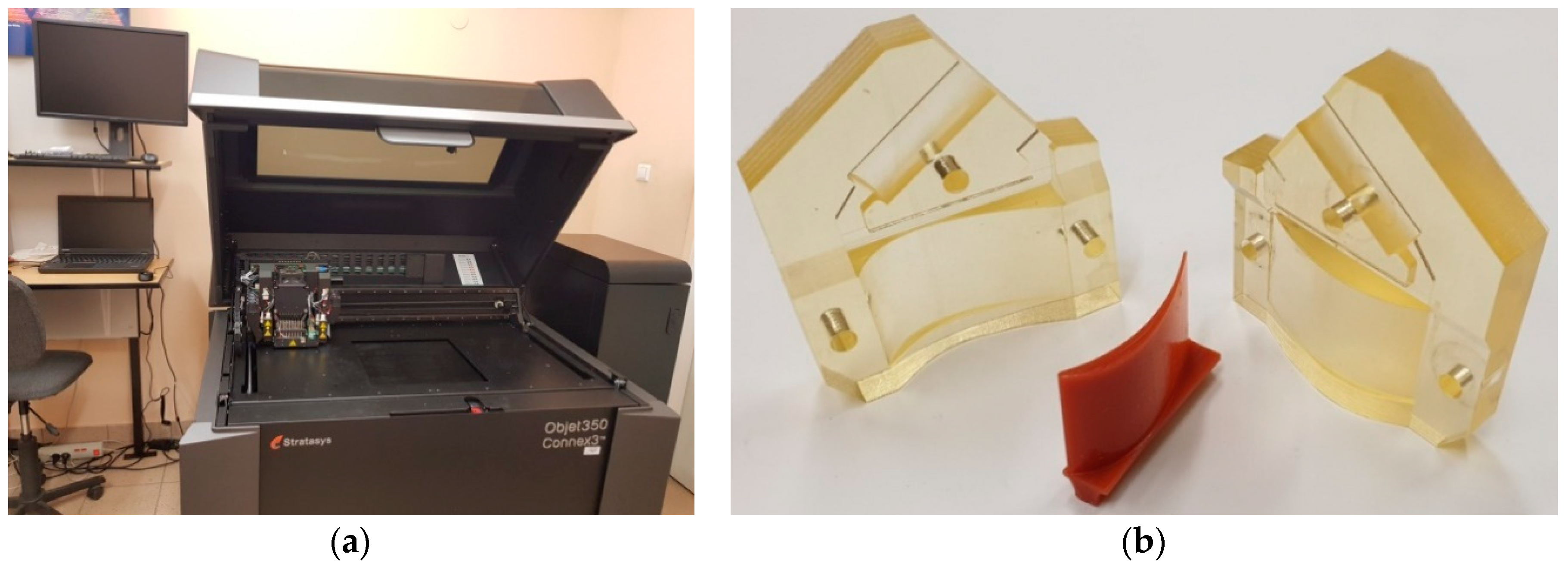
2. Materials and Methods
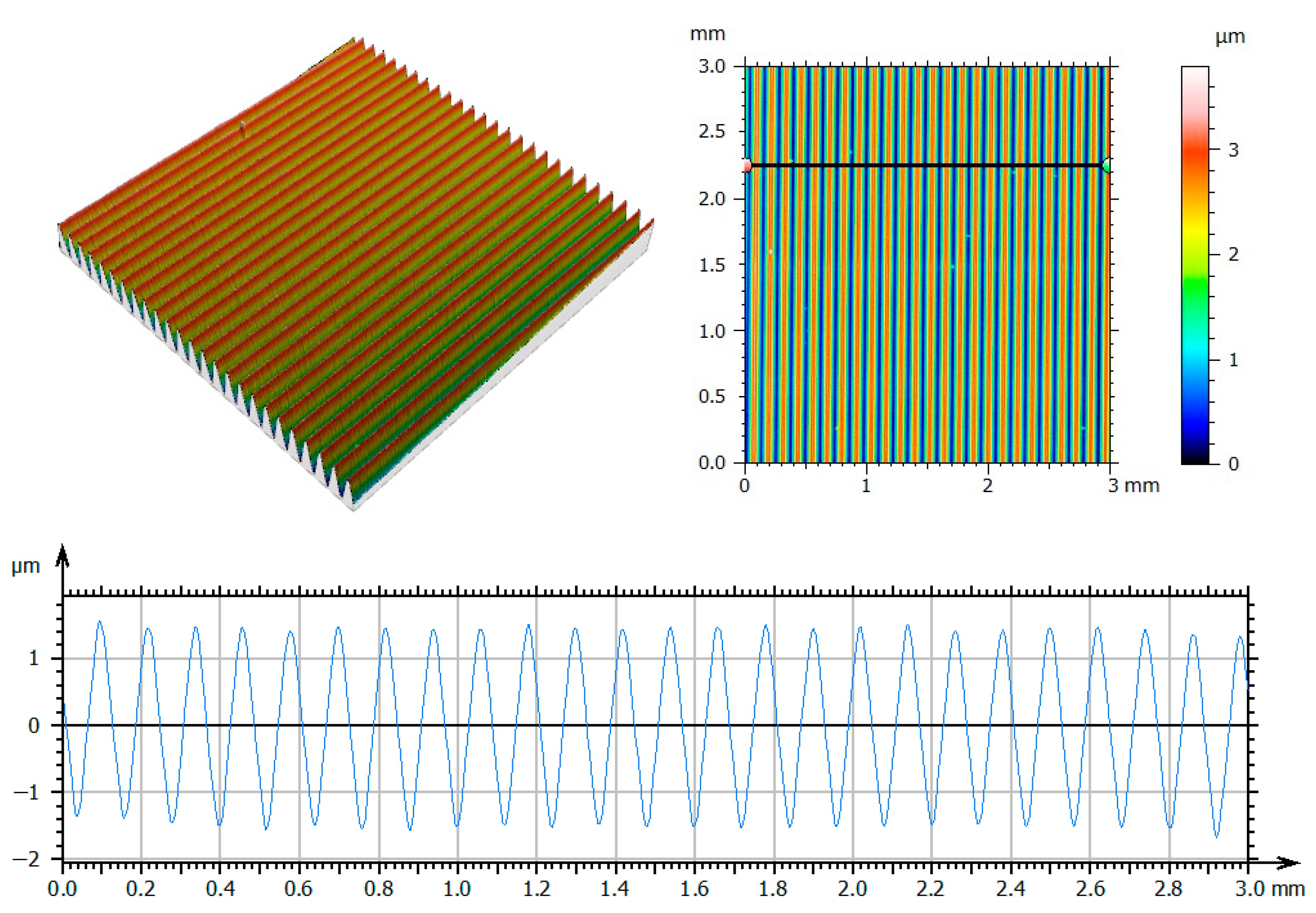
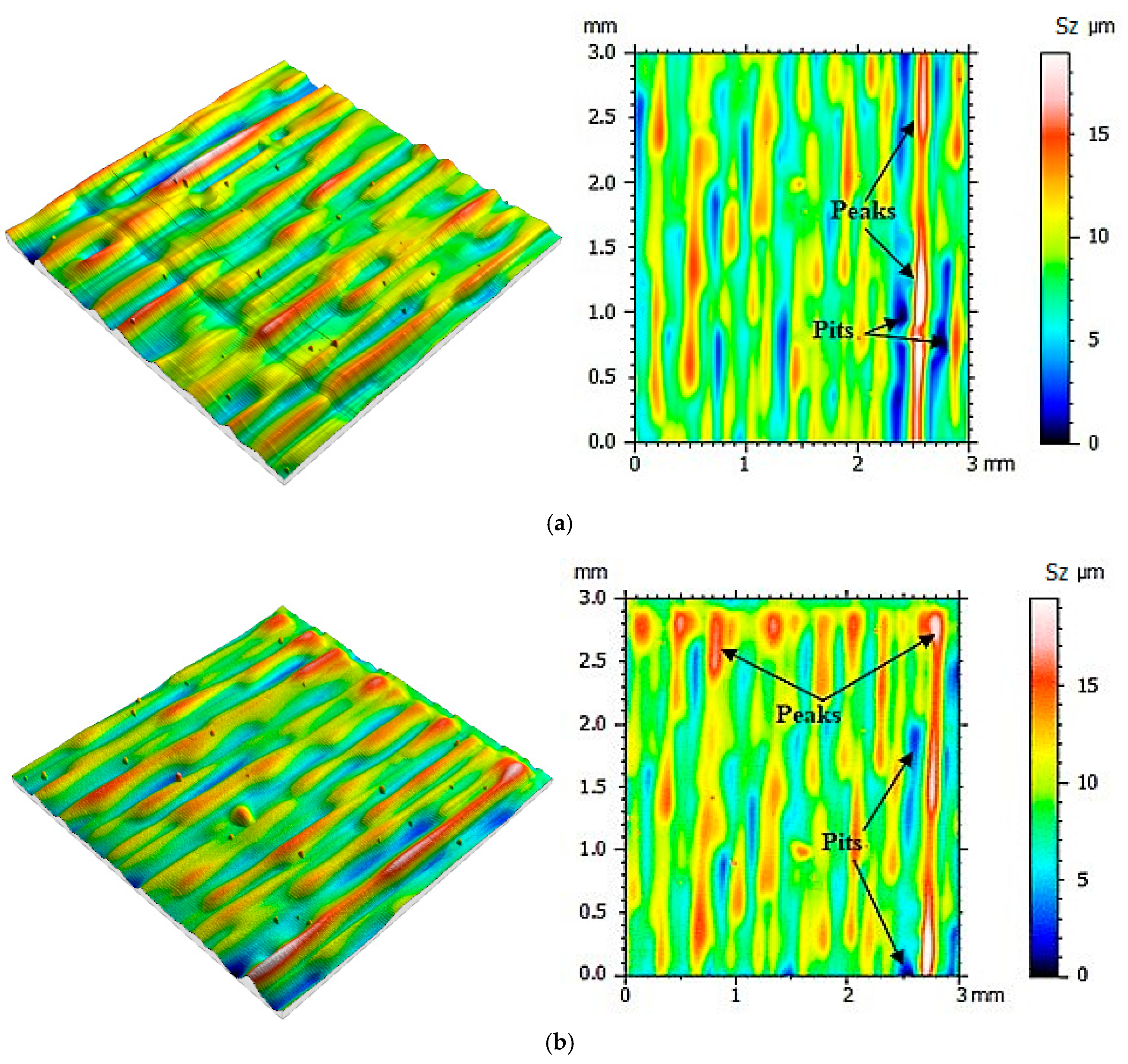
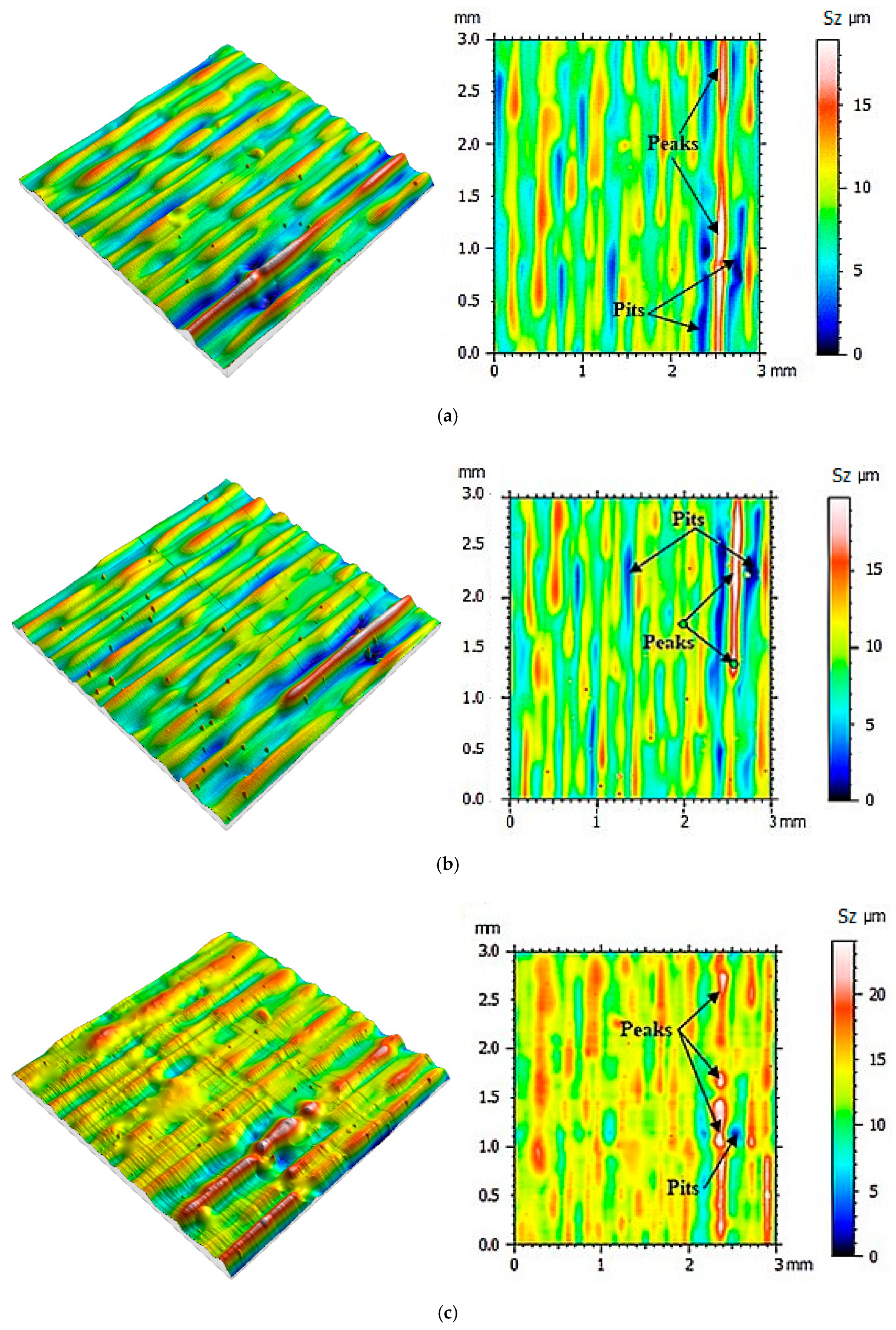
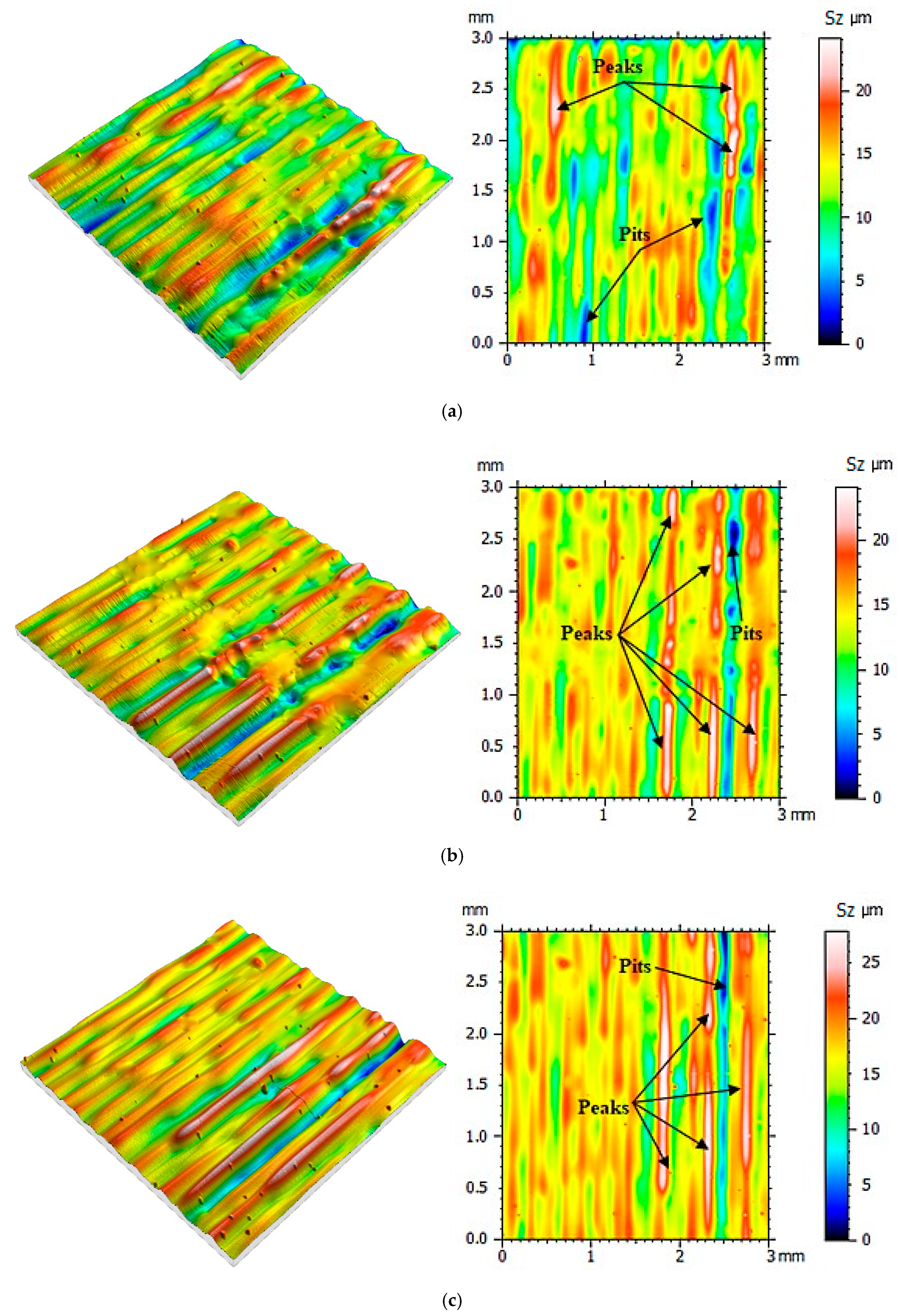
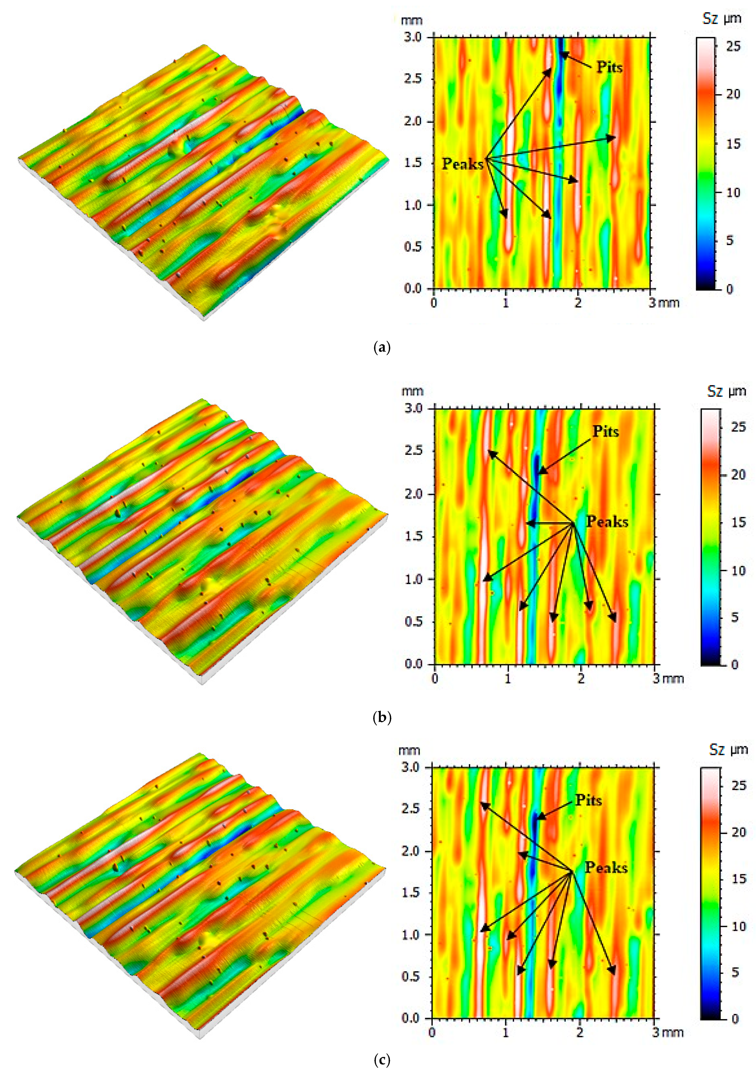
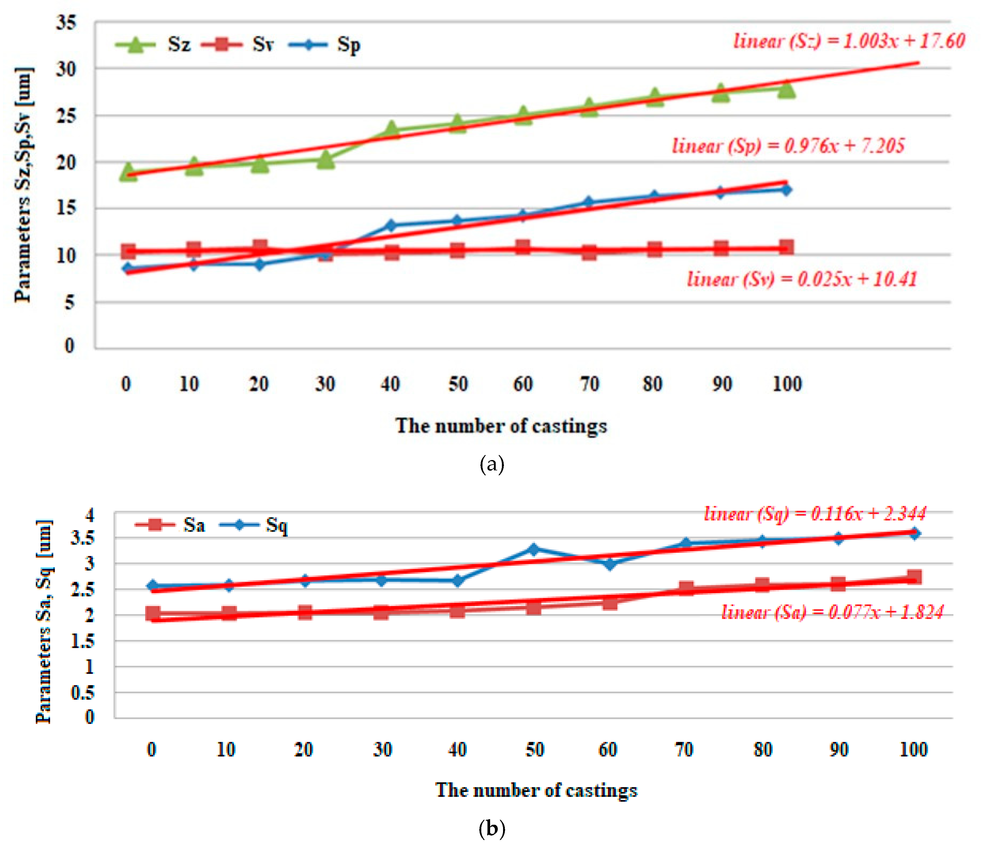
3. Results
4. Discussion
5. Conclusions
Author Contributions
Funding
Conflicts of Interest
References
- Boboulos, M.A. CAD-CAM and Rapid Prototyping Application Evaluation; Bookboon: Copenhagen, Denmark, 2010. [Google Scholar]
- Thompson, M.K.; Moroni, G.; Vaneker, T.; Fadel, G.; Campbell, R.I.; Gibson, I.; Bernard, A.; Schulz, J.; Grafh, P.; Ahujai, B.; et al. Design for Additive Manufacturing: Trends, opportunities, considerations, and constraints. CIRP Ann. 2016, 65, 737–760. [Google Scholar] [CrossRef]
- Gdula, M.; Burek, J.; Żyłka, Ł.; Płodzień, M. Five-axis milling of sculptured surfaces of the turbine blade. Aircr. Eng. Aerosp. Technol. 2018, 90, 146–157. [Google Scholar] [CrossRef]
- Khaliq, M.H.; Gomes, R.; Fernandes, C.; Nóbrega, J.; Carneiro, O.S.; Ferrás, L.L. On the use of high viscosity polymers in the fused filament fabrication process. Rapid Prototyp. J. 2017, 23, 727–735. [Google Scholar] [CrossRef]
- Leal, R.; Barreiros, F.M.; Alves, L.; Romeiro, F.; Vasco, J.C.; Santos, M.; Marto, C. Additive manufacturing tooling for the automotive industry. Int. J. Adv. Manuf. Technol. 2017, 92, 1671–1676. [Google Scholar] [CrossRef]
- Lecklider, T. 3D printing drives automotive innovation. Eval. Eng. 2017, 56, 16–20. [Google Scholar]
- Rokicki, P.; Budzik, G.; Kubiak, K.; Dziubek, T.; Zaborniak, M.; Kozik, B.; Bernaczek, J.; Przeszlowski, L.; Nowotnik, A. The assessment of geometric accuracy of aircraft engine blades with the use of an optical coordinate scanner. Aircr. Eng. Aerosp. Technol. Int. J. 2016, 88, 374–381. [Google Scholar] [CrossRef]
- Ciocca, L.; Mazzoni, S.; Fantini, M.; Persiani, F.; Baldissara, P.; Marchetti, C.; Scotti, R. A CAD/CAM-prototyped anatomical condylar prosthesis connected to a custom-made bone plate to support a fibula free flap. Med. Biol. Eng. Comput. 2012, 50, 743–749. [Google Scholar] [CrossRef]
- Turek, P.; Budzik, G.; Oleksy, M.; Bulanda, K. Polymer materials used in medicine processed by additive echniques. Polimery 2020, 65, 510–515. [Google Scholar] [CrossRef]
- Gisario, A.; Kazarian, M.; Martina, F.; Mehrpouya, M. Metal additive manufacturing in the commercial aviation industry: A review. J. Manuf. Syst. 2019, 53, 124–149. [Google Scholar] [CrossRef]
- Niu, X.; Singh, S.; Garg, A.; Singh, H.; Panda, B.; Peng, X.; Zhang, Q. Review of materials used in laser-aided additive manufacturing processes to produce metallic products. Front. Mech. Eng. 2019, 1–17. [Google Scholar] [CrossRef] [Green Version]
- Kasatkina, M.M.; Kozhinaa, T.D.; Federov, M.M. Additive Technologies in Airplane-Engine Manufacture. Russ. Eng. Res. 2019, 39, 262–267. [Google Scholar] [CrossRef]
- Tuttle, R.B. Foundry Engineering: The Metallurgy and Design of Castings; Create Space: Scotts Valley, CA, USA, 2012. [Google Scholar]
- Upadhyay, M.; Sivarupan, T.; El Mansori, M. 3D printing for rapid sand casting—A review. J. Manuf. Process. 2017, 29, 211–220. [Google Scholar] [CrossRef] [Green Version]
- Dalquist, S.; Gutowski, T. Life Cycle Analysis of Conventional Manufacturing Techniques: Sand Casting. ASME Int. Mech. Eng. Congr. Expo. 2004, 47136, 631–641. [Google Scholar] [CrossRef]
- Jiang, W.; Fan, Z.; Liu, D.; Liao, D.; Dong, X.; Zong, X. Correlation of microstructure with mechanical properties and fracture behavior of A356-T6 aluminum alloy fabricated by expendable pattern shell casting with vacuum and low-pressure, gravity casting and lost foam casting. Mater. Sci. Eng. A 2013, 560, 396–403. [Google Scholar] [CrossRef]
- Singh, R.; Verma, M. Investigations for reducing wall thickness of aluminium shell casting using three dimensional printing. J. Achiev. Mater. Manuf. Eng. 2008, 31, 565–569. [Google Scholar]
- Kaplas, M.; Singh, R. Experimental investigations for reducing wall thickness in zinc shell casting using three-dimensional printing. Proc. Inst. Mech. Eng. Part C: J. Mech. Eng. Sci. 2008, 222, 2427–2431. [Google Scholar] [CrossRef]
- Kim, K.D.; Yang, D.Y.; Jeong, J.H. Plaster casting process for prototyping of die casting based on rapid tooling. Int. J. Adv. Manuf. Technol. 2006, 28, 923–929. [Google Scholar] [CrossRef]
- Wu, H.; Li, D.; Chen, X.; Sun, B.; Xu, D. Rapid casting of turbine blades with abnormal film cooling holes using integral ceramic casting molds. Int. J. Adv. Manuf. Technol. 2010, 50, 13–19. [Google Scholar] [CrossRef]
- Aveson, J.W.; Tennant, P.A.; Foss, B.J.; Shollock, B.A.; Stone, H.J.; D’Souza, N. On the origin of sliver defects in single crystal investment castings. Acta Mater. 2013, 61, 5162–5171. [Google Scholar] [CrossRef]
- Konrad, C.H.; Brunner, M.; Kyrgyzbaev, K.; Völkl, R.; Glatzel, U. Determination of heat transfer coefficient and ceramic mold material parameters for alloy IN738LC investment castings. J. Mater. Process. Technol. 2011, 211, 181–186. [Google Scholar] [CrossRef]
- Klobčar, D.; Tušek, J.; Taljat, B. Thermal fatigue of materials for die-casting tooling. Mater. Sci. Eng. A 2008, 472, 198–207. [Google Scholar] [CrossRef]
- Niu, X.P.; Hu, B.H.; Pinwill, I.; Li, H. Vacuum assisted high pressure die casting of aluminium alloys. J. Mater. Process. Technol. 2000, 105, 119–127. [Google Scholar] [CrossRef]
- Chirita, G.; Soares, D.; Silva, F.S. Advantages of the centrifugal casting technique for the production of structural components with Al–Si alloys. Mater. Des. 2008, 29, 20–27. [Google Scholar] [CrossRef]
- Zhao, D.-Y.; Huang, Z.-P.; Wang, M.-J.; Wang, T.; Jin, Y. Vacuum casting replication of micro-riblets on shark skin for drag-reducing applications. J. Mater. Process. Technol. 2012, 212, 198–202. [Google Scholar] [CrossRef]
- Tang, Y.; Tan, W.K.; Fuh, J.Y.H.; Loh, H.T.; Wong, Y.S.; Thian, S.C.H.; Lu, L. Micro-mould fabrication for a micro-gear via vacuum casting. J. Mater. Process. Technol. 2007, 192, 334–339. [Google Scholar] [CrossRef]
- Ma, D. Novel Casting Processes for Single-Crystal Turbine Blades of Superalloys. Front. Mech. Eng. 2018, 13, 3–16. [Google Scholar] [CrossRef] [Green Version]
- Wee, S.; Do, J.; Kim, K.; Lee, C.; Seok, C.; Choi, B.-G.; Choi, Y.; Kim, W. Review on Mechanical Thermal Properties of Superalloys and Thermal Barrier Coating Used in Gas Turbines. Appl. Sci. 2020, 10, 5476. [Google Scholar] [CrossRef]
- Singh, D.; Singh, R.; Boparai, K.S. Development and surface improvement of FDM pattern based investment casting of biomedical implants: A state of art review. J. Manuf. Process. 2018, 31, 80–95. [Google Scholar] [CrossRef]
- Aziz, M.N.; Munyensanga, P.; Widyanto, S.A. Application of lost wax casting for manufacturing of orthopedic screw: A review. Procedia CIRP 2018, 78, 149–154. [Google Scholar] [CrossRef]
- Wang, J.; Sama, S.R.; Lynch, P.C.; Manogharan, G. Design and Topology Optimization of 3D-Printed Wax Patterns for Rapid Investment Casting. Procedia Manuf. 2019, 34, 683–694. [Google Scholar] [CrossRef]
- Chica, E.; Agudelo, S.; Sierra, N. Lost Wax Casting Process of the Runner of a Propeller Turbine for Small Hydroelectric Power Plants. Renew. Energy 2013, 60, 739–745. [Google Scholar] [CrossRef]
- Pattnaik, S.; Karunakar, D.B.; Jha, P.K. Developments in Investment Casting Process—A review. J. Mater. Process. Technol. 2012, 11, 2332–2348. [Google Scholar] [CrossRef]
- Budzik, G.; Kubiak, K.; Matysiak, H.; Cygan, R.; Tutak, M. Hybrid method for rapid prototyping of core models of aircraft engine blades. J. Kones 2012, 19, 77–82. [Google Scholar] [CrossRef]
- Roskosz, S.; Szeliga, D.; Cygan, R.; Rokicki, P. Investment Casting Design and Processing for Drone’s Micro-Engine Turbine Rotor Manufacturing. In Solid State Phenomena; Trans Tech Publications Ltd.: Pfaffikon, Switzerland, 2016; pp. 189–192. [Google Scholar] [CrossRef]
- Hanemann, T.; Bauer, W.; Knitter, R.; Woias, P. Rapid Prototyping and Rapid Tooling Techniques for the Manufacturing of Silicon, Polymer, Metal and Ceramic Microdevices. In MEMS/NEMS; Springer: Boston, MA, USA, 2006; pp. 801–869. [Google Scholar] [CrossRef]
- Wu, H.; Li, D.; Guo, N. Fabrication of Integral Ceramic Mold for Investment Casting of Hollow Turbine Blade Based on Stereolithography. Rapid Prototyp. J. 2009, 15, 232–237. [Google Scholar] [CrossRef]
- Rokicki, P.; Budzik, G.; Kubiak, K.; Bernaczek, J.; Dziubek, T.; Magniszewski, M.; Nowotnik, A.; Sieniawski, J. Rapid prototyping in manufacturing of core models of aircraft engine blades. Aircr. Eng. Aerosp. Technol. Int. J. 2014, 86, 323–327. [Google Scholar] [CrossRef]
- Cheah, C.M.; Chua, C.K.; Lee, C.W.; Feng, C.; Totong, K. Rapid Prototyping and Tooling Techniques: A Review of Applications for Rapid Investment Casting. Int. J. Adv. Manuf. Technol. 2005, 25, 308–320. [Google Scholar] [CrossRef]
- Thomas, P.A.; Aahlada, P.K.; Kiran, N.S.; Ivvala, J. A Review on Transition in the Manufacturing of Mechanical Components from Conventional Techniques to Rapid Casting Using Rapid Prototyping. Mater. Today Proc. 2018, 5, 11990–12002. [Google Scholar] [CrossRef]
- Budzik, G.; Matysiak, H.; Cygan, R.; Bąk, S.; Cygnar, M. Rapid Prototyping Process of Monocrystal Aircraft Engine Blades. J. Kones 2010, 17, 81–86. [Google Scholar]
- Rahmati, S.; Akbari, J.; Barati, E. Dimensional accuracy analysis of wax patterns created by RTV silicone rubber molding using the Taguchi approach. Rapid Prototyp. J. 2007, 13, 115–122. [Google Scholar] [CrossRef]
- Kuo, C.-C.; Wu, M.-X. Evaluation of Service Life of Silicone Rubber Molds Using Vacuum Casting. Int. J. Adv. Manuf. Technol. 2017, 90, 3775–3781. [Google Scholar] [CrossRef]
- Pham, D.; Dimov, S.S. Rapid Manufacturing: The Technologies and Applications of Rapid Prototyping and Rapid Tooling; Springer Science & Business Media: Berlin, Germany, 2012. [Google Scholar]
- Pessard, E.; Mognol, P.; Hascoët, J.Y.; Gerometta, C. Complex Cast Parts with Rapid Tooling: Rapid Manufacturing Point of View. Int. J. Adv. Manuf. Technol. 2008, 39, 898–904. [Google Scholar] [CrossRef]
- Gibson, I.; Rosen, D.W.; Stucker, B. Additive Manufacturing Technologies; Springer: New York, NY, USA, 2014. [Google Scholar]
- Poodts, E.; Minak, G.; Poodts, E.; Minak, G. Application of Rapid Tooling for the Production of Moulds Suitable for Autoclave Forming of CFRP. Rapid Prototyp. J. 2013, 19, 327–336. [Google Scholar] [CrossRef]
- Volpato, N.; Solis, D.M.; Costa, C.A. An Analysis of Digital ABS as a Rapid Tooling Material for Polymer Injection Moulding. Int. J. Mater. Prod. Technol. 2016, 52, 3–16. [Google Scholar] [CrossRef]
- Bagalkot, A.; Pons, D.; Clucas, D.; Symons, D. A methodology for setting the injection moulding process parameters for polymer rapid tooling inserts. Rapid Prototyp. J. 2019, 25, 1493–1505. [Google Scholar] [CrossRef]
- Kampker, A.; Triebs, J.; Kawollek, S.; Ayvazand, P.; Beyer, T. Direct Polymer Additive Tooling–effect of Additive Manufactured Polymer Tools on Partmaterial Properties for Injection Moulding. Rapid Prototyp. J. 2019, 25, 1575–1584. [Google Scholar] [CrossRef]
- Lee, K.-Y.; Cho, J.-W.; Chang, N.-Y.; Chae, J.-M.; Kang, K.-H.; Kim, S.-C.; Cho, J.-H. Accuracy of three-dimensional printing for manufacturing replica teeth. Korean J. Orthod. 2015, 45, 217–225. [Google Scholar] [CrossRef] [Green Version]
- Kechagias, J.; Stavropoulos, P.; Koutsomichalis, A.; Ntintakis, I.; Vaxevanidis, N. Dimensional accuracy optimization of prototypes produced by PolyJet direct 3D printing technology. Adv. Eng. Mech. Mater. 2014, 61–65. Available online: http://inase.org/library/2014/santorini/bypaper/MECHANICS/MECHANICS-07.pdf (accessed on 10 December 2020).
- Chen, L.; Lin, W.-S.; Polido, W.D.; Eckert, G.J.; Morton, D. Accuracy, Reproducibility, and Dimensional Stability of Additively Manufactured Surgical Templates. J. Prosthet. Dent. 2019, 122, 309–314. [Google Scholar] [CrossRef]
- Budzik, G.; Turek, P.; Dziubek, T.; Gdula, M. Elaboration of the Measuring procedure Facilitating Precision assessment of the Geometry of Mandible Anatomical Model manufactured Using Additive Methods. Meas. Control 2020, 53, 181–191. [Google Scholar] [CrossRef]
- Shim, J.S.; Kim, J.-E.; Jeong, S.H.; Choi, Y.J.; Ryu, J.J. Printing accuracy, mechanical properties, surface characteristics, and microbial adhesion of 3D-printed resins with various printing orientations. J. Prosthet. Dent. 2020, 124, 468–475. [Google Scholar] [CrossRef]
- Gavariev, R.V.; Savin, I.A. Improvement of Surface Quality of Casting Produced by Casting under Pressure. In Solid State Phenomena; Trans Tech Publications Ltd.: Pfaffikon, Switzerland, 2017; Volume 265, pp. 988–993. [Google Scholar] [CrossRef]
- Chhabra, M.; Singh, R. Obtaining desired surface roughness of castings produced using ZCast direct metal casting process through Taguchi’s experimental approach. Rapid Prototyp. J. 2012, 18, 458–471. [Google Scholar] [CrossRef]
- Józwik, J. Analysis of the Effect of Trochoidal Milling on the Surface Roughness of Aluminium Alloy safter Milling. Manuf. Technol. 2019, 19, 772–779. [Google Scholar] [CrossRef]
- Leach, R. Optical Measurement of Surface Topography; Springer: Berlin, Germany, 2011. [Google Scholar]
- Pawlus, P.; Reizer, R.; Wieczorowski, M. Comparison of Results of Surface Texture Measurement Obtained with Stylus Methods and Optical Methods. Metrol. Meas. Syst. 2018, 25, 589–602. [Google Scholar]
- Mah, J.; Samson, C.; McKinnon, S.D.; Thibodeau, D. 3D laser imaging for surface roughness analysis. Int. J. Rock Mech. Min. Sci. 2013, 58, 111–117. [Google Scholar] [CrossRef]
- Li, X.Q.; Lu, Z.X.; Zhao, L.Y.; Li, Z.H.; Guo, B.; Bai, X.F. The Measurement of Three-Dimensional Road Roughness Based on Laser Triangulation. In Advanced Materials Research; Trans Tech Publications Ltd.: Pfaffikon, Switzerland, 2012; pp. 812–816. [Google Scholar] [CrossRef]
- Wyant, J.C. White light interferometry. In Proceedings of the International Society for Optics and Photonics, Orlando, FL, USA, 9 July 2002; pp. 98–107. [Google Scholar] [CrossRef]
- Pavliček, P.; Hýbl, O. White-light interferometry on rough surfaces--measurement uncertainty caused by surface roughness. Appl. Opt. 2008, 47, 2941–2949. [Google Scholar] [CrossRef]
- Bezak, T.; Kusy, M.; Elias, M.; Kopcek, M.; Kebisek, M.; Spendla, L. Identification of Surface Topography Scanned by Laser Scanning Confocal Microscope. Appl. Mech. Mater. 2014, 693, 329–334. [Google Scholar] [CrossRef]
- Fu, S.; Cheng, F.; Tjahjowidodo, T.; Zhou, Y.; Butler, D. A Non-Contact Measuring System for In-Situ Surface Characterization Based on Laser Confocal Microscopy. Sensors 2018, 18, 2657. [Google Scholar] [CrossRef] [Green Version]
- Wang, X.; Shi, T.; Liao, G.; Zhang, Y.; Hong, Y.; Chen, K. Using Wavelet Packet Transform for Surface Roughness Evaluation and Texture Extraction. Sensors 2017, 17, 933. [Google Scholar] [CrossRef]
- Danzl, R.; Helmli, F.; Scherer, S. Focus Variation—A Robust Technology for High Resolution Optical 3D Surface Metrology. Stroj. Vestn. J. Mech. Eng. 2011, 57, 245–256. [Google Scholar] [CrossRef] [Green Version]
- Helmli, F. Focus Variation Instruments. In Optical Measurement of Surface Topography; Springer: Berlin/Heidelberg, Germany, 2011; pp. 131–166. [Google Scholar] [CrossRef]
- Kapłonek, W.; Nadolny, K.; Królczyk, G.M. The Use of Focus-Variation Microscopy for the Assessment of Active Surfaces of a New Generation of Coated Abrasive Tools. Meas. Sci. Rev. 2016, 16, 42–53. [Google Scholar] [CrossRef] [Green Version]
- Macdonald, D.A. The application of focus variation microscopy for lithic use-wear quantification. J. Archaeol. Sci. 2014, 48, 26–33. [Google Scholar] [CrossRef]
- Vorburger, T.V.; Rhee, H.G.; Renegar, T.B.; Song, J.F.; Zheng, A. Comparison of optical and stylus methods for measurement of surface texture. Int. J. Adv. Manuf. Technol. 2007, 33, 110–118. [Google Scholar] [CrossRef]
- Kozior, T.; Adamczak, S.; Kozior, T.; Adamczak, S. Amplitude Surface Texture Parameters of Models Manufactured by FDM Technology. In The International Symposium for Production Research; Springer: Cham, Switzerland, 2018; pp. 208–217. [Google Scholar] [CrossRef]
- Fox, J.C.; Moylan, S.P.; Lane, B.M. Effect of Process Parameters on the Surface Roughness of Overhanging Structures in Laser Powder Bed Fusion Additive Manufacturing. Procedia CIRP 2016, 45, 131–134. [Google Scholar] [CrossRef] [Green Version]
- Jamshidinia, M.; Kovacevic, R. The influence of heat accumulation on the surface roughness in powder-bed additive manufacturing. Surf. Topogr. Metrol. Prop. 2015, 3, 014003. [Google Scholar] [CrossRef]
- Turner, B.N.; Gold, S.A. A review of melt extrusion additive manufacturing processes: II. Materials, dimensional accuracy, and surface roughness. Rapid Prototyp. J. 2015, 21, 250–261. [Google Scholar] [CrossRef]
- Hamoud, M. Surface Roughness Justificationin Additive Manufacturing. In The International Conference on Applied Mechanics and Mechanical Engineering; Military Technical College: Cairo, Egypt, 2018; pp. 1–11. [Google Scholar] [CrossRef]
- Udroiu, R.; Mihail, L.A. Experimental determination of surface roughness of parts obtained by rapid prototyping. CSECS 2009, 9, 283–286. [Google Scholar]
- Iftikhar, A.; Khan, M.; Alam, K.; Imran Jaffery, S.H.; Ali, L.; Ayaz, Y.; Khan, A. Turbine Blade Manufacturing Through Rapid Tooling (RT) Process and Its Quality Inspection. Mater. Manuf. Process. 2013, 28, 534–538. [Google Scholar] [CrossRef]
- Dunnea, P.; Soeb, S.P.; Byrnea, G.; Venusc, A.; Wheatleyb, A.R. Some Demands on Rapid Prototypes Used as Master Patterns in Rapid Tooling for Injection moulding. J. Mater. Process. Technol. 2004, 150, 201–207. [Google Scholar] [CrossRef]
- Pal, D.; Ravi, B. Rapid Tooling Route Selection and Evaluation for Sand and Investment Casting. Virtual Phys. Prototyp. 2007, 2, 197–207. [Google Scholar] [CrossRef]
- Chohan, J.S.; Singh, R.; Boparai, K.S. Thermal and surface characterization of ABS replicas made by FDM for rapid tooling applications Rapid Prototyp. J. 2018, 24, 28–36. [Google Scholar] [CrossRef]
- Jiao, Z.Y.; Liu, X.Y.; Zhang, M.Y. Finite Element Analysis on Inputting Cantilever of Bucket-Wheel Reclaimer Based on CATIA and ANSYS. In Applied Mechanics and Materials; Trans Tech Publications Ltd.: Pfaffikon, Switzerland, 2014; pp. 194–199. [Google Scholar] [CrossRef]
- MohdFuad, N.; Carve, M.; Kaslin, J.; Wlodkowic, D. Characterization of 3D-printed moulds for soft lithography of millifluidic devices. Micromachines 2018, 9, 116. [Google Scholar] [CrossRef] [PubMed] [Green Version]
- Hoskin Scientifique. Available online: http://www.hoskinscientifique.com (accessed on 1 January 2004).
- Hoskin Scientifique. Available online: http://www.hoskinscientifique.com/uploadpdf/Instrumentation/Taylor%20Hobson (accessed on 6 July 2006).
- Hansen, J. Assessing the Tribological Interface of Mechanical Parts; Digital Surf.: Besançon, France, 2020; pp. 6–7. [Google Scholar]


| Casting Method | Advantages | Disadvantages | |
|---|---|---|---|
| Expendable—Mold is Made of Various Types of Binders Bonding Agents (Sand, Plaster, Ceramics) | Sand casting—characterized by using sand as the mold material [14,15] | Tooling cost are low; Relative easy process; Sand in most cases can be reused | Single use of mold; Poor surface finishing; Limited design freedom |
| Shell casting—the mold is a thin shell of sand held together by resin binder [16,17,18] | Smoother cavity surface; Good dimensional accuracy; Machining often not required | Difficult justify for small quantities; More expensive metal pattern | |
| Plaster casting—similar to sand casting except that mold is made of plaster of Paris material [19] | Low tooling cost; Good dimensional accuracy and surface finishing | It can only be used with lower melting temperature; | |
| Ceramic casting—similar to plaster mold casting except that mold is made of ceramic material [20] | Complex shapes can be produced; High homogeneous slurries can be produced | Lower dimensional accuracy; Low production rate | |
| Investment casting (Lost—wax)—a mold is formed around a pattern of wax or similar material which is then removed by melting [21,22] | Good dimensional accuracy and surface finishing; Can be automated; Complex shapes with fine details can be made | Less strength than die cast parts; More steps are involved in production | |
| Permanent—mold is made of metal | Die casting—molten metal is injected into mold cavity under high pressure [23,24] | Economical for large production; Good dimensional accuracy and surface finishing | Generally limited to metals; Part geometry must allow removal for die cavity |
| Centrifugal casting—method of producing casting by pouring the molten metal into rapidly rotating mold [25] | Good surface finishing and accuracy; Low equipment cost; Can form very large parts | Limited to the cylindrical parts; Long lead time possible |
| Standard Value [μm] | Mean Deviation [μm] | Standard Deviation (s) [μm] | Standard Deviation of the Mean Value (Sr) [μm] | |
|---|---|---|---|---|
| Ra | 0.910 | 0.878 | 0.003 | 0.001 |
| Rz | 3.100 | 3.054 | 0.023 | 0.010 |
| Sa | 0.900 | 0.878 | 0.004 | 0.002 |
| Sz | 3.100 | 3.185 | 0.028 | 0.016 |
| Sq [μm] | Ssk | Sku | Sv [μm] | Sp [μm] | Sz [μm] | Sa [μm] | |
|---|---|---|---|---|---|---|---|
| Without casting | 2.578 | 0,287 | 3.260 | 10.440 | 8.590 | 18.980 | 2.038 |
| After 10 | 2.590 | 0.372 | 3.235 | 10.600 | 9.001 | 19.600 | 2.044 |
| After 20 | 2.680 | 0.320 | 3.551 | 10.880 | 9.012 | 19.890 | 2.056 |
| After 30 | 2.692 | 0.267 | 3.948 | 10.190 | 10.140 | 20.340 | 2.062 |
| After 40 | 2.681 | 0.158 | 3.886 | 10.300 | 13.190 | 23.490 | 2.088 |
| After 50 | 3.286 | 0.131 | 3.170 | 10.500 | 13.690 | 24.190 | 2.157 |
| After 60 | 3.001 | 0.290 | 4.194 | 10.830 | 14.240 | 25.070 | 2.251 |
| After 70 | 3.398 | 0.329 | 4.571 | 10.250 | 15.690 | 25.940 | 2.516 |
| After 80 | 3.443 | 0.329 | 3.865 | 10.680 | 16.330 | 27.020 | 2.596 |
| After 90 | 3.502 | 0.351 | 3.857 | 10.750 | 16.740 | 27.490 | 2.611 |
| After 100 | 3.599 | 0.297 | 3.760 | 10.870 | 17.050 | 27.920 | 2.746 |
Publisher’s Note: MDPI stays neutral with regard to jurisdictional claims in published maps and institutional affiliations. |
© 2020 by the authors. Licensee MDPI, Basel, Switzerland. This article is an open access article distributed under the terms and conditions of the Creative Commons Attribution (CC BY) license (http://creativecommons.org/licenses/by/4.0/).
Share and Cite
Turek, P.; Budzik, G.; Sęp, J.; Oleksy, M.; Józwik, J.; Przeszłowski, Ł.; Paszkiewicz, A.; Kochmański, Ł.; Żelechowski, D. An Analysis of the Casting Polymer Mold Wear Manufactured Using PolyJet Method Based on the Measurement of the Surface Topography. Polymers 2020, 12, 3029. https://doi.org/10.3390/polym12123029
Turek P, Budzik G, Sęp J, Oleksy M, Józwik J, Przeszłowski Ł, Paszkiewicz A, Kochmański Ł, Żelechowski D. An Analysis of the Casting Polymer Mold Wear Manufactured Using PolyJet Method Based on the Measurement of the Surface Topography. Polymers. 2020; 12(12):3029. https://doi.org/10.3390/polym12123029
Chicago/Turabian StyleTurek, Paweł, Grzegorz Budzik, Jarosław Sęp, Mariusz Oleksy, Jerzy Józwik, Łukasz Przeszłowski, Andrzej Paszkiewicz, Łukasz Kochmański, and Damian Żelechowski. 2020. "An Analysis of the Casting Polymer Mold Wear Manufactured Using PolyJet Method Based on the Measurement of the Surface Topography" Polymers 12, no. 12: 3029. https://doi.org/10.3390/polym12123029
APA StyleTurek, P., Budzik, G., Sęp, J., Oleksy, M., Józwik, J., Przeszłowski, Ł., Paszkiewicz, A., Kochmański, Ł., & Żelechowski, D. (2020). An Analysis of the Casting Polymer Mold Wear Manufactured Using PolyJet Method Based on the Measurement of the Surface Topography. Polymers, 12(12), 3029. https://doi.org/10.3390/polym12123029