Polyurethane-Carbon Nanotubes Composite Dual Band Antenna for Wearable Applications


 ,
, 
Abstract
1. Introduction
2. Materials and Methods
2.1. Materials
2.2. Sample Preparation
2.3. Methods
3. Results
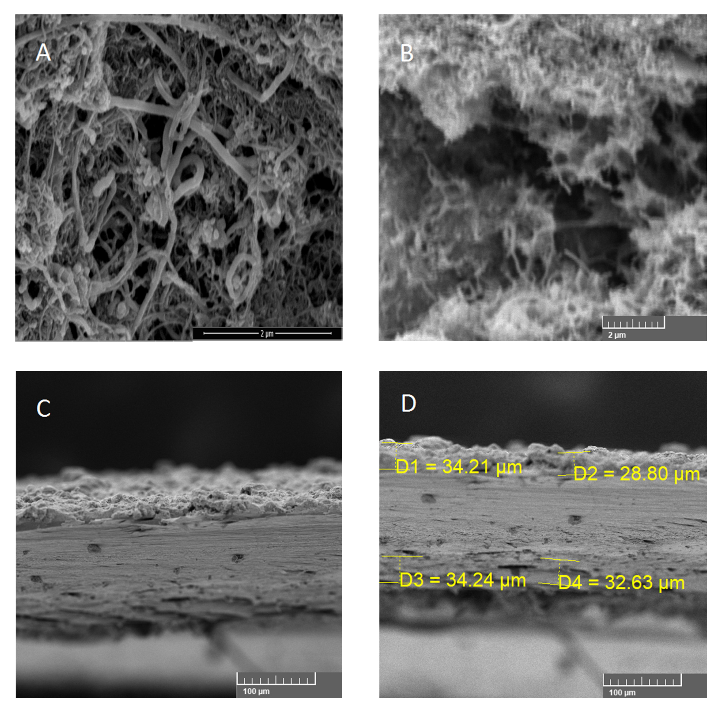
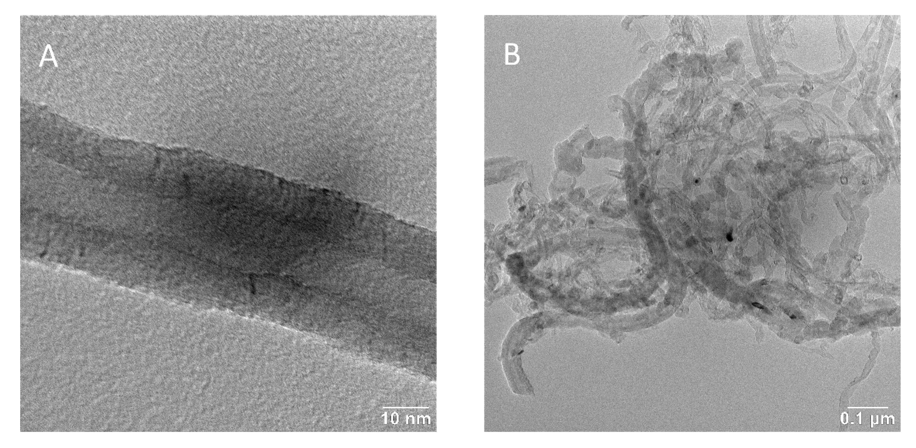
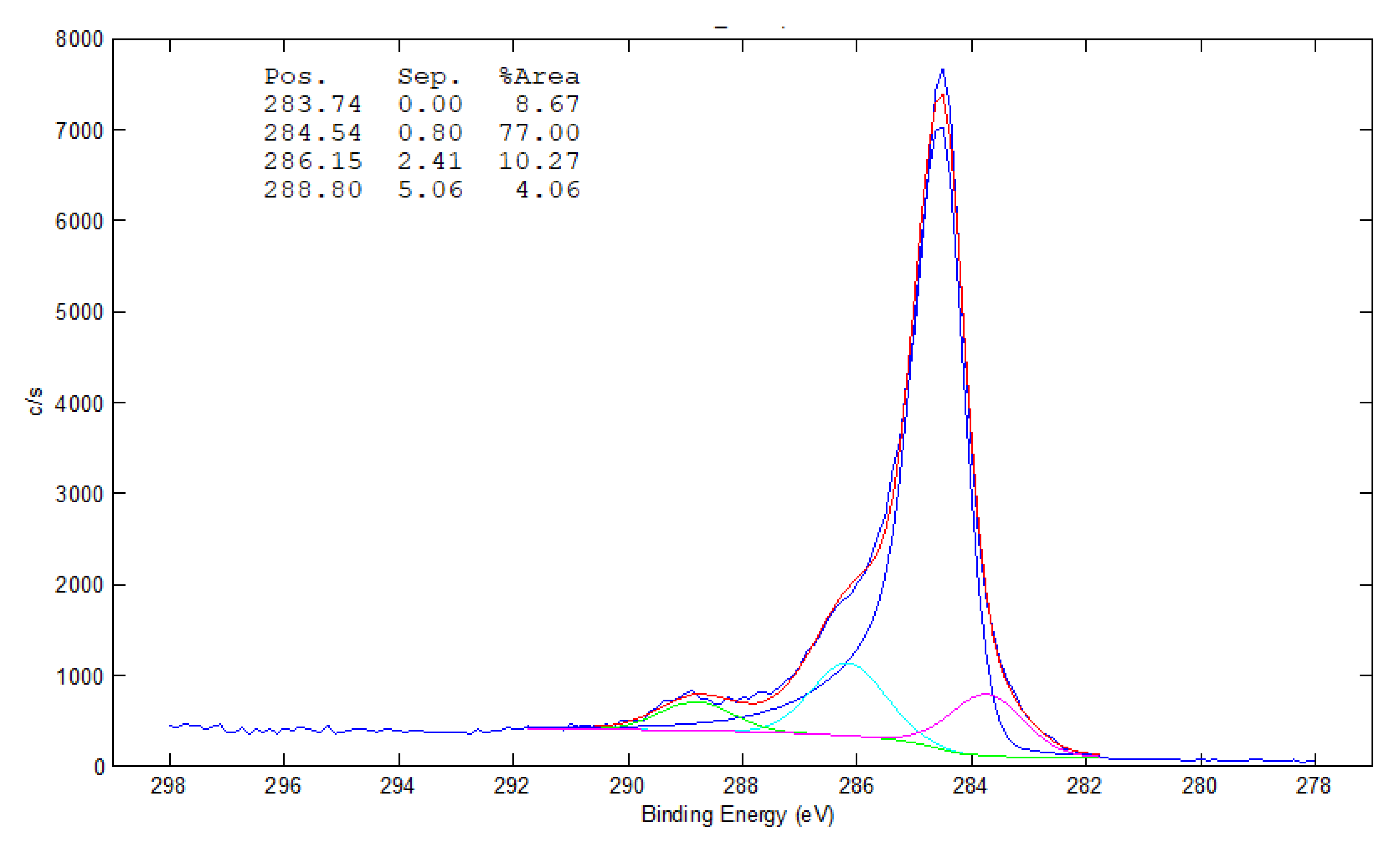
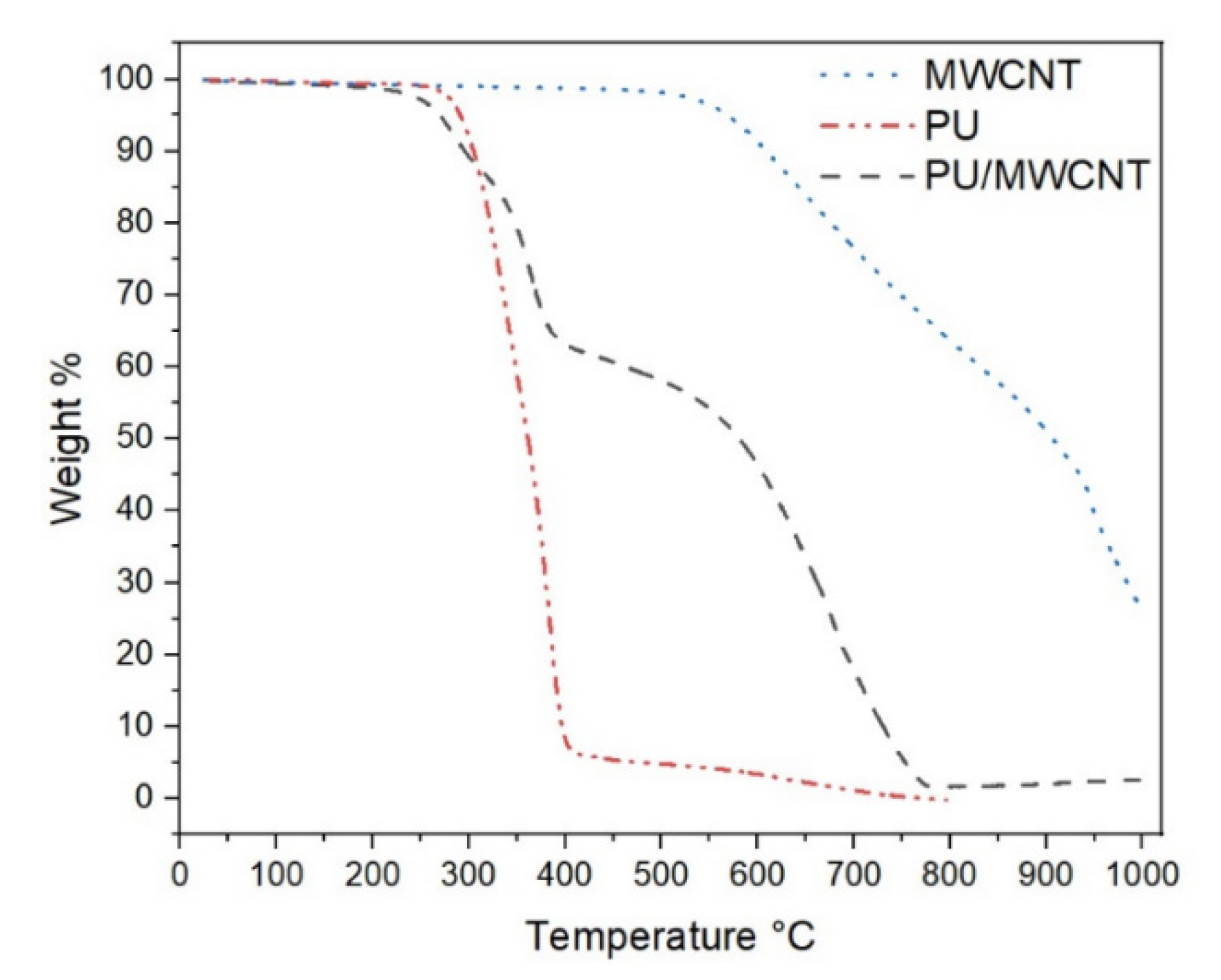
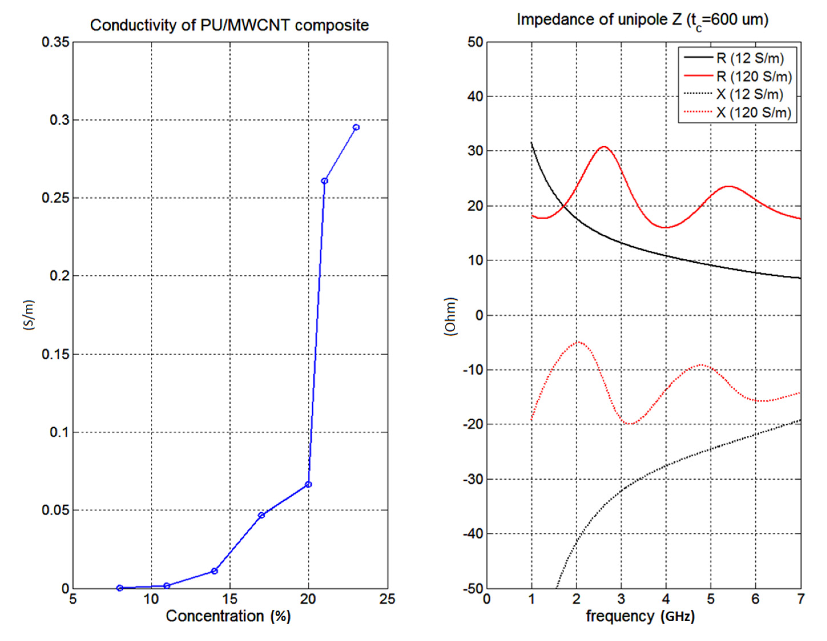
3.1. Composite Material
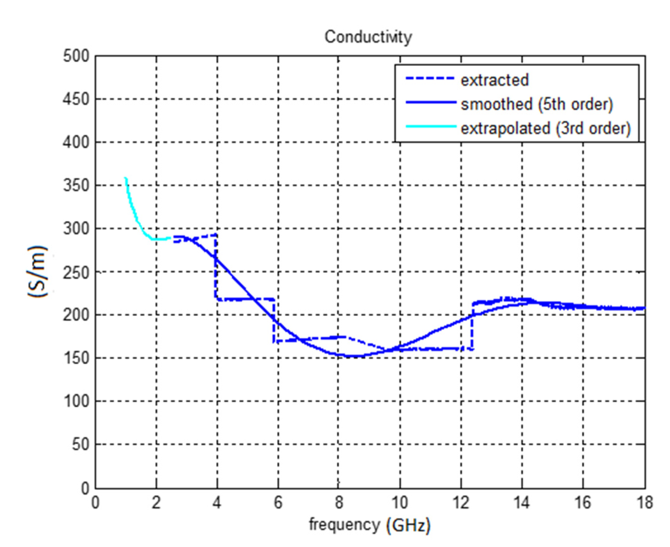
3.2. Electrical Characterization
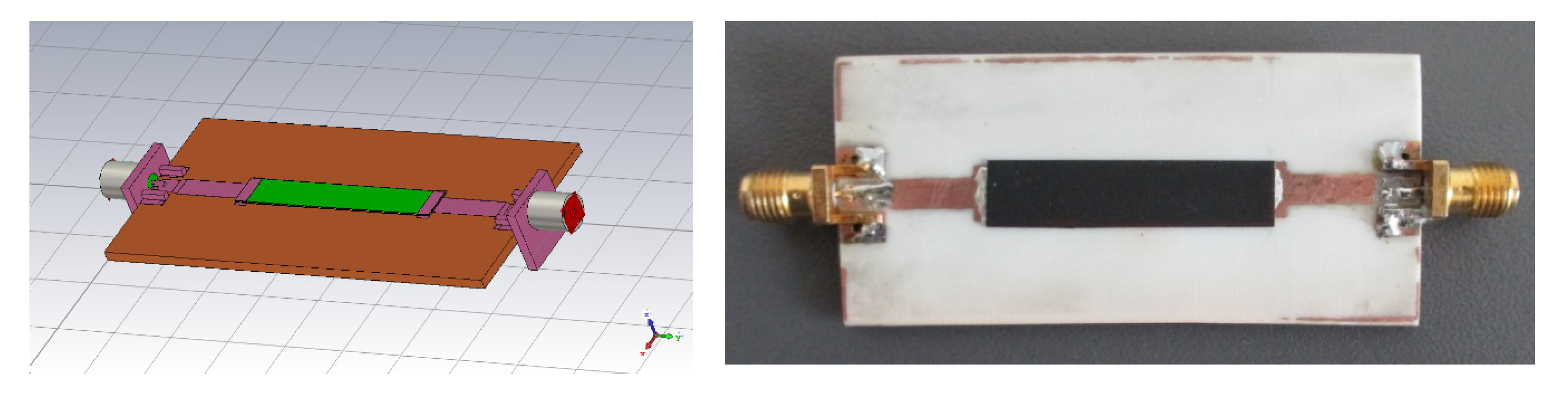
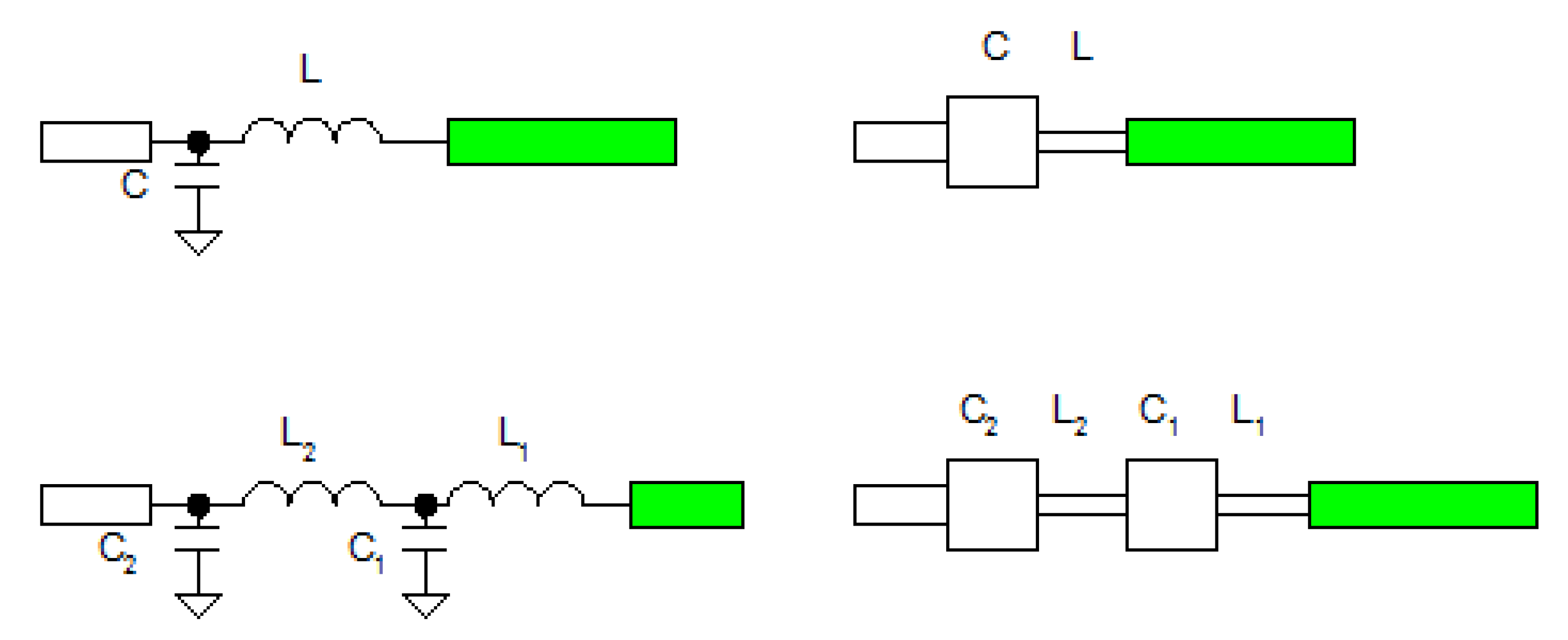
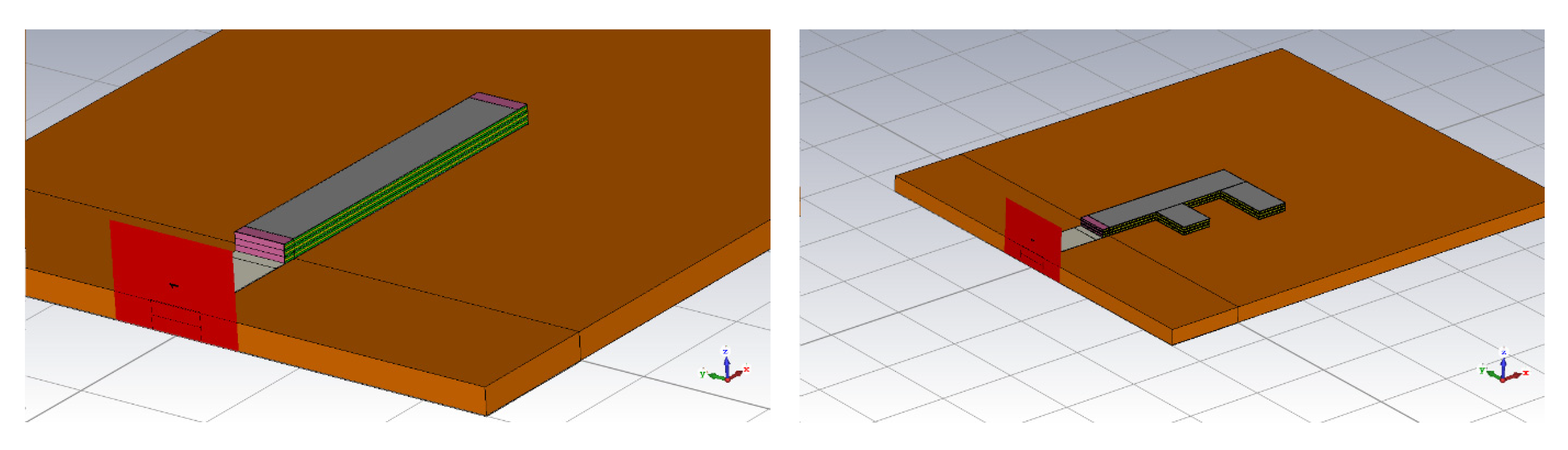
3.3. Design of Antenna
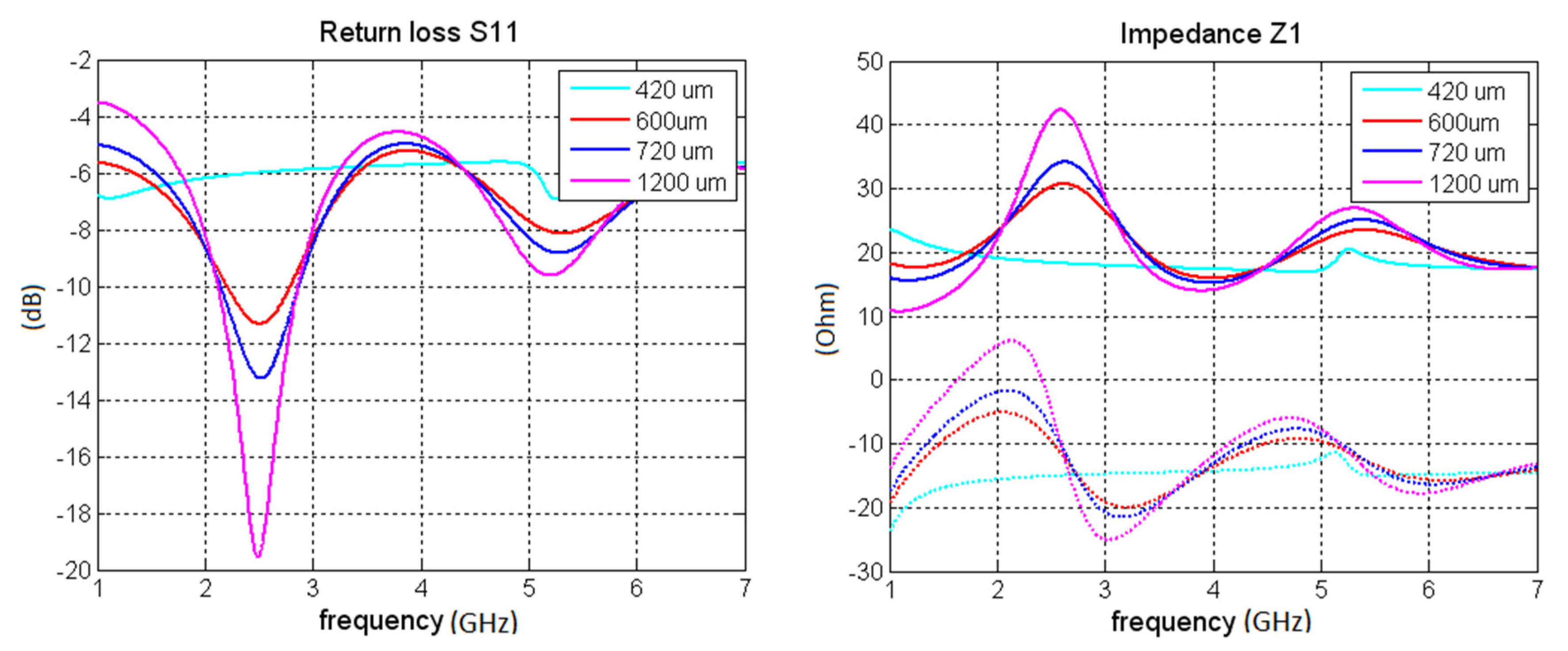
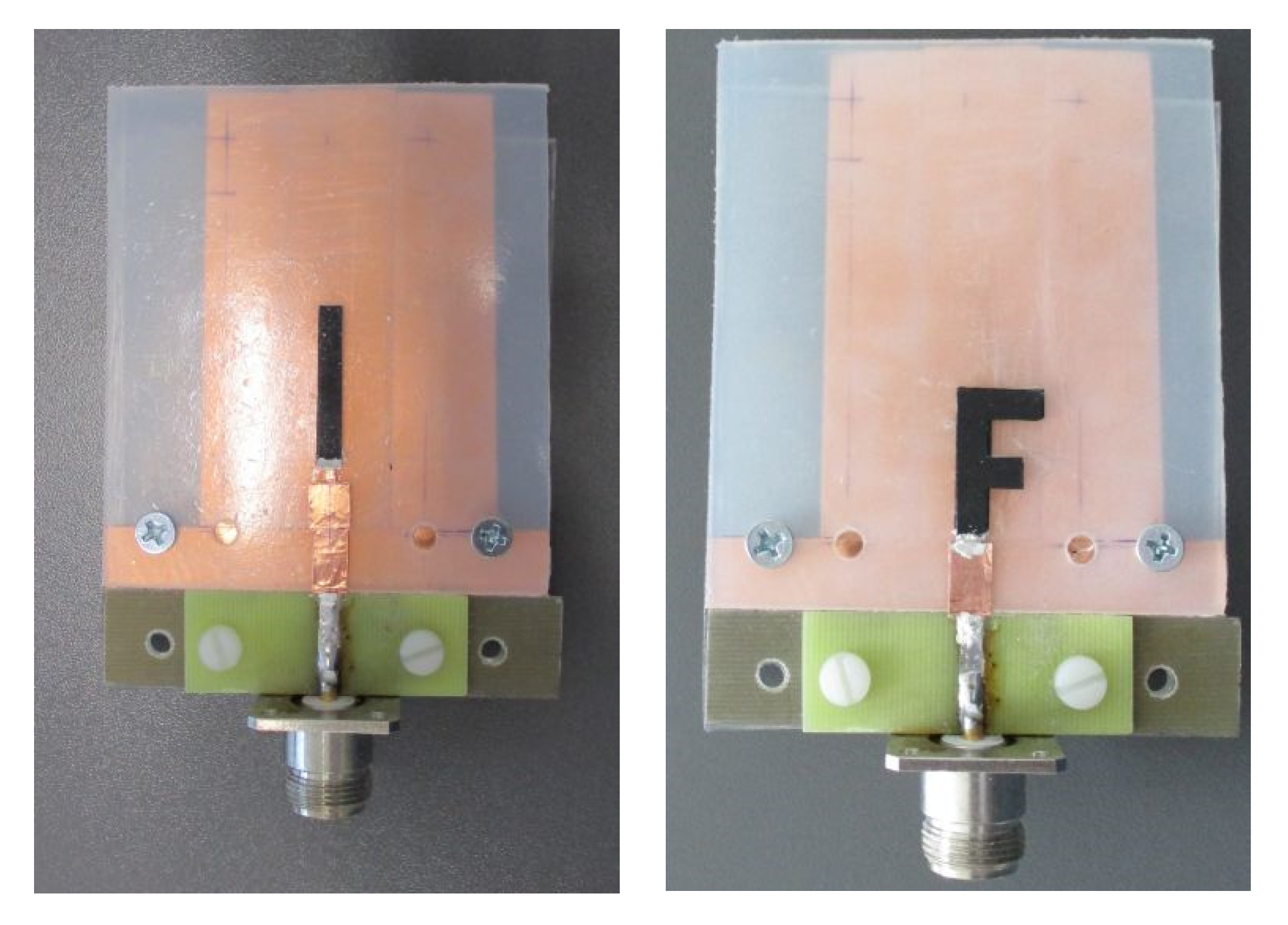
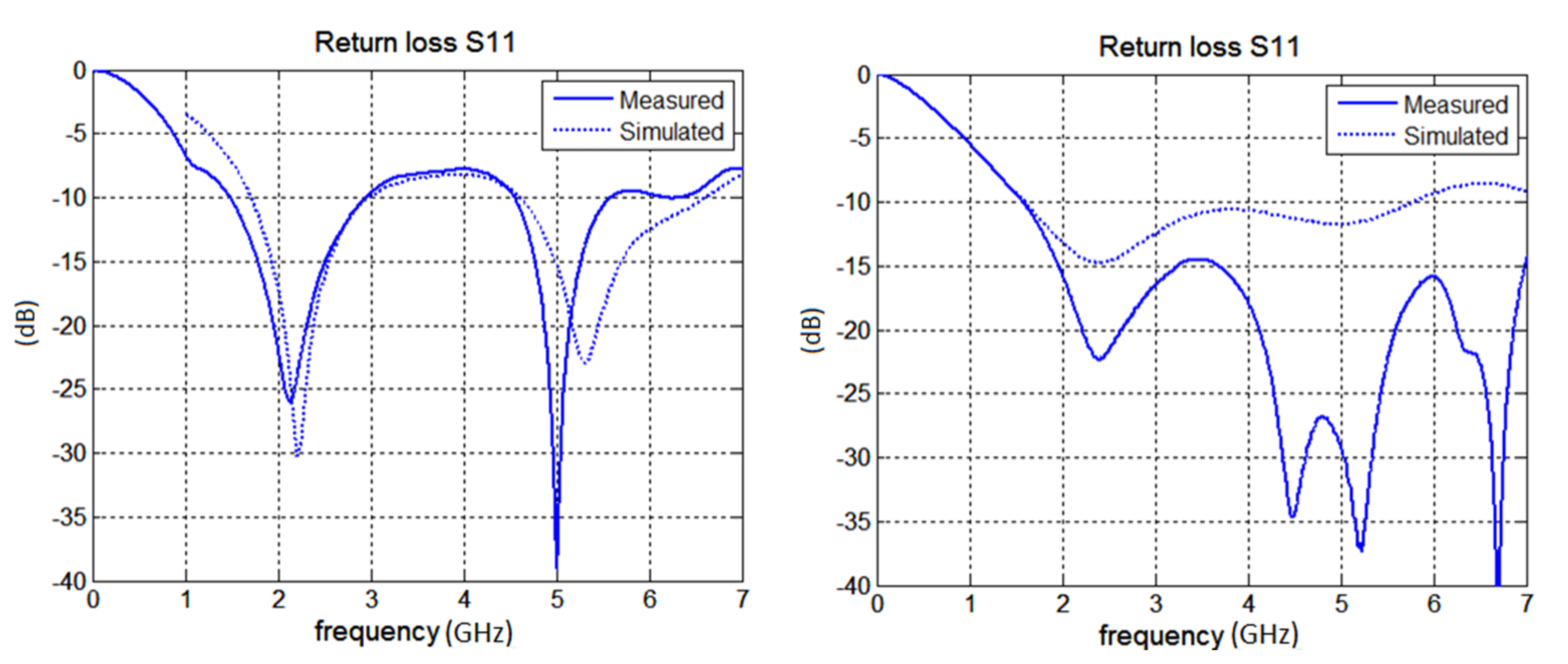
3.4. Fullwave Simulations of the Antenna and Measurements
4. Conclusions
Author Contributions
Funding
Conflicts of Interest
References
- Qiu, Q.; Zhu, M.; Li, Z.; Qiu, K.; Liu, X.; Yu, J.; Ding, B. Highly flexible, breathable, tailorable and washable power generation fabrics for wearable electronics. Nano Energy 2019, 58, 750–758. [Google Scholar] [CrossRef]
- Zamarayeva, A.M.; Ostfeld, A.E.; Wang, M.; Duey, J.K.; Deckman, I.; Lechêne, B.P.; Davies, G.; Steingart, D.A.; Arias, A.C. Flexible and stretchable power sources for wearable electronics. Sci. Adv. 2017, 3, e1602051. [Google Scholar] [CrossRef] [PubMed]
- Andreu-Perez, J.; Leff, D.R.; Ip, H.M.D.; Yang, G.-Z. From Wearable Sensors to Smart Implants-–Toward Pervasive and Personalized Healthcare. IEEE Trans. Biomed. Eng. 2015, 62, 2750–2762. [Google Scholar] [CrossRef] [PubMed]
- Zhu, Z.; Liu, T.; Li, G.; Li, T.; Inoue, Y. Wearable Sensor Systems for Infants. Sensors 2015, 15, 3721–3749. [Google Scholar] [CrossRef] [PubMed]
- Trung, T.Q.; Lee, N. Flexible and Stretchable Physical Sensor Integrated Platforms for Wearable Human-Activity Monitoringand Personal Healthcare. Adv. Mater. 2016, 28, 4338–4372. [Google Scholar] [CrossRef]
- Parrilla, M.; Cánovas, R.; Jeerapan, I.; Andrade, F.J.; Wang, J. A Textile-Based Stretchable Multi-Ion Potentiometric Sensor. Adv. Health Mater. 2016, 5, 996–1001. [Google Scholar] [CrossRef] [PubMed]
- Ponomarenko, A.T.; Shevchenko, V.G.; Enikolopyan, N.S. Formation processes and properties of conducting polymer composites. Adv. Polym. Sci. 1990, 96, 125–147. [Google Scholar] [CrossRef]
- Locher, I.; Klemm, M.; Kirstein, T.; Troster, G. Design and Characterization of Purely Textile Patch Antennas. IEEE Trans. Adv. Packag. 2006, 29, 777–788. [Google Scholar] [CrossRef]
- Salvado, L.; Loss, C.; Gonçalves, R.; Pinho, P. Textile Materials for the Design of Wearable Antennas: A Survey. Sensors 2012, 12, 15841–15857. [Google Scholar] [CrossRef]
- Rmili, H.; Miane, J.-L.; Zangar, H.; Olinga, T. Design of microstrip-fed proximity-coupled conducting-polymer patch antenna. Microw. Opt. Technol. Lett. 2006, 48, 655–660. [Google Scholar] [CrossRef]
- Matyas, J.; Olejnik, R.; Slobodian, P. Flexible microstrip antenna based on carbon nanotubes/(ethylene–octene copolymer) thin composite layer deposited on PET substrate. In Proceedings of the 6th International Conference on Materials and Applications for Sensors and Transducers, Athens, Greece, 27–30 September 2017; Volume 939. [Google Scholar]
- Olejnik, R.; Slobodian, P.; Matyas, J.; Babar, D.G. High elastic polyurethane/carbon nanotube composite laminate for structure health monitoring by gain shifting of antenna sensing element. In Proceedings of the 5th International Conference on Materials and Applications for Sensors and Transducers, Mykonos, Greece, 27–30 September 2015; Volume 108. [Google Scholar]
- Matyas, J.; Munster, L.; Olejnik, R.; Vlcek, K.; Slobodian, P.; Krcmar, P.; Urbanek, P.; Kuritka, I. Antenna of silver nanoparticles mounted on a flexible polymer substrate constructed using inkjet print technology. Jpn. J. Appl. Phys. 2016, 55, 02BB13. [Google Scholar] [CrossRef]
- Matyas, J.; Slobodian, P.; Munster, L.; Olejnik, R.; Urbanek, P. Microstrip antenna from silver nanoparticles printed on a flexible polymer substrate. Mater. Today Proc. 2017, 4, 5030–5038. [Google Scholar] [CrossRef]
- Hamouda, Z.; Wojkiewicz, J.-L.; Pud, A.; Belaabed, B.; Bergheul, S.; Lasri, T. Polyaniline-carbon nanotubes composites Based patch antenna. In Proceedings of the 8th European Conference on Antennas and Propagation, The Hague, The Netherlands, 6–11 April 2014; p. 2197. [Google Scholar]
- Hamouda, Z.; Wojkiewicz, J.-L.; Pud, A.; Kone, L.; Belaabed, B.; Bergheul, S.; Lasri, T. Dual-Band Elliptical Planar Conductive Polymer Antenna Printed on a Flexible Substrate. IEEE Trans. Antennas Propag. 2015, 63, 5864–5867. [Google Scholar] [CrossRef]
- Verma, A.; Fumeaux, C.; Truong, V.T.; Bates, B.D. A 2 GHz Polypyrrole Microstrip Patch Antenna on Plexiglas (TM) Substrate. In Proceedings of the 2009 Asia Pacific Microwave Conference, Singapore, 7–10 December 2009; p. 36. [Google Scholar]
- Chen, S.J.; Fumeaux, C.; Talemi, P.; Chivers, B.; Shepherd, R. Progress in conductive polymer antennas based on free-standing polypyrrole and PEDOT: PSS. In Proceedings of the 2016 17th International Symposium on Antenna Technology and Applied Electromagnetics, Montreal, QC, Canada, 10–13 July 2016. [Google Scholar]
- Kaufmann, T.; Shepherd, R.; Fumeaux, C. Modeling Conductive Polymer Antennas in the Microwave Region. In Proceedings of the 2012 IEEE International Conference on Wireless Information Technology and Systems (ICWITS), Maui, HI, USA, 11–16 November 2012; pp. 1–4. [Google Scholar]
- Wang, Y.; Wang, T.; Wang, T.; Zhang, J.; Chen, J.; Yang, R.; Ruan, L.; Wang, B. Facile preparation of multifunctional poly(amide-imide)/polyaniline films: Combining self-cleaning, self-extinguishing, and conductive. Polym. Eng. Sci. 2019, 59, 33–43. [Google Scholar] [CrossRef]
- Wang, Y.; Yu, H.; Li, Y.; Wang, T.; Xu, T.; Chen, J.; Fan, Z.; Wang, Y.; Wang, B. Facile Preparation of Highly Conductive Poly(amide-imide) Composite Films beyond 1000 S m-1 through Ternary Blend Strategy. Polymers 2019, 11, 546. [Google Scholar] [CrossRef] [PubMed]
- Mehdipour, A.; Sebak, A.-R.; Trueman, C.W.; Rosca, I.D.; Hoa, S.V. Reinforced Continuous Carbon-Fiber Composites Using Multi-Wall Carbon Nanotubes for Wideband Antenna Applications. IEEE Trans. Antennas Propag. 2010, 58, 2451–2456. [Google Scholar] [CrossRef]
- Mehdipour, A.; Rosca, I.D.; Sebak, A.-R.; Trueman, C.W.; Hoa, S.V. Carbon Nanotube Composites for Wideband Millimeter-Wave Antenna Applications. IEEE Trans. Antennas Propag. 2011, 59, 3572–3578. [Google Scholar] [CrossRef]
- Braun, H.P.; Perini, S.; Lanagan, M.T. Measurement of the surface resistivity and electrical conductivity of carbon nanotube sheets using the resonant post-method. Mater. Lett. 2016, 167, 297–299. [Google Scholar] [CrossRef]
- Wang, Y.; Chen, J.; Shen, Y.; Wang, T.; Ni, Y.; Zhang, Z.; Sun, L.; Ji, B.; Wang, B. Control of Conductive and Mechanical Performances of Poly(Amide-Imide) Composite Films Utilizing Synergistic Effect of Polyaniline and Multi-Walled Carbon Nanotube. Polym. Eng. Sci. 2018, 59, 224–230. [Google Scholar] [CrossRef]
- Al Moayed, N.N.; Khan, U.; Obol, M.; Gupta, S.; Afsar, M.N. Characterization of Single- and Multi-walled NCarbon Nanotubes at Microwave Frequencies. In Proceedings of the 2007 IEEE Instrumentation & Measurement Technology Conference, Warsaw, Poland, 1–3 May 2007; Volume 1, p. 1951. [Google Scholar]
- Challa, R.K.; Kajfez, D.; Demir, V.; Gladden, J.R.; Elsherbeni, A.Z. Characterization of Multiwalled Carbon Nanotube (MWCNT) Composites in a Waveguide of Square Cross Section. IEEE Microw. Wirel. Components Lett. 2008, 18, 161–163. [Google Scholar] [CrossRef]
- Cvelbar, U.; Markoli, B.; Poberaj, I.; Zalar, A.; Kosec, L.; Spaić, S. Formation of functional groups on graphite during oxygen plasma treatment. Appl. Surf. Sci. 2006, 253, 1861–1865. [Google Scholar] [CrossRef]
- Cvelbar, U. Interaction of non-equilibrium oxygen plasma with sintered graphite. Appl. Surf. Sci. 2013, 269, 33–36. [Google Scholar] [CrossRef]
- Moučka, R.; Goňa, S.; Sedlačík, M. Accurate Measurement of the True Plane-Wave Shielding Effectiveness of Thick Polymer Composite Materials via Rectangular Waveguides. Polymers 2019, 11, 1603. [Google Scholar] [CrossRef] [PubMed]
- Panda, J.R.; Kshetrimayum, R.S. An F-shaped printed monopole antenna for dual-band RFID and WLAN applications. Microw. Opt. Technol. Lett. 2011, 53, 1478–1481. [Google Scholar] [CrossRef]
- Chung, K.T.; Sabo, A.; Pica, A.P. Electrical permittivity and conductivity of carbon black-polyvinyl chloride composites. J. Appl. Phys. 1982, 53, 6867–6879. [Google Scholar] [CrossRef]
- Jou, W.-S.; Cheng, H.-Z.; Hsu, C.-F. The electromagnetic shielding effectiveness of carbon nanotubes polymer composites. J. Alloy. Compd. 2007, 434, 641–645. [Google Scholar] [CrossRef]


| Antenna Type | Parameter | Symbol | Numerical Value |
|---|---|---|---|
| Unipole | length of unipole | l (mm) | 26 |
| width of unipole | w (mm) | 4 | |
| thickness of single composite layer | tc (μm) | 120 | |
| total thickness of unipole (including PET layers) | ttot (μm) | 1014 | |
| F-antenna | length of F-antenna | l (mm) | 21 |
| length of first arm | l1 (mm) | 11 | |
| length of second arm | l2 (mm) | 7 | |
| width of F-antenna | w (mm) | 4 | |
| separation between arms | s (mm) | 5.9 | |
| thickness of single composite layer | tc (μm) | 70 | |
| total thickness of F-antenna (including PET layers) | ttot (μm) | 714 |
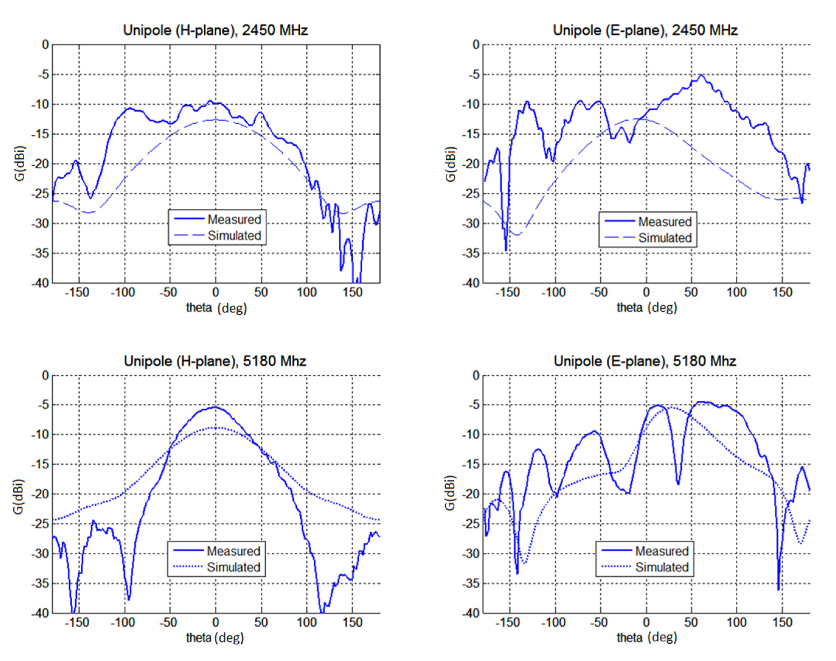
| Antenna Type | Frequency (MHz) | Simulated Gain (dBi) | Measured Gain (dBi) | Simulated Radiation Efficiency (%) |
|---|---|---|---|---|
| Unipole | 2450 | −12.7 | −10.0 | 3.6 |
| 5180 | −8.9 | −5.5 | 6.8 | |
| F-antenna | 2450 | −15.8 | −12.0 | 2.2 |
| 5180 | −11.9 | −11.4 | 4.0 |
Publisher’s Note: MDPI stays neutral with regard to jurisdictional claims in published maps and institutional affiliations. |
© 2020 by the authors. Licensee MDPI, Basel, Switzerland. This article is an open access article distributed under the terms and conditions of the Creative Commons Attribution (CC BY) license (http://creativecommons.org/licenses/by/4.0/).
Share and Cite
Olejník, R.; Goňa, S.; Slobodian, P.; Matyáš, J.; Moučka, R.; Daňová, R. Polyurethane-Carbon Nanotubes Composite Dual Band Antenna for Wearable Applications. Polymers 2020, 12, 2759. https://doi.org/10.3390/polym12112759
Olejník R, Goňa S, Slobodian P, Matyáš J, Moučka R, Daňová R. Polyurethane-Carbon Nanotubes Composite Dual Band Antenna for Wearable Applications. Polymers. 2020; 12(11):2759. https://doi.org/10.3390/polym12112759
Chicago/Turabian StyleOlejník, Robert, Stanislav Goňa, Petr Slobodian, Jiří Matyáš, Robert Moučka, and Romana Daňová. 2020. "Polyurethane-Carbon Nanotubes Composite Dual Band Antenna for Wearable Applications" Polymers 12, no. 11: 2759. https://doi.org/10.3390/polym12112759
APA StyleOlejník, R., Goňa, S., Slobodian, P., Matyáš, J., Moučka, R., & Daňová, R. (2020). Polyurethane-Carbon Nanotubes Composite Dual Band Antenna for Wearable Applications. Polymers, 12(11), 2759. https://doi.org/10.3390/polym12112759