Study on Surface Properties of Aramid Fiber Modified in Supercritical Carbon Dioxide by Glycidyl-POSS


Abstract
:
1. Introduction
2. Surface Treatment Process and Characterization
2.1. Materials
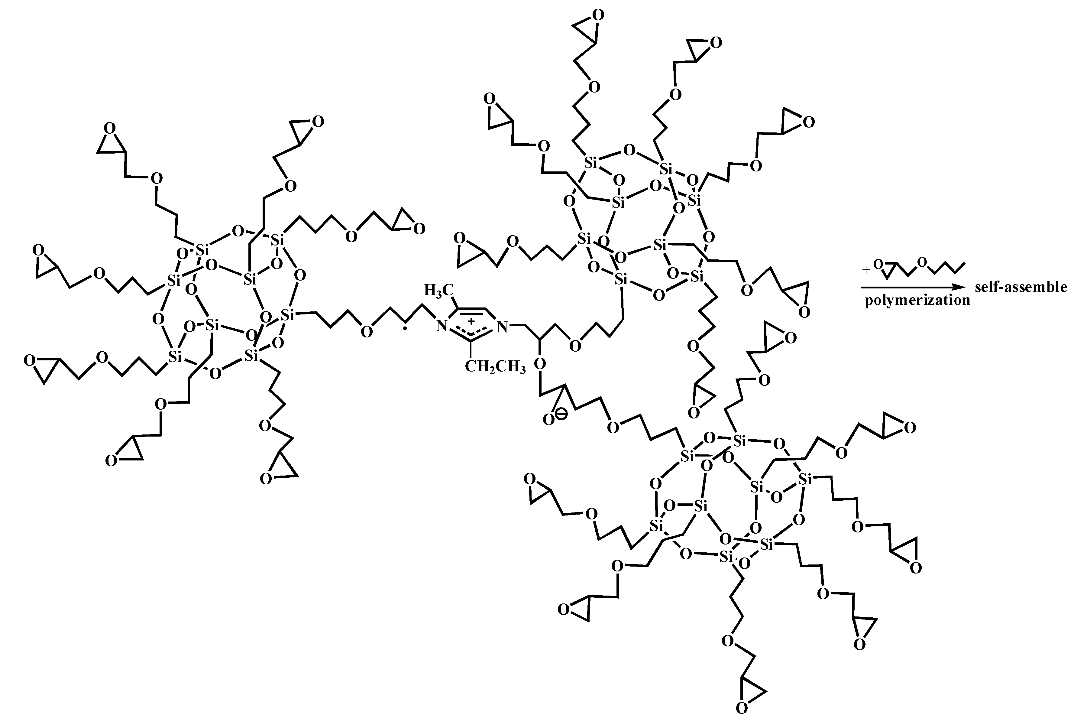
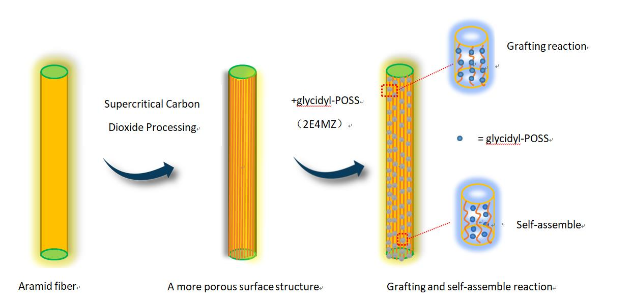
2.2. Preparation of Modified Aramid Fiber
2.3. Characterizations
2.4. Measurements of the Interfacial Shear Strength (IFSS)
2.5. Measurements of the Interlaminar Shear Strength (ILSS)
3. Results and Discussion
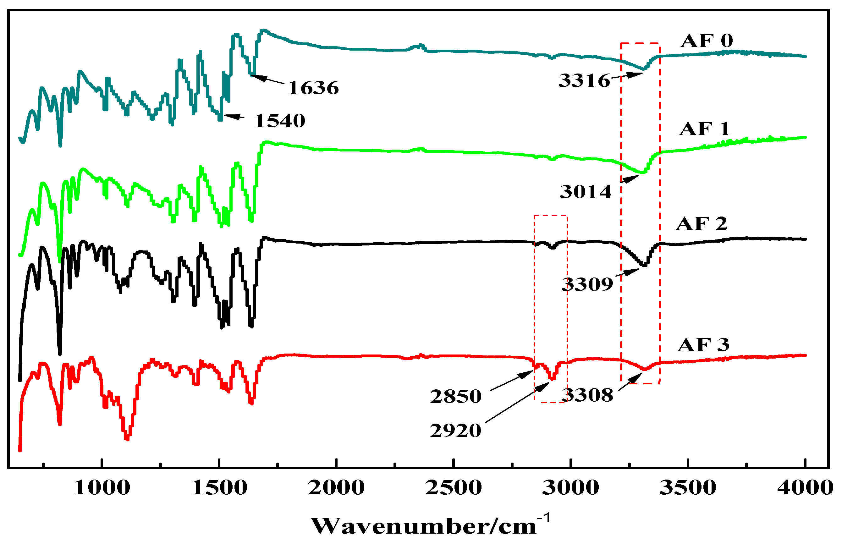
3.1. FTIR and XPS
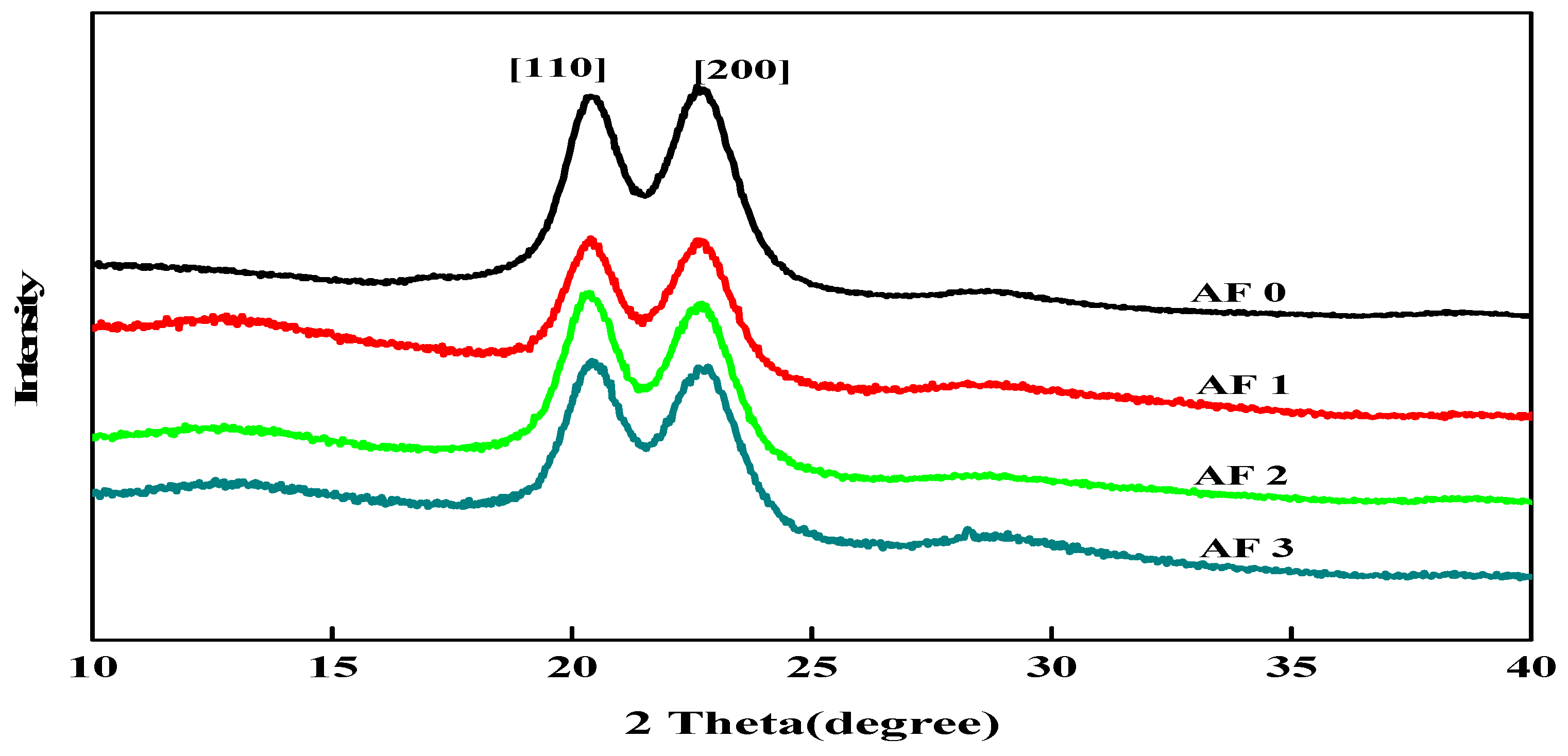
3.2. XRD Results
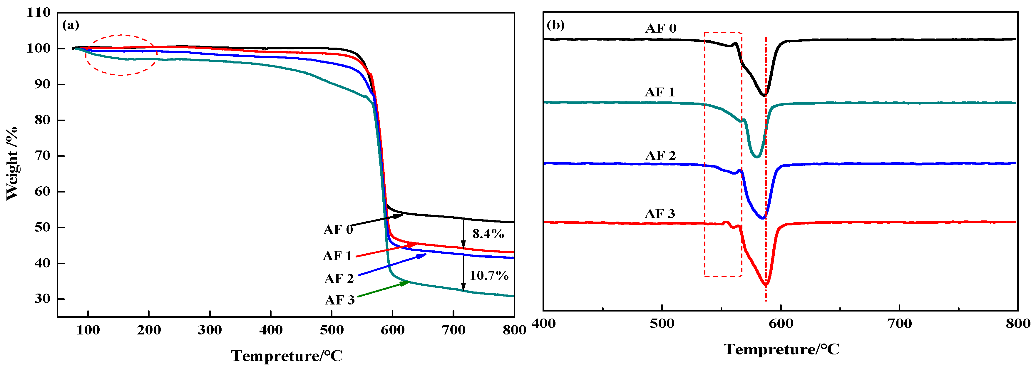
3.3. TG and DTG
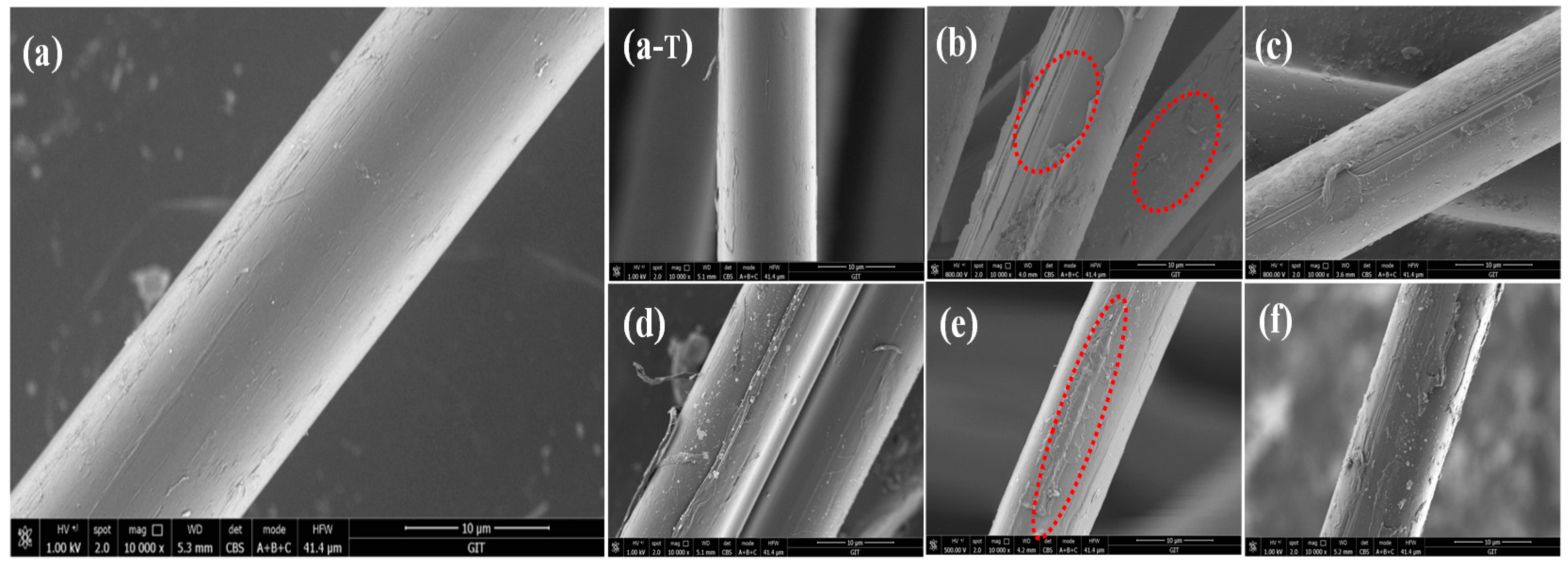
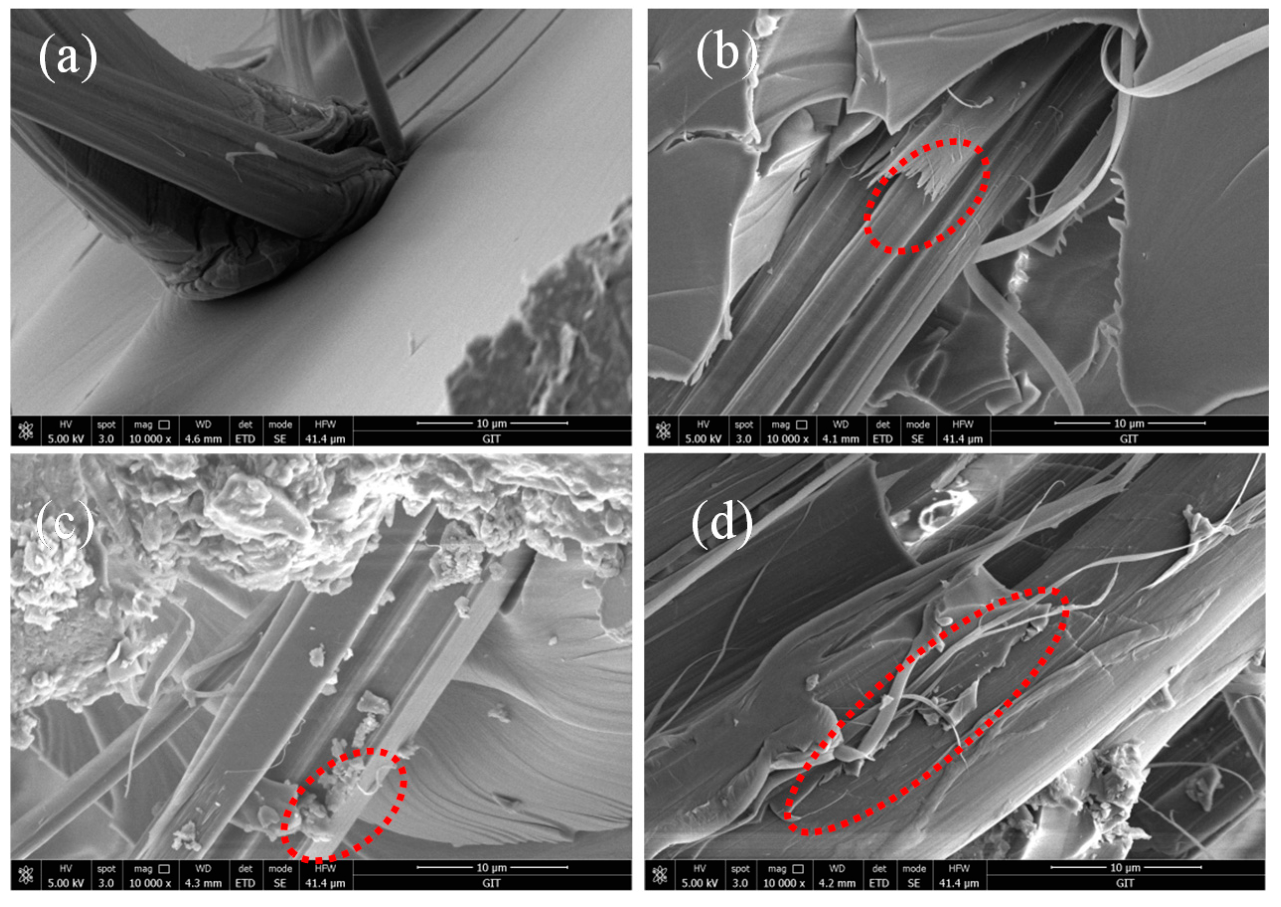
3.4. Surface Morphology of the Aramid Fibers
3.5. Atomic Force Microscopy
3.6. Monofilament Tensile Strength
3.7. The Mechanical Performance
4. Conclusions
Author Contributions
Funding
Conflicts of Interest
References
- Luo, L.; Wu, P.; Cheng, Z.; Hong, D.; Li, B.; Wang, X.; Liu, X. Drect fluorination of para-aramid fiber 1: Fluorination reaction process of PPTA fiber. J. Fluor. Chem. 2016, 186, 12–18. [Google Scholar] [CrossRef]
- Palola, S.; Sarlin, E.; Kolahgar Azari, S.; Koutsos, V.; Vuorinen, J. Microwave induced hierarchical nanostructures on aramid fibers and their infuence on adhesion properties in a rubber matrix. Appl. Surf. Sci. 2017, 410, 145–153. [Google Scholar] [CrossRef]
- Cheng, Z.; Chen, C.; Huang, J.Y.; Chen, T.; Liu, Y.; Liu, X.Y. Nondestructive grafting of PEI on aramid fiber surface through the coordination of Fe (III) to enhance composite interfacial properties. Appl. Surf. Sci. 2017, 401, 323–332. [Google Scholar] [CrossRef]
- Xing, L.X.; Liu, L.; Huang, Y.D.; Jiang, D.W.; Jiang, B.; He, J.M. Enhance interfacial properties of domestic aramid fiber-12 via high energy gamma ray irradiation. Compos. Part B Eng. 2015, 69, 50–57. [Google Scholar] [CrossRef]
- Chen, J.R.; Zhu, Y.F.; Ni, Q.Q.; Fu, Y.Q.; Fu, X. Surface modification and characterization of aramid fibers with hybrid coating. Appl. Surf. Sci. 2014, 321, 103–108. [Google Scholar] [CrossRef]
- Gao, J.; Dai, Y.Y.; Wang, X.; Huang, J.Y.; Yao, J.; Yang, J.; Liu, X.Y. Effects of diferent fluorination routes on aramid fiber surface structures and interlaminar shear strength of its composites. Appl. Surf. Sci. 2013, 270, 627–633. [Google Scholar] [CrossRef]
- Cao, P.F.; Wojnarowska, Z.; Hong, T.; Carroll, B.; Li, B.R.; Feng, H.B.; Parsons, L.; Wang, W.Y.; Lokitz, B.S.; Cheng, S.W.; et al. A star-shaped single lithium-ion conducting copolymer by grafting a POSS nanoparticle. Polymer 2017, 124, 117–127. [Google Scholar] [CrossRef]
- Yuan, H.; Wang, W.C.; Yang, D.Z.; Zhou, X.F.; Zhao, Z.L.; Zhang, L.; Wang, S.; Feng, J. Hydrophilicity modification of aramid fiber using a linear shape plasma excited by nanosecond pulse. Surf. Coat. Technol. 2018, 344, 614–620. [Google Scholar] [CrossRef]
- Jia, C.X.; Chen, P.; Liu, W.; Li, B.; Wang, Q. Surface treatment of aramid fiber by air dielectric barrier discharge plasma at atmospheric pressure. Appl. Surf. Sci. 2011, 257, 4165–4170. [Google Scholar] [CrossRef]
- Wang, C.X.; Du, M.J.; Lv, C.; Zhou, Q.Q.; Ren, Y.; Liu, G.L.; Jin, L.M. Surface modification of aramid fiber by plasma induced vapor phase graft polymerization of acrylic acid.I. Influence of plasma conditions. Appl. Surf. Sci. 2015, 349, 333–342. [Google Scholar] [CrossRef]
- Mishra, K.; Pandey, G.; Singh, R.P. Enhancing the mechanical properties of an expoxy resin using polyhedral oliomeric silsesquioxane (POSS) as nano-reinforcement. Polym. Test. 2017, 62, 210–218. [Google Scholar] [CrossRef]
- Jing, X.D.; Han, Y.T.; Zheng, L.J.; Zheng, H.D. Surface wettability of supercritical CO2—ionic liquid processed aromatic polyamides. J. CO2 Util. 2018, 27, 289–296. [Google Scholar] [CrossRef]
- Wang, L.; Shi, Y.X.; Chen, S.X.; Wang, W.C.; Tian, M.; Ning, N.Y.; Zhang, L.Q. Highly efficient mussel-like inspired modification of aramid fibers by UV-accelerated catechol/polyamine deposition followed chemical grafting for high-performance polymer composites. Chem. Eng. J. 2017, 314, 583–593. [Google Scholar] [CrossRef]
- Walczak, M.; Januszewski, R.; Franczyk, A.; Marciniec, B. Synthesis of monofunctionalized POSS through hydrosilylation. J. Organomet. Chem. 2018, 872, 73–78. [Google Scholar] [CrossRef]
- Romo-Uribe, A. Viscoelasticity and microstructure of POSS-methyl methacrylate nanocomposites. Dynamics and entanglement dilution. Polymer 2018, 148, 27–38. [Google Scholar] [CrossRef]
- Misasi, J.M.; Jin, Q.F.; Knauer, K.M.; Morgan, S.E.; Wiggins, J.S. Hybrid POSS-Hyperbranched polymer additives for simultaneous reinforcement and toughness improvements in epoxy neyworks. Polymer 2017, 117, 54–63. [Google Scholar] [CrossRef]
- Zhang, C.X.; Wu, G.S.; Jiang, H. Tuning interfacial strength of silicone resin composites by varying the grafting density of octamaleamic acid-POSS modified onto carbon fiber. Compos. Part A Appl. Sci. Manuf. 2018, 109, 555–563. [Google Scholar] [CrossRef]
- He, S.; Sun, G.X.; Cheng, X.D.; Dai, H.M.; Chen, X.F. Nanoporous SiO2 grafted aramid fibers with low thermal conductivity. Compos. Sci. Technol. 2017, 146, 91–98. [Google Scholar] [CrossRef]
- Xing, L.X.; Liu, L.; Xie, F.; Huang, Y.D. Mutual irradiation grafting on indigenous aramid fiber-3 in diethanolamine and epichlorohydrin and its effect on interfacially reinforced epoxy composite. Appl. Surf. Sci. 2016, 375, 65–73. [Google Scholar] [CrossRef]
- Cai, H.; Shen, D.; Yuan, L.; Guan, Q.B.; Gu, A.J.; Liang, J.Z. Developing thermally resistant polydopamine@nano turbostratic BN@CeO2 double core-shell ultraviolet absorber with low light-catalysis activity and its grafted high performance aramid fibers. Appl. Surf. Sci. 2018, 452, 389–399. [Google Scholar] [CrossRef]
- Wang, B.; Duan, Y.G.; Zhang, J.J. Titanium dioxide nanoparticles-coated aramid fiber showing enhanced interfacial strength and UV resisitance properties. Mater. Des. 2016, 103, 330–338. [Google Scholar] [CrossRef]
- Ding, X.M.; Kong, H.J.; Qiao, M.M.; Hu, Z.F.; Yu, M.H. Effect of different pressures on microstructure and mechanical performance of F-III fibers in supercritical carbon dioxide fluid. Materials 2019, 12, 690. [Google Scholar] [CrossRef] [PubMed]
- Cheng, Z.; Han, Y.T.; Luo, L.B.; Liu, X.Y. Grafting degradable coordination polymer on aramid fiber surface to improve its interfacial properties. Mater. Lett. 2018, 233, 102–106. [Google Scholar] [CrossRef]
- Zhang, F.H.; Wang, R.G.; He, X.D.; Wang, C.; Ren, L.N. Interfacial shearing strength and reinforcing mechanisms of an epoxy composite reinforced using a carbon nanotube/carbon fiber hybrid. J. Mater. Sci. 2009, 44, 3574–3577. [Google Scholar] [CrossRef]
- Chen, L.; Hu, Z.; Wu, Z.J.; Wu, G.S.; Ma, L.C.; Zhang, C.H.; Huang, Y.D. POSS-bound ZnO nanowires as interphase for enhancing interfacial strength and hydrothermal aging resistance of PBO fiber/epoxy resin composites. Compos. Part A 2017, 96, 1–8. [Google Scholar] [CrossRef]
- Li, Y.W.; Zhao, F.; Song, Y.J.; Li, J.; Hu, Z.; Huang, Y.D. Interfacial microstructure andproperties of poly(phenylene benzobisoxazole) fiber grafted with grapheme oxide via solvothermal method. Appl. Surf. Sci. 2013, 266, 306–312. [Google Scholar] [CrossRef]
- Cao, K.; Siepermann, C.P.; Yang, M.; Waas, A.M.; Kotov, N.A.; Thouless, M.D.; Arruda, E.M. Reactive aramid nanostructures as high-performance polymeric buildingblocks for advanced composites. Adv. Funct. Mater. 2013, 23, 2072–2080. [Google Scholar] [CrossRef]


| Samples | Treatment Method |
|---|---|
| AF0 | Untreated |
| AF0-T | AF0 sample were treated under 150 °C for 1 h. |
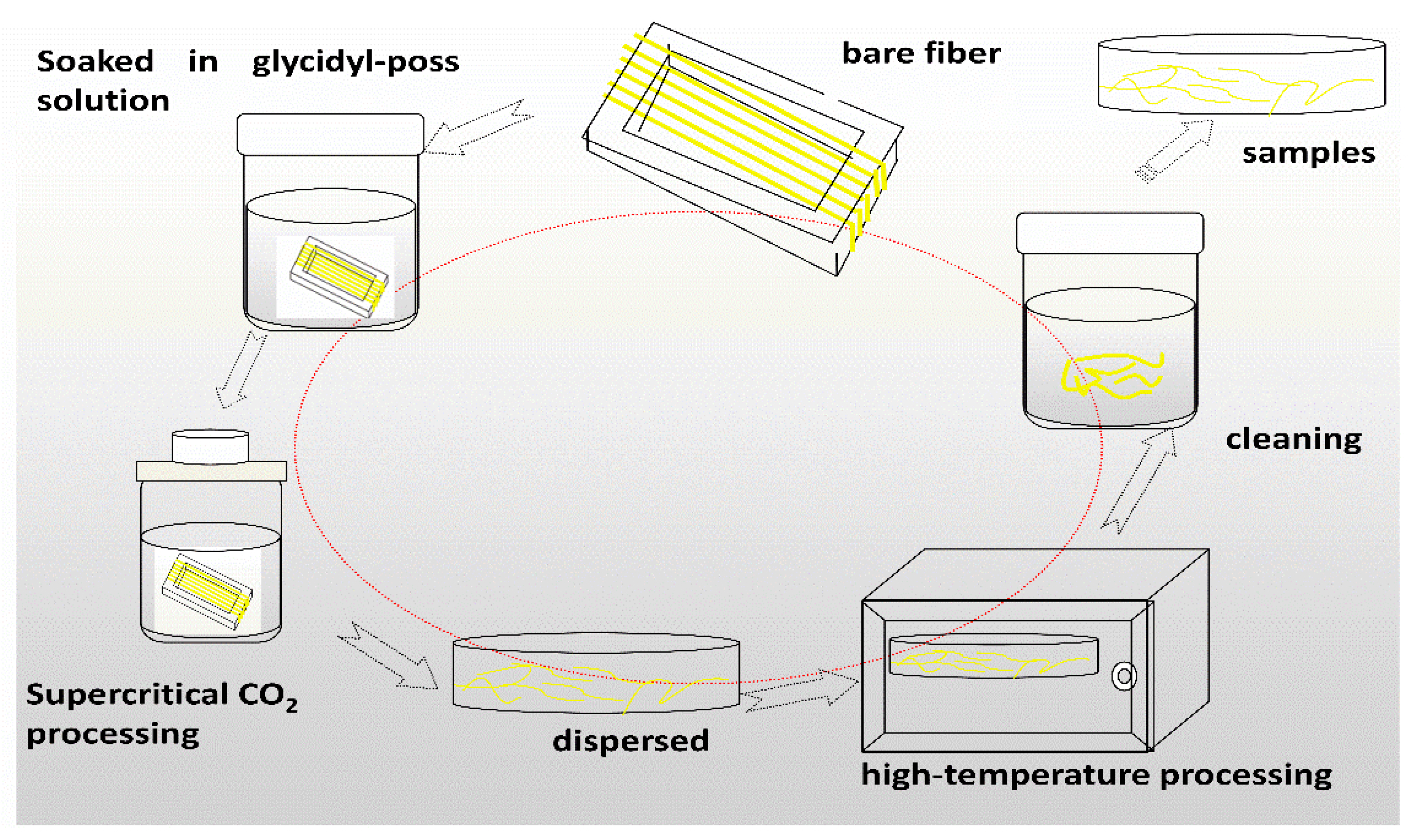
| AF1 | Only scCO2 processing then washed and dried. |
| AF2 | Soaked in glycidyl-POSS solution at 25 °C for 10 min and then treated in scCO2, left to treat in an oven at 150 °C for 1 h, then washed and dried. |
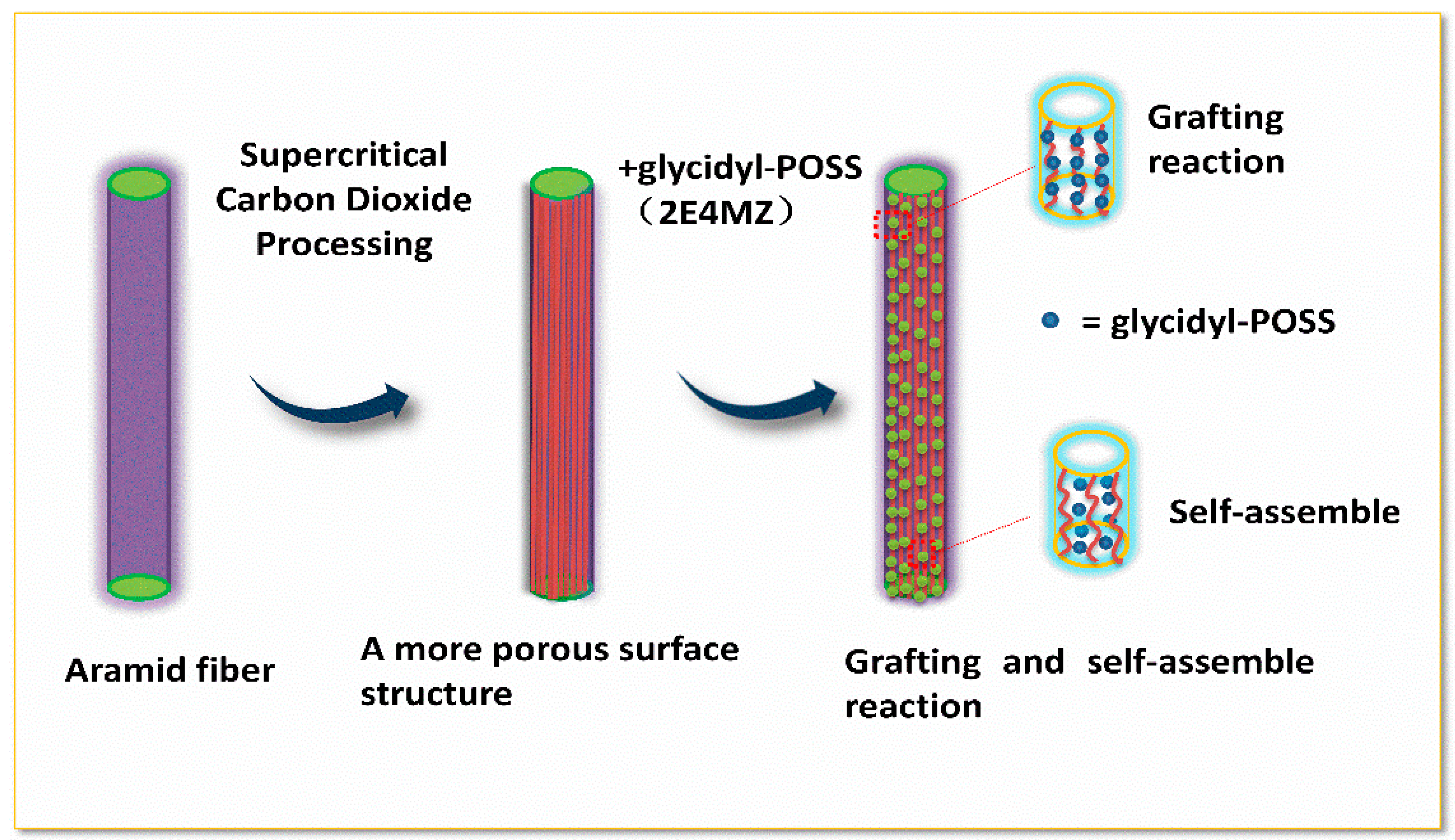
| AF3 | soaked in glycidyl-POSS solution (+5% 2E4MZ) at 25 °C for 10 min and then treated in scCO2, left to treated in an oven at 150 °C for 1 h, then washed and dried. |
| Sample | Chemical Composition (%) | Atomic Ratio | ||||
|---|---|---|---|---|---|---|
| C 1s | O 1s | N 1s | Si | C/N | O/N | |
| AF0 AF0-T | 77.16 83.40 | 12.12 9.51 | 10.72 7.09 | 0 0 | 6.36 11.7 | 1.13 1.34 |
| AF1 | 83.50 | 9.01 | 7.49 | 0 | 11.14 | 1.20 |
| AF2 | 72.49 | 15.98 | 6.28 | 5.25 | 11.54 | 2.54 |
| AF3 | 66.13 | 17.89 | 2.94 | 13.04 | 22.49 | 6.08 |
| Sample | Relative Area of Different Chemical Bonds (%) | |||
|---|---|---|---|---|
| C–C and C=C | O=C–N–H(C=O, C–N) | C–O | –COO– | |
| AF0 AF0-T | 88.15 81.55 | 11.85 18.45 | 0 0 | 0 0 |
| AF1 | 82.54 | 17.46 | 0 | 0 |
| AF2 | 79.93 | 16.84 | 2.49 | 0.74 |
| AF3 | 68.32 | 8.86 | 21.74 | 1.08 |
| Sample | 2θ (°) | D (nm) | FWHM (°) | Xs (nm) | Xc (%) | |||
|---|---|---|---|---|---|---|---|---|
| [110] | [200] | [110] | [200] | [110] | [200] | |||
| AF0 | 20.72 | 23.03 | 4.27 | 3.85 | 1.629 | 1.699 | 4.8 | 82.16 |
| AF1 | 20.34 | 22.63 | 4.36 | 3.92 | 1.439 | 1.589 | 5.4 | 77.10 |
| AF2 | 20.30 | 22.60 | 4.35 | 3.91 | 1.428 | 1.563 | 5.6 | 80.05 |
| AF3 | 20.15 | 22.35 | 4.41 | 4.03 | 1.419 | 1.512 | 6.1 | 74.54 |
| Sample | AF0 | AF1 | AF2 | AF3 |
|---|---|---|---|---|
| Rq/nm | 6.77 | 32.26 | 54.55 | 136.54 |
| Ra/nm | 4.97 | 29.49 | 41.47 | 112.41 |
| Micro-Droplet Sample | IFSS (MPa) | ILSS (MPa) | Increase (Compared with AF0 IFSS/ILSS) |
|---|---|---|---|
| AF0 | 18.90 ± 1.02 | 65.63 ± 2.14 | 0/0 |
| AF1 | 16.79 ± 0.70 | 58.51 ± 2.46 | −11.16%/−10.84% |
| AF2 | 21.10 ± 1.50 | 70.85 ± 2.51 | 11.64%/7.95% |
| AF3 | 24.37 ± 1.29 | 84.26 ± 3.78 | 28.94%/25.33% |
© 2019 by the authors. Licensee MDPI, Basel, Switzerland. This article is an open access article distributed under the terms and conditions of the Creative Commons Attribution (CC BY) license (http://creativecommons.org/licenses/by/4.0/).
Share and Cite
Li, Y.; Luo, Z.; Yang, L.; Li, X.; Xiang, K. Study on Surface Properties of Aramid Fiber Modified in Supercritical Carbon Dioxide by Glycidyl-POSS. Polymers 2019, 11, 700. https://doi.org/10.3390/polym11040700
Li Y, Luo Z, Yang L, Li X, Xiang K. Study on Surface Properties of Aramid Fiber Modified in Supercritical Carbon Dioxide by Glycidyl-POSS. Polymers. 2019; 11(4):700. https://doi.org/10.3390/polym11040700
Chicago/Turabian StyleLi, Yang, Zhu Luo, Le Yang, Xiaolong Li, and Kun Xiang. 2019. "Study on Surface Properties of Aramid Fiber Modified in Supercritical Carbon Dioxide by Glycidyl-POSS" Polymers 11, no. 4: 700. https://doi.org/10.3390/polym11040700
APA StyleLi, Y., Luo, Z., Yang, L., Li, X., & Xiang, K. (2019). Study on Surface Properties of Aramid Fiber Modified in Supercritical Carbon Dioxide by Glycidyl-POSS. Polymers, 11(4), 700. https://doi.org/10.3390/polym11040700