Interaction of Edge Dislocations with Graphene Nanosheets in Graphene/Fe Composites


Abstract
:1. Introduction
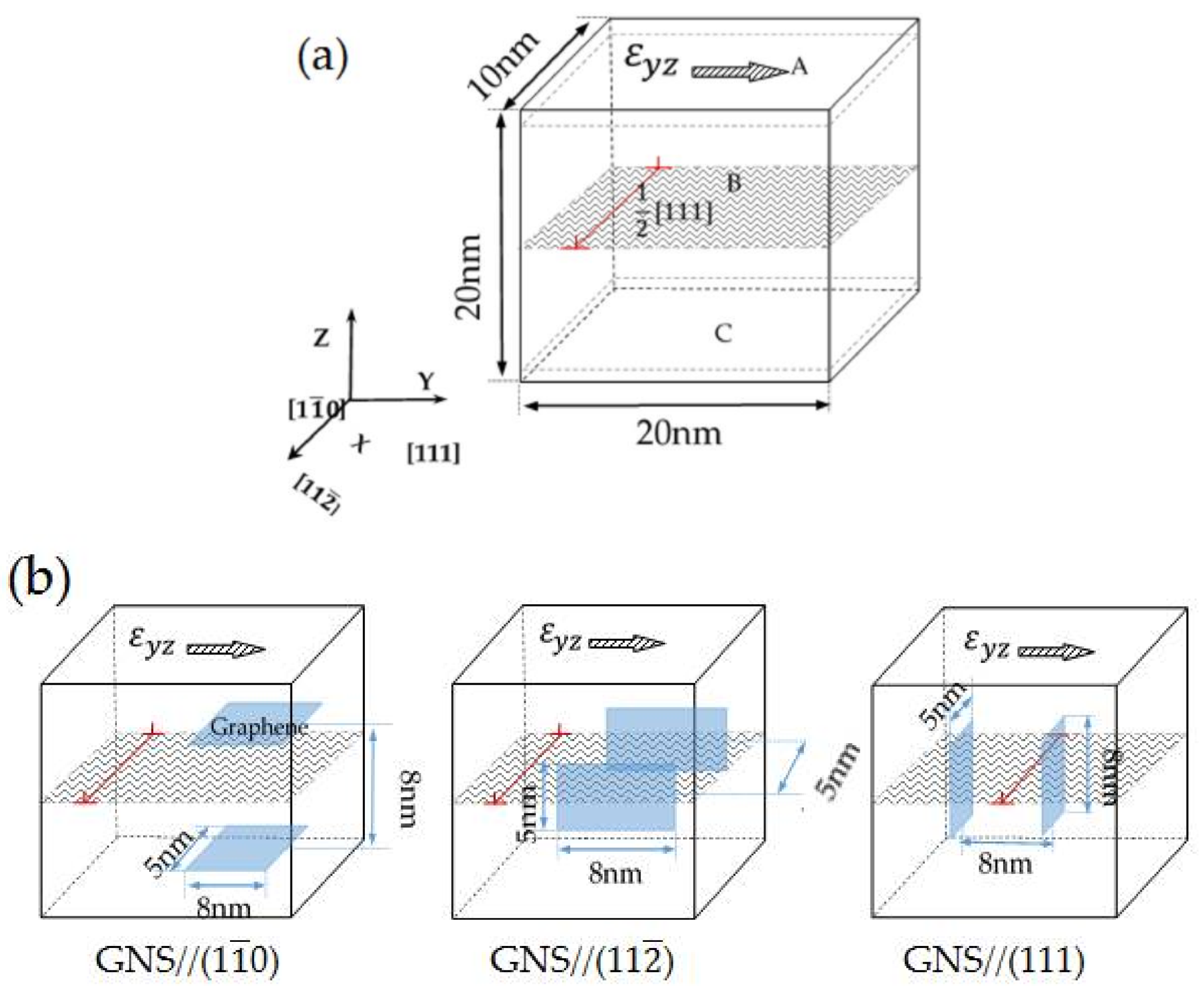
2. Model Setup and Interatomic Potential
3. Results and Discussion
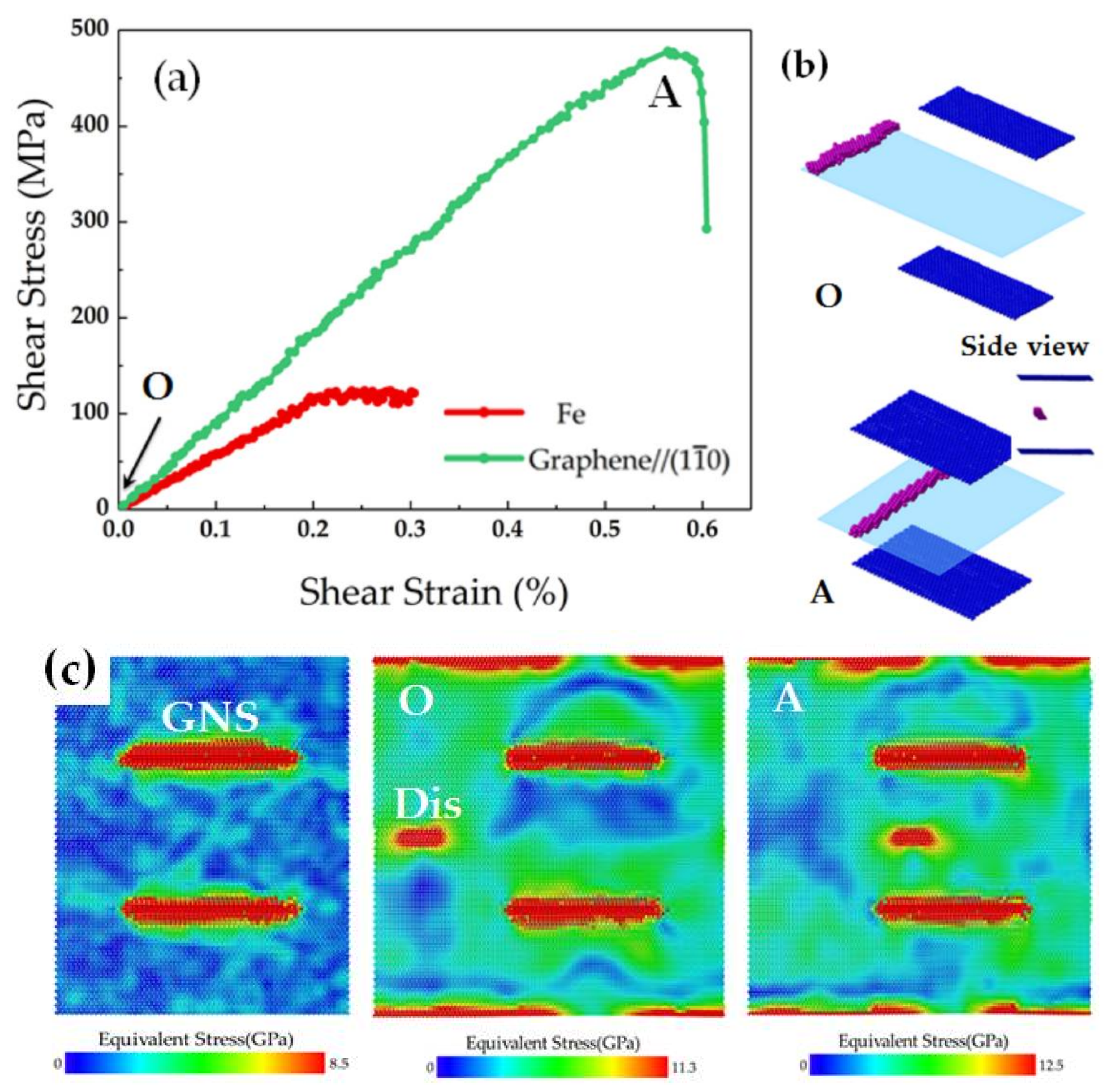
3.1. Interaction between the Edge Dislocation and GNS Pair Parallel to the (110) Plane
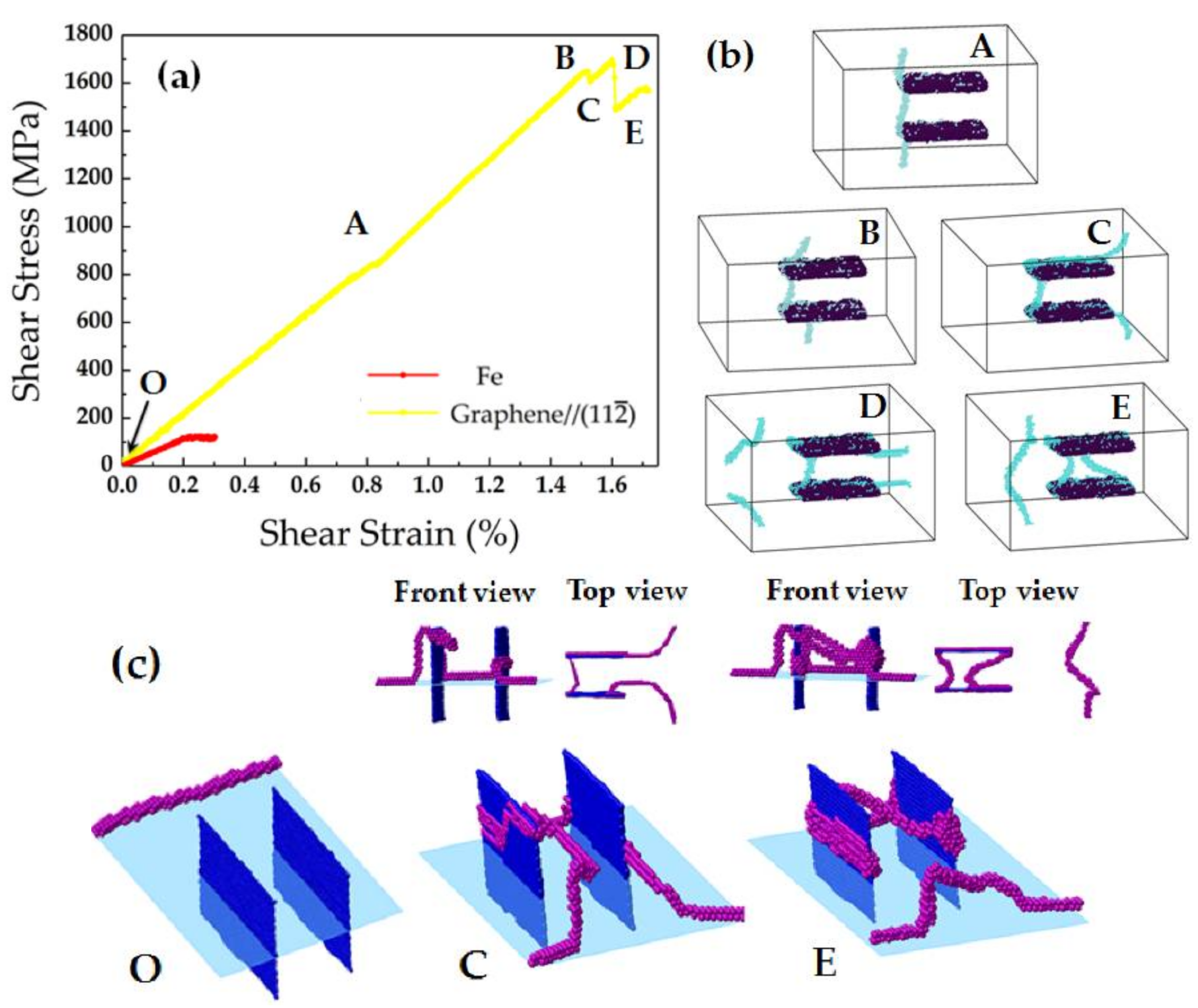
3.2. Interaction between the Edge Dislocation and GNS Pair Parallel to the (112) Plane
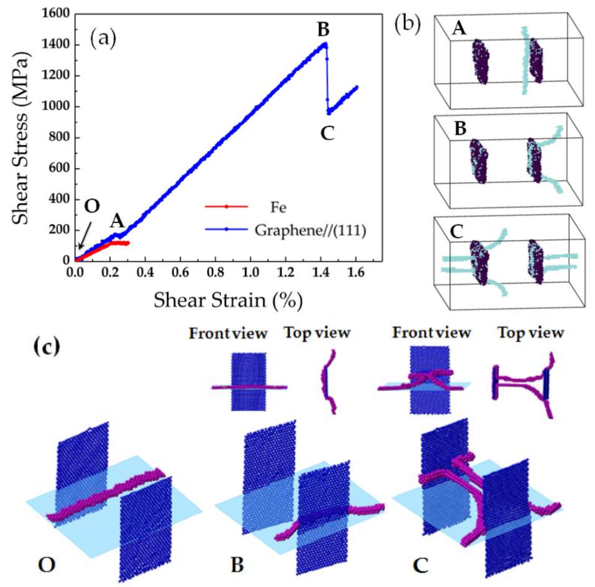
3.3. Interaction with the Edge Dislocation and GNS Pair Parallel to the (111) Plane
4. Conclusions
- It is clear that the GNSs provide an efficient barrier to dislocation motion in the GNS/Fe composite.
- When the GNS was parallel to the (10) plane, the shear modulus and yield stress was 86.6 GPa and 479.9 MPa, an increase of 54% and 336%, respectively, compared to the unreinforced matrix.
- When the GNS was parallel to the (11) plane, the shear modulus and yield stress for the dislocation-GNS interaction was 116.7 GPa and 1647.3 MPa, an increase of 107% and 1400%, respectively, compared to the unreinforced case, where the Orowan “by-passing” strengthening mechanism was observed.
- When the GNS was parallel to the (111) plane, the shear modulus and yield stress for the interaction were 103.3 GPa and 1401 MPa, an increase of 83% and 1173%, respectively, compared to the unreinforced iron. The Orowan “by-passing” mechanism was also observed.
- Comparing the mechanical behavior of the iron matrix composite reinforced by GNS pairs located at different places in the iron matrix, the interaction of the edge dislocation and GNS pair parallel to the (11) plane had the strongest blockage effect, resulting in an ultra-high strength of the respective graphene/Fe composite.
Acknowledgments
Author Contributions
Conflicts of Interest
References
- Novoselov, K.S.; Geim, A.K.; Morozov, S.V.; Jiang, D.; Zhang, Y.; Dubonos, S.V.; Grigorieva, I.V.; Firsov, A.A. Electric field effect in atomically thin carbon films. Science 2004, 306, 666–669. [Google Scholar] [CrossRef] [PubMed]
- Lee, C.; Wei, X.; Kysar, J.W.; Hone, J. Measurement of the elastic properties and intrinsic strength of monolayer graphene. Science 2008, 321, 385–388. [Google Scholar] [CrossRef] [PubMed]
- Novoselov, K.S. Graphene: Materials in the Flatland (Nobel lecture). Angew. Chem. Int. Ed. 2011, 50, 6986–7002. [Google Scholar] [CrossRef] [PubMed]
- Peng, Q.; Liang, C.; Ji, W.; De, S. A theoretical analysis of the effect of the hydrogenation of graphene to graphane on its mechanical properties. Phys. Chem. Chem. Phys. 2013, 15, 2003–2011. [Google Scholar] [CrossRef] [PubMed]
- Young, R.J.; Kinloch, I.A.; Gong, L.; Novoselov, K.S. The mechanics of graphene nanocomposites: A review. Compos. Sci. Technol. 2012, 72, 1459–1476. [Google Scholar] [CrossRef]
- Papageorgiou, D.G.; Kinloch, I.A.; Young, R.J. Mechanical properties of graphene and graphene-based nanocomposites. Prog. Mater. Sci. 2017, 90, 75–127. [Google Scholar] [CrossRef]
- Bartolucci, S.F.; Paras, J.; Rafiee, M.A.; Rafiee, J.; Lee, S.; Kapoor, D.; Koratkar, N. Graphene–aluminum nanocomposites. Mater. Sci. Eng. A 2011, 528, 7933–7937. [Google Scholar] [CrossRef]
- Jeon, C.H.; Jeong, Y.H.; Seo, J.J.; Tien, H.N.; Hong, S.T.; Yum, Y.-J.; Hur, S.-H.; Lee, K.-J. Material properties of graphene/aluminum metal matrix composites fabricated by friction stir processing. Int. J. Precis. Eng. Manuf. 2014, 15, 1235–1239. [Google Scholar] [CrossRef]
- Wang, J.Y.; Li, Z.Q.; Fan, G.L.; Pan, H.H.; Chen, Z.X.; Zhang, D. Reinforcement with graphene nanosheets in aluminum matrix composites. Scr. Mater. 2012, 66, 594–597. [Google Scholar] [CrossRef]
- Pavithra, C.L.; Sarada, B.V.; Rajulapati, K.V.; Sundararajan, T.N.R.G. A new electrochemical approach for the synthesis of copper-graphene nanocomposite foils with high hardness. Sci. Rep. 2014, 4, 4049. [Google Scholar] [CrossRef] [PubMed]
- Hwang, J.; Yoon, T.; Jin, S.H.; Lee, J.S.; Kim, T.-S.; Hong, S.H.; Jeon, S. Enhanced mechanical properties of graphene/copper nanocomposites using a molecular-level mixing process. Adv. Mater. 2013, 25, 6724–6729. [Google Scholar] [CrossRef] [PubMed]
- Chen, L.Y.; Konishi, H.; Fehrenbacher, A.; Ma, C.; Xu, J.-Q.; Choi, H.; Xu, H.-F.; Pfefferkorn, F.E.; Li, X.-C. Novel nanoprocessing route for bulk graphene nanoplatelets reinforced metal matrix nanocomposites. Scr. Mater. 2012, 67, 29–32. [Google Scholar] [CrossRef]
- Yazdandoost, F.; Boroujeni, A.Y.; Mirzaeifar, R. Nanocrystalline nickel-graphene nanoplatelets composite: Superior mechanical properties and mechanics of properties enhancement at the atomistic level. Phys. Rev. Mater. 2017, 1, 076001. [Google Scholar] [CrossRef]
- Kim, Y.; Lee, J.; Yeom, M.S.; Shin, J.W.; Kim, H.; Cui, Y.; Kysar, J.W.; Hone, J.; Jung, Y.; Jeon, S.; et al. Strengthening effect of single-atomic-layer graphene in metal-graphene nanolayered composites. Nat. Commun. 2013, 4, 2114. [Google Scholar] [CrossRef] [PubMed]
- Tang, Y.X.; Yang, X.M.; Wang, R.R.; Li, M. Enhancement of the mechanical properties of graphene–copper composites with graphene–nickel hybrids. Mater. Sci. Eng. A 2014, 599, 247–254. [Google Scholar] [CrossRef]
- Chu, K.; Wang, F.; Wang, X.; Huang, D.-J. Anisotropic mechanical properties of graphene/copper composites with aligned graphene. Mater. Sci. Eng. A 2018, 713, 269–277. [Google Scholar] [CrossRef]
- Shi, X.H.; Yin, Q.F.; Wei, Y.J. A theoretical analysis of the surface dependent binding, peeling and folding of graphene on single crystal copper. Carbon 2012, 50, 3055–3063. [Google Scholar] [CrossRef]
- Xu, Z.; Buehler, M.J. Interface structure and mechanics between graphene and metal substrates: A first-principles study. J. Phys. Condens. Matter 2010, 22, 485301. [Google Scholar] [CrossRef] [PubMed]
- Song, H.Y.; Zha, X.W. Mechanical properties of Ni-coated single graphene sheet and their embedded aluminum matrix composites. Commun. Theor. Phys. 2010, 54, 143. [Google Scholar]
- Lin, D.; Liu, C.; Cheng, G. Single-layer graphene oxide reinforced metal matrix composites by laser sintering: Microstructure and mechanical property enhancement. Acta Mater. 2014, 80, 183–193. [Google Scholar] [CrossRef]
- Plimpton, S. Fast parallel algorithms for short-range molecular-dynamics. J. Comput. Phys. 1995, 117, 1–19. [Google Scholar] [CrossRef]
- Parrinello, M.; Rahman, A. Polymorphic transitions in single crystals: A new molecular dynamics method. J. Appl. Phys. 1981, 52, 7182–7190. [Google Scholar] [CrossRef]
- Chu, Y.; Ragab, T.; Basaran, C. The size effect in mechanical properties of finite-sized graphene nanoribbon. Comput. Mater. Sci. 2014, 81, 269–274. [Google Scholar] [CrossRef]
- Brenner, D.W.; Shenderova, O.A.; Harrison, J.A.; Stuart, S.J.; Ni, B.; Sinnott, S.B. A second-generation reactive empirical bond order (REBO) potential energy expression for hydrocarbons. J. Phys. Condens. Matter 2002, 14, 783–802. [Google Scholar] [CrossRef]
- Deng, B.; Hou, J.; Zhu, H.; Liu, S.; Liu, E.; Shi, Y.F.; Peng, Q. The normal-auxeticity mechanical phase transition in graphene. 2D Mater. 2017, 4, 2. [Google Scholar] [CrossRef]
- Becquart, C.S.; Raulot, J.M.; Bencteux, G.; Domain, S.; Perez, M.; Garruchet, S.; Nguyen, H. Atomistic modeling of an Fe system with a small concentration of C. Comput. Mater. Sci. 2007, 40, 119–129. [Google Scholar] [CrossRef]
- Daw, M.S.; Baskes, M.I. Embedded-atom method: Derivation and application to impurities, surfaces, and other defects in metals. Phys. Rev. B 1984, 29, 6443–6453. [Google Scholar] [CrossRef]
- Stuart, S.J.; Tutein, A.B.; Harrison, J.A. A reactive potential for hydrocarbons with intermolecular interactions. J. Chem. Phys. 2000, 112, 6472–6486. [Google Scholar] [CrossRef]
- Dewapriya, M.A.N.; Meguid, S.A. Atomistic modeling of out-of-plane deformation of a propagating Griffith crack in graphene. Acta Mech. 2017, 228, 3063–3075. [Google Scholar] [CrossRef]
- Hoover, W.G. Canonical dynamics: Equilibrium phase-space distributions. Phys. Rev. A Gen. Phys. 1985, 31, 1695–1697. [Google Scholar] [CrossRef] [PubMed]
- Zhou, M. A new look at the atomic level virial stress: On continuum-molecular system equivalence. Proc. R. Soc. A Math. Phys. Eng. Sci. 2003, 459, 2347–2392. [Google Scholar] [CrossRef]
- Tsuzuki, H.; Branicio, P.S.; Rino, J.P. Structural characterization of deformed crystals by analysis of common atomic neighborhood. Comput. Phys. Commun. 2007, 177, 518–523. [Google Scholar] [CrossRef]
- Stukowski, A. Visualization and analysis of atomistic simulation data with OVITO—The open visualization tool. Model. Simul. Mater. Sci. Eng. 2010, 18. [Google Scholar] [CrossRef]
- Terentyev, D.; Bacon, D.J.; Osetsky, Y.N. Interaction of an edge dislocation with voids in alpha-iron modelled with different interatomic potentials. J. Phys. Condens. Matter 2008, 20, 445007. [Google Scholar] [CrossRef]
- Li, J.; Liu, B.; Fang, Q.; Huang, Z.W.; Liu, Y.W. Atomic-scale strengthening mechanism of dislocation-obstacle interaction in silicon carbide particle-reinforced copper matrix nanocomposites. Ceram. Int. 2017, 43, 3839–3846. [Google Scholar] [CrossRef]
- Lehtinen, A.; Granberg, F.; Laurson, L.; Nordlund, K.; Alava, M.J. Multiscale modeling of dislocation-precipitate interactions in Fe: From molecular dynamics to discrete dislocations. Phys. Rev. E 2016, 93, 013309. [Google Scholar] [CrossRef] [PubMed]


| GNS Parallel to | Remove One-Layer Atoms | Remove Two-Layer Atoms | Remove Three-Layer Atoms |
|---|---|---|---|
| (10) plane |  Cross-section on (111) plane | ||
| Etotal = −1538128 eV | Etotal = −1533452 eV | Etotal = −1533865 eV | |
| (11) plane | 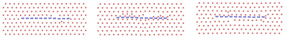 Cross-section on (10) plane | ||
| Etotal = −1535742 eV | Etotal = −1533997 eV | Etotal = −1532950 eV | |
| (111) plane |  Cross-section on (10) plane | ||
| Etotal = −1536170 eV | Etotal = −1535710 eV | Etotal = −1535084 eV | |
| Fe | GNS//(10) | GNS//(11) | GNS//(111) | |||
|---|---|---|---|---|---|---|
| Approach | Depin | Approach | Depin | |||
| Shear Modulus (GPa) | 56.4 | 86.6 | 108.6 | 116.7 | 71.1 | 103.3 |
| Yield Stress (MPa) | 110 | 479.9 | 836.6 | 1647.3 | 170.5 | 1401 |
© 2018 by the authors. Licensee MDPI, Basel, Switzerland. This article is an open access article distributed under the terms and conditions of the Creative Commons Attribution (CC BY) license (http://creativecommons.org/licenses/by/4.0/).
Share and Cite
Wang, L.; Jin, J.; Cao, J.; Yang, P.; Peng, Q. Interaction of Edge Dislocations with Graphene Nanosheets in Graphene/Fe Composites. Crystals 2018, 8, 160. https://doi.org/10.3390/cryst8040160
Wang L, Jin J, Cao J, Yang P, Peng Q. Interaction of Edge Dislocations with Graphene Nanosheets in Graphene/Fe Composites. Crystals. 2018; 8(4):160. https://doi.org/10.3390/cryst8040160
Chicago/Turabian StyleWang, Lu, Jianfeng Jin, Jingyi Cao, Peijun Yang, and Qing Peng. 2018. "Interaction of Edge Dislocations with Graphene Nanosheets in Graphene/Fe Composites" Crystals 8, no. 4: 160. https://doi.org/10.3390/cryst8040160
APA StyleWang, L., Jin, J., Cao, J., Yang, P., & Peng, Q. (2018). Interaction of Edge Dislocations with Graphene Nanosheets in Graphene/Fe Composites. Crystals, 8(4), 160. https://doi.org/10.3390/cryst8040160