Abstract
This study demonstrates that flexible white LEDs, doped with diffusion particles and with a square column structure, have excellent luminosity, uniformity, and bending reliability. This large area (5 cm × 5 cm) square column flexible device had a smaller thickness (2 mm), and enhancements in both luminous efficiency (29.5%) and uniformity (44.6%) compared to the characteristics of the 6 mm reference sample. Optimization of the reflective layer coating for the square column, flexible white LED was achieved with a higher luminous efficiency (171 lm/w) and uniformity (92%). We designed a novel lightning bolt electrode to improve reliability and bendability. After the bending test, the blue flexible LED had a lower bending diameter (10 mm) but more bending circles (increased to 2000 times.
1. Introduction
Solid-state lighting is an efficient technology compared to conventional lighting methods, such as incandescent and fluorescent lamps, because of its energy saving properties such as high brightness, green energy, high reliability, low power consumption, and fast response time [1,2,3,4,5]. In general, the most common approach for obtaining white LEDs (W-LEDs) in the industry is through a combination of GaN-based blue chip with yellow phosphors or luminescent materials [6,7,8]. Although the usage of LEDs is prevalent, many specific applications still require W-LEDs. Large area flexible lighting sources can be extended to applications such as displays, lighting, wearable devices, and biomedicine [9,10,11,12].
The organic light emitting diode (OLED) is one of the candidates for the development and fabrication of flexible lighting devices. OLEDs have attracted attention because of their excellent color quality, sharp contrast, and flexibility for display applications such as mobile phones. However, one of the biggest issues in the current OLED process is the limited lifetime of organic materials, which may cause screen burn. The preparation of OLED requires a water and oxygen free environment. Water damage may also limit the longevity of flexible displays. It is therefore important to improve the process of sealing the packaging when using OLEDs. The blue light produced by OLEDs may degrade significantly. Hence, we think application of inorganic, flexible flip chip LED devices may improve these issues; such devices have several advantages, such as lower heat resistance and voltage, when compared to lateral chip devices. Their wireless capacity contributes to making them a good candidate for a flexible backlighting source with excellent efficiency and reliability.
In the past, J. A. Rogers’ group demonstrated techniques for the manufacture of micro-structured GaAs LEDs, the specialized epitaxial semiconductor layer, transfer printing technology, and any systematic analysis interconnecting related systems formed at the nanoscale [13,14,15,16,17,18]. Other groups investigating the flexible lighting device combined it with solid state lighting and light guide plates [19,20]. However, the light guide plate is not suitable for most flexible applications because of its hard constituent materials, which makes it difficult to bend. Some efforts towards electrode design can also be seen in the design of flexible substrates. Novel materials such as reduced graphene oxide, nitride nanowires, and cellulose/epoxy have been reported [21,22,23]. Although these flexible lighting enhancements offer excellent bending ability, the manufacturing processes are still very complicated.
Our previous works on flexible LEDs were obtained through a combination of the flip-chip LED, silicone-based anisotropic conductive adhesive, and phosphor film [24]. However, this simple design is marred with some drawbacks, such as a large thickness (6 mm), poor reliability due to limited bending times, and bad reflectivity by green cove layer on the substrate. Improvement of bending times is an important consideration in development of flexible LEDs for wearable applications for in the future. Apart from the reliability issue, it is a great challenge to reduce the thickness and simultaneously improve the uniformity of flexible LEDs. This study investigates the shape of a lightning bolt shaped electrode layout that improves the reliability (bending ability) and optical design (square column structure), reduces the thickness and improves the uniformity of a high reflectivity substrate to enhance the efficiency of flexible LEDs.
2. Experimental Section
White flexible LEDs were fabricated using the shape of a lightning bolt and a conventional electrode layout. Figure 1a–d shows the conventional electrode layout, and Figure 1e–h shows the shape of the lightning bolt electrode with the flip chip bonding layout. The gaps between the p- and n- pads in both the electrode layout designs were approximately 100 µm, and the same flip chip was used with the same bonding parameters. Figure 1a,e shows clear schemes for the original layout and lightning layout. From our bending tests performed under these two designs, a very distinct difference in max number of bendings to failure (bending test times: 2000 vs. 500) was observed. Even before the simulation was performed, the shape of electrode and thus the adhesive played important roles. In the conventional design, a breakage could easily develop on the line between the electrodes. However, in the current design, the stress was redistributed over a wider area defined by the lightning bolt shape, and thus the breakage was no longer a line perpendicular to the stress, but more like a zigzag which was partially parallel and partially perpendicular to the stress. This greatly enhanced the durability of the structure under bending, as was proven by our bending tests. As shown in Figure 1d,h, these two types of flexible LEDs were bent repeatedly, after which the flip chip was peeled off from the substrate of the conventional sample. As per the results, the shape of the lightning bolt electrode layout sample demonstrated an excellent reliability for flip chip bonding, and it is a suitable candidate for fabrication of flexible LEDs.
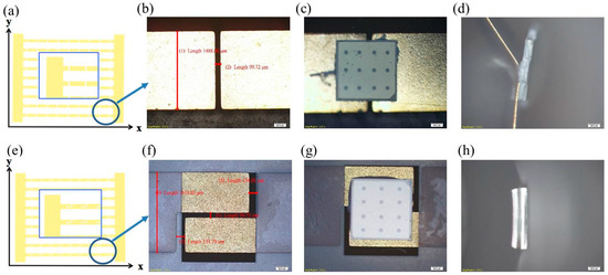
Figure 1.
(a–c) The conventional electrode layout with poor reliability for the bending condition; (d) break scheme of conventional electrode after bending tests; (e–g) the lightning bolt shaped electrode layout with excellent reliability for flip chip bonding. (h) Lightning bolt electrode maintained same status after bending tests.
Figure 2 shows the experimental procedure for fabricating the square column structure of a white flexible LED. The lightning bolt electrode layout was fabricated on the polyimide (PI) substrate, with 0.5 oz copper foil shielding tape on the surface, coated by white cover layer. The pattern was defined by photolithography and wet-etch, and a silicone-based anisotropic conductive adhesive was dropped on the layout along with 45 × 45 mil blue LEDs, which stuck on the substrate. The LED flip chip bonding process was based on a conductive adhesive bonding approach. The bond head temperature and the bonding pressure were set at 230 °C and 2250 g force (gf), respectively. After a 9 × 9 blue chip bonding process was completed, 20 nm 5 wt % Al2O3 (n = 1.77) particles were mixed with silicone glue for the square column structure molding. After the mold, the blue chip was covered by the square column structure, and cured by baking for an hour at 50 °C to produce the light substrate. After curing, polydimethylsiloxane (PDMS) glue was poured into the mold and re-cured by baking it for 2 h at 60 °C. Finally, we prepared 5 wt % phosphor (Y3Al5O12:Ce3+) with a blended PDMS film of thickness 200 µm. The PDMS film was stuck on the light substrate to produce flexible white LEDs with a square column structure. The flexible white LEDs produced using the same fabrication flow but without the square column structure were used as the reference sample.
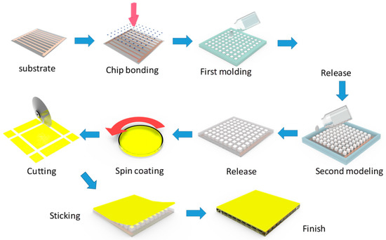
Figure 2.
The process flow illustration of the flexible white LED structure, which was optimized by the layout design and square column structure molding.
In the square column structure, 5 wt % 20 nm Al2O3 (n = 1.77) scattering particles were added in order to simulate the scattering characteristics of Al2O3 diffusion powder, and 20 wt % 0.25 μm TiO2 (n = 2.55) film with 90% reflectivity was used as our reflective layer. Figure 3a,b shows a cross-section of the molding image of the device and flexible substrate. The width (W) and height (H) of the square column structure were controlled by the design. The uniformity in this study was calculated using the following Equation [25,26].
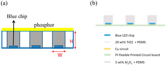
Figure 3.
(a) The column structure of the flexible LED with varied height and width; (b) flexible substrate side view cross-section.
Lmax and Lmin represent the maximal and minimal luminance intensity among the several measured points of the large lighting area, respectively. The calculations were based on multiple points of the sample, therefore the maximal and minimal luminance across various points of the flexible LEDs were taken into consideration. The height and width of the column structure affected uniformity and efficiency greatly in our experiment results. Particles of 5 wt % Al2O3 were mixed with PDMS in the column and used as the diffuser. It was therefore possible to observe that when a strong Lambertian light pattern passed through this structure, the photons were scattered, and the taller the column, the stronger the scattering effect was. Thus, the uniformity of the H = 2 and 3 mm can be expected to be higher in a wider structure. However, in narrower structures, (smaller W), the tall column could be treated as a light tube or light guide, because the fill factor (the cross-section area of column vs. the overall area) was small; the guiding effect for the shorter height structure (H = 1 mm) was not strong enough to greatly alter the scattering effect, so the H = 1 mm structure had better uniformity. As for the efficiency, the certain absorption (or loss) caused by the Al2O3 particles meant that the taller the square column was, the poorer the final output efficiency was (H = 1 mm > 2 mm > 3 mm). In the experiment results, optimization of W, H, and the concentration of the scattering particles enhanced the uniformity but reduced the efficiency. Selecting the ideal parameters for device optimization is a challenge when fabricating flexible LEDs with a square column structure.
3. Measurement and Analysis
In order to achieve the best flexible sample, the parameters (W, H) of the square column structure could be initially modulated by small flexible devices (2 cm × 2 cm). Figure 4 shows the figure of merit (FOM), which depends on the various W and H values from the experimental results, for the flexible LEDs with a square column structure. The FOM from small samples was used to determine the best structure parameters to be fed into the large (5 cm × 5 cm) sample fabrication. The formula of FOM is defined by Equation 2 as follows:
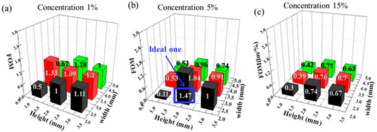
Figure 4.
The figure of merit (FOM) for different heights, widths, and concentrations ofdiffusion particles (a)1% Al2O3 particles doping (b) 3% particles Al2O3 doping (c) 5% particles Al2O3 dopingof a small sized (2 cm × 2 cm) area of flexible LEDs with a square column structure.
The Uniformitycolumn − Uniformityref and Efficiency were defined as the uniformity (particle size) and luminous efficiency deviation between square column structures and reference samples, respectively. The uniformity was defined using Equation (1) and measured using these small-sized flexible LED samples. The highest value FOM gave the ideal parameters for the square column structure sample. According to our calculation in Figure 4, the highest value FOM (1.47) was achieved with the parameters: H = 2 mm, W = 2.5 mm, and 5 wt % diffusion particles. We chose these as the ideal parameters to fabricate the large areas (5 cm × 5 cm) of white flexible LEDs.
With most of the parameters analyzed, a large area (5 cm × 5 cm) of flexible white LED samples (layout by 9 parallels and 9 series) could be fabricated as shown in Figure 5. Figure 5a,b shows the luminous efficiency with the current driven from 1 mA to 700 mA, and emission spectra driven at 120 mA, of the flexible white LED samples. Optical measurements were performed using a spectrometer CAS 140CT (Instrument System GmbH, Munich, Germany). In order to make the LEDs suitable for wearable applications, it was necessary to reduce the thickness of the flexible samples (from 6 mm to 2 mm). Although the thickness of the reference flexible sample was decreased to improve the luminous efficiency, it became less uniform (from 56% to 49%), as shown in Figure 5c. The large area of square column flexible LEDs was fabricated with the parameters H = 2 mm, W = 2.5 mm, and 5 wt % diffusion particles, as determined in the previous section. The scattering particles doped by the square column structure and the white coating layer on the substrate in this device not only improved the luminous efficiency (enhanced by 29.5% from 6 mm reference sample), but also enhanced the uniformity of the thickness (2 mm). Excellent uniformity (81%) was obtained by virtue of the square column structure of the flexible LEDs, as shown in Figure 5c.
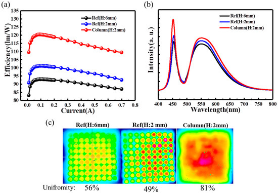
Figure 5.
(a) The luminous efficiency with the current driven from 1 mA to 700 mA, (b) the spectrum, and (c) uniformity of the different thickness in the large size (5 × 5 cm) for reference samples and column flexible LED samples.
To optimize the square column flexible LEDs, the reflective layer was coated on the sidewall. In addition, the reflective layer was coated on the gap between the flip chip and the bottom of the substrate, as shown in Figure 6a. The reflective layer was fabricated by diffusing glue with 20% of TiO2 blended into the silicon. In Figure 6b, the reflective layer showed higher reflectance (90%) than the substrate reference sample (55%) under visible light. The luminous efficiency was improved by 54% after the reflective layer was coated, as shown in Figure 6c. The emission spectrum of the flexible sample with and without the reflective layer is shown in Figure 6d. The reflective layer could scatter blue and yellow rays from the bottom side, which reduced the loss of photons. Apart from the efficiency, the use of a reflective layer modulated the ray trace and improved the uniformity of the flexible LEDs. After optimization, a 92% uniformity of the white flexible LED was achieved, as shown in Figure 6e.
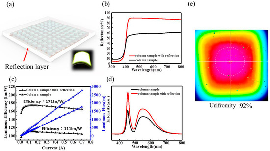
Figure 6.
(a) Illustration reflective layer coating layout of column structure flexible LED. (b) The reflectance spectrum, (c) the luminous efficiency, (d) the emission spectrum, and (e) the uniformity of the flexible LEDs with the reflective layer coating the substrate.
The bending test system was also applied in this study to verify the bending reliability of flexible white LEDs. As shown in Figure 7a, we used metal rollers with different diameters to control the bending diameters. Figure 7b,c shows the performance of the blue and square column white flexible LED samples under different bending conditions. The flexible blue LED arrays did not exhibit significant changes in their output light and electrical characteristics. Figure 7d,e shows the LIV characteristics of the flexible blue LED array, and those with phosphors and square column structures, under many bending cycles. The blue flexible LED were able to complete the bending cycle less than 2000 times, and the flexible white LED below 1000 times. The fail mark plotted in the figure indicates that several chips were destroyed after performing an extended number of bending cycles. According to the results, the lightning bolt electrode layout of the flexible LED samples exhibited excellent bending reliability, and the square column structure not only improved the performance, but also survived under multiple actual bending conditions.
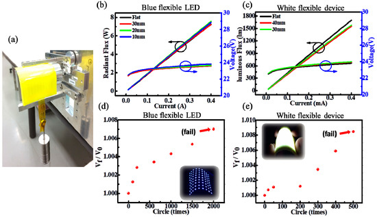
Figure 7.
(a) Image of the bending test measurement system for the square column structure flexible LEDs. The luminous flux and voltage of (b) the blue flexible LEDs and (c) the square column white flexible LEDs with different bending diameters. (d) The bending test of the blue flexible LEDs; (e) white LEDs with many bending cycles.
4. Conclusions
This study demonstrated the design of flexible LEDs with excellent luminosity, uniformity, and bending reliability through the use of a lightning bolt electrode layout and diffusion particles doped by a square column structure. The improvement in width and height of the square column structure, and the concentration of scattering particles, was shown through the experiment results to enhance uniformity but reduce efficiency. After the experimental process, the best parameter was determined to be that of a large area (5 × 5 cm2) device; furthermore, enhancements of 29.5% luminous efficiency and 44.6% uniformity were demonstrated when compared to the characteristics of the 6 mm reference sample. We also developed a reflective layer coating to optimize the flexible LED, achieving an excellent luminous efficiency of 171 lm/w and a uniformity of 92%. For the bending reliability, the flexible blue LED could achieve a bending diameter of 10 mm, and the square column flexible white LED a bending diameter of 30 mm. The bending cycles were completed less than 2000 times for the flexible blue LED, and less than 1000 times for the flexible white LED. We believe that flexible LEDs with excellent luminous efficiency, color uniformity, and bending characteristics will be suitable for display and wearable applications in the future.
Author Contributions
Data curation, C.-H.L.; Conceptualization, C.-H.L. and Y.-M.P.; Methodology, H.-Y.L. and C.-Y.K.; Project administration C.-W.S.; Resources, C.-F.L. and J.-J.Y.; Software, X.-Y.C. and H.-H.T.; Supervision, C.-H.C. and H.-C.K.; Validation, C.-C.L. and P.-T.L.; Writing—original draft, C.-H.L.; Writing—review & editing, C.-H.L. and Y.-M.P.
Funding
This research was funded by the Ministry of Science and Technology of Taiwan through grant numbers: MOST107-2221-E-009-113-MY3, MOST106-2622-E-009-005-CC2, and MOST107-2221-E-009 -114 -MY3.
Acknowledgments
The authors express their gratitude to Lextar Corporation and Dexerials Corporation for their technical support.
Conflicts of Interest
The authors declare no conflict of interest.
References
- Franzl, T.; Koktysh, D.; Klar, T.; Rogach, A.; Feldmann, J.; Gaponik, N. Fast energy transfer in layer-by-layer assembled CdTe nanocrystal bilayers. Appl. Phys. Lett. 2004, 84, 2904–2906. [Google Scholar] [CrossRef]
- Hsu, S.-C.; Ke, L.-A.; Lin, H.-C.; Chen, T.-M.; Lin, H.-Y.; Chen, Y.-Z.; Chueh, Y.-L.; Kuo, H.-C.; Lin, C.-C. Fabrication of a Highly Stable White Light-Emitting Diode with Multiple-Layer Colloidal Quantum Dots. IEEE J. Sel. Top. Quantum Electron. 2017, 23, 1–9. [Google Scholar] [CrossRef]
- Nakamura, S.; Mukai, T.; Senoh, M. Candela-class high-brightness InGaN/AlGaN double-heterostructure blue-light-emitting diodes. Appl. Phys. Lett. 1994, 64, 1687–1689. [Google Scholar] [CrossRef]
- Pai, Y.-M.; Lin, C.-H.; Lee, C.-F.; Lin, C.-P.; Chen, C.-H.; Kuo, H.-C.; Ye, Z.-T. Enhancing the Light-Extraction Efficiency of AlGaN-Based Deep-Ultraviolet Light-Emitting Diodes by Optimizing the Diameter and Tilt of the Aluminum Sidewall. Crystals 2018, 8, 420. [Google Scholar] [CrossRef]
- Schubert, E.F.; Kim, J.K. Solid-state light sources getting smart. Science 2005, 308, 1274–1278. [Google Scholar] [CrossRef] [PubMed]
- Lin, C.-H.; Huang, C.-H.; Pai, Y.-M.; Lee, C.-F.; Lin, C.-C.; Sun, C.-W.; Chen, C.-H.; Sher, C.-W.; Kuo, H.-C. Novel Method for Estimating Phosphor Conversion Efficiency of Light-Emitting Diodes. Crystals 2018, 8, 442. [Google Scholar] [CrossRef]
- Sher, C.-W.; Lin, C.-H.; Lin, H.-Y.; Lin, C.-C.; Huang, C.-H.; Chen, K.-J.; Li, J.-R.; Wang, K.-Y.; Tu, H.-H.; Fu, C.-C. Correction: A high quality liquid-type quantum dot white light-emitting diode. Nanoscale 2018, 10, 6214. [Google Scholar] [CrossRef]
- Tang, Y.-S.; Hu, S.-F.; Ke, W.-C.; Lin, C.C.; Bagkar, N.C.; Liu, R.-S. Near-ultraviolet excitable orange-yellow Sr3(Al2O5)Cl2: Eu2+ phosphor for potential application in light-emitting diodes. Appl. Phys. Lett. 2008, 93, 131114. [Google Scholar] [CrossRef]
- Ahn, J.-H.; Kim, H.-S.; Lee, K.J.; Jeon, S.; Kang, S.J.; Sun, Y.; Nuzzo, R.G.; Rogers, J.A. Heterogeneous three-dimensional electronics by use of printed semiconductor nanomaterials. Science 2006, 314, 1754–1757. [Google Scholar] [CrossRef]
- Lin, C.-H.; Lee, C.-F.; Verma, A.; Lin, H.-Y.; Lin, C.-C.; Sher, C.-W.; Kuo, H.-C. 59-1: Invited Paper: A Full-color Micro-light-emitting-diode Display by a Lithographic-fabricated Photoresist Mold. SID Symp. Dig. Tech. Pap. 2018, 49, 779–781. [Google Scholar] [CrossRef]
- Meitl, M.A.; Zhu, Z.-T.; Kumar, V.; Lee, K.J.; Feng, X.; Huang, Y.Y.; Adesida, I.; Nuzzo, R.G.; Rogers, J.A. Transfer printing by kinetic control of adhesion to an elastomeric stamp. Nat. Mater. 2006, 5, 33. [Google Scholar] [CrossRef]
- Wang, L.; Ma, J.; Liu, Z.; Yi, X.; Zhu, H.; Wang, G. In situ fabrication of bendable microscale hexagonal pyramids array vertical light emitting diodes with graphene as stretchable electrical interconnects. ACS Photonics 2014, 1, 421–429. [Google Scholar] [CrossRef]
- Ahn, B.Y.; Duoss, E.B.; Motala, M.J.; Guo, X.; Park, S.-I.; Xiong, Y.; Yoon, J.; Nuzzo, R.G.; Rogers, J.A.; Lewis, J.A. Omnidirectional printing of flexible, stretchable, and spanning silver microelectrodes. Science 2009, 323, 1590–1593. [Google Scholar] [CrossRef] [PubMed]
- Kim, H.-S.; Brueckner, E.; Song, J.; Li, Y.; Kim, S.; Lu, C.; Sulkin, J.; Choquette, K.; Huang, Y.; Nuzzo, R.G. Unusual strategies for using indium gallium nitride grown on silicon (111) for solid-state lighting. Proc. Natl. Acad. Sci. USA 2011, 108, 10072–10077. [Google Scholar] [CrossRef] [PubMed]
- Kim, R.H.; Kim, S.; Song, Y.M.; Jeong, H.; Kim, T.I.; Lee, J.; Li, X.; Choquette, K.D.; Rogers, J.A. Flexible vertical light emitting diodes. Small 2012, 8, 3123–3128. [Google Scholar] [CrossRef] [PubMed]
- Kim, T.-I.; Hyun Lee, S.; Li, Y.; Shi, Y.; Shin, G.; Dan Lee, S.; Huang, Y.; Rogers, J.A.; Su Yu, J. Temperature-and size-dependent characteristics in ultrathin inorganic light-emitting diodes assembled by transfer printing. Appl. Phys. Lett. 2014, 104, 051901. [Google Scholar] [CrossRef]
- Park, S.-I.; Xiong, Y.; Kim, R.-H.; Elvikis, P.; Meitl, M.; Kim, D.-H.; Wu, J.; Yoon, J.; Yu, C.-J.; Liu, Z. Printed assemblies of inorganic light-emitting diodes for deformable and semitransparent displays. Science 2009, 325, 977–981. [Google Scholar] [CrossRef]
- Yoon, J.; Jo, S.; Chun, I.S.; Jung, I.; Kim, H.-S.; Meitl, M.; Menard, E.; Li, X.; Coleman, J.J.; Paik, U. GaAs photovoltaics and optoelectronics using releasable multilayer epitaxial assemblies. Nature 2010, 465, 329. [Google Scholar] [CrossRef]
- Feng, D.; Yan, Y.; Yang, X.; Jin, G.; Fan, S. Novel integrated light-guide plates for liquid crystal display backlight. J. Opt. 2005, 7, 111. [Google Scholar] [CrossRef]
- Huang, P.-H.; Huang, T.-C.; Sun, Y.-T.; Yang, S.-Y. Large-area and thin light guide plates fabricated using UV-based imprinting. Opt. Express 2008, 16, 15033–15038. [Google Scholar] [CrossRef]
- Bi, Y.-G.; Feng, J.; Li, Y.-F.; Zhang, Y.-L.; Liu, Y.-S.; Chen, L.; Liu, Y.-F.; Guo, L.; Wei, S.; Sun, H.-B. Arbitrary shape designable microscale organic light-emitting devices by using femtosecond laser reduced graphene oxide as a patterned electrode. ACS Photonics 2014, 1, 690–695. [Google Scholar] [CrossRef]
- Gomez, E.F.; Steckl, A.J. Improved performance of OLEDs on cellulose/epoxy substrate using adenine as a hole injection layer. ACS Photonics 2015, 2, 439–445. [Google Scholar] [CrossRef]
- Guan, N.; Dai, X.; Messanvi, A.; Zhang, H.; Yan, J.; Gautier, E.; Bougerol, C.; Julien, F.H.; Durand, C.; Eymery, J. Flexible white light emitting diodes based on nitride nanowires and nanophosphors. ACS Photonics 2016, 3, 597–603. [Google Scholar] [CrossRef] [PubMed]
- Sher, C.-W.; Chen, K.-J.; Lin, C.-C.; Han, H.-V.; Lin, H.-Y.; Tu, Z.-Y.; Tu, H.-H.; Honjo, K.; Jiang, H.-Y.; Ou, S.-L. Large-area, uniform white light LED source on a flexible substrate. Opt. Express 2015, 23, A1167–A1178. [Google Scholar] [CrossRef] [PubMed]
- Karwowski, W. International Encyclopedia of Ergonomics and Human Factors; CRC Press: Boca Raton, FL, USA, 2001; Volume 3. [Google Scholar]
- Tang, K.-H.; Lee, Y.-H.; Wu, T.-H. The development of luminance uniformity measurement for CNT-BLU based on human visual perception. J. Chin. Inst. Chem. Eng. 2011, 28, 179–191. [Google Scholar] [CrossRef]


© 2018 by the authors. Licensee MDPI, Basel, Switzerland. This article is an open access article distributed under the terms and conditions of the Creative Commons Attribution (CC BY) license (http://creativecommons.org/licenses/by/4.0/).