Article

Microstructure and Reciprocating Sliding Wear Resistance Evaluation on SiMo Ductile Iron Low Alloyed with Cobalt

by
Eduardo Colin-García
1,
Alejandro Cruz-Ramírez
2,*,
Marisa Moreno-Ríos
3,
Ricardo Gerardo Sánchez-Alvarado
1,
José Antonio Romero-Serrano
1,
Juan Cancio Jiménez-Lugos
1,
Armando Irvin Martínez-Pérez
3 and
Edgar Ernesto Vera-Cárdenas
3
1
Escuela Superior de Ingeniería Química e Industrias Extractivas, Instituto Politécnico Nacional, Unidad Profesional Adolfo López Mateos, Ciudad de México 07738, Mexico
2
Unidad Profesional Interdisciplinaria de Ingeniería Campus Hidalgo, Instituto Politécnico Nacional, Carretera Pachuca-Actopan km 1-500, San Agustín Tlaxiaca 42162, Mexico
3
División de Estudios de Posgrado e Investigación, Tecnológico Nacional de México/Instituto Tecnológico de Pachuca, Pachuca 42080, Mexico
*
Author to whom correspondence should be addressed.
Crystals 2025, 15(3), 278; https://doi.org/10.3390/cryst15030278
Submission received: 31 January 2025 / Revised: 10 March 2025 / Accepted: 17 March 2025 / Published: 18 March 2025
(This article belongs to the Special Issue Microstructural Characterization and Property Analysis of Alloys)

Abstract

:
High silicon and molybdenum (SiMo) ductile irons present a metallic matrix composed principally of ferrite with little volume fraction of pearlite and carbides. In this work, two SiMo ductile irons with similar levels of silicon, 0.3% Mo (DI-0.3Mo) and 0.6% Mo with 0.8% Co (DI-0.6Mo-0.8Co), were evaluated to determine the effect of molybdenum and cobalt on the microstructure, hardness, and wear performance at room temperature. The microstructural characterization of the ductile irons was performed using light microscopy and SEM-EDS. At the same time, mechanical characterization was carried out using Rockwell C hardness, and wear was evaluated using reciprocating ball-on-flat sliding wear tests. The result showed that DI-0.6Mo-0.8Co obtained the higher nodule count (247 nod/mm2), nodularity (86.69%), volume fraction of ferrite (78.15%), and molybdenum carbides (2.1%), while DI-0.3Mo presented a higher volume fraction of pearlite (12.8%) and free graphite (13.88%). The higher value of Rockwell C hardness with 21.29 HRC was obtained in DI-0.6Mo-0.8Co due to a higher amount of molybdenum carbides. The wear resistance shows that the DI-0.6Mo-0.8Co sample presented the highest wear resistance due to an adequate balance between a ferritic matrix reinforced by the molybdenum and cobalt addition and a high carbide content.

1. Introduction

Cast iron materials are widely used in various industrial components due to their low production cost, excellent castability, good vibration damping, and high thermal conductivity, combined with favorable mechanical properties [1]. In past decades, the most popular casting was gray iron due to its low production cost and admissible mechanical properties; however, its disadvantage was the low ductility and impact energy, attributed to free graphite in flakes form [2]. Ductile irons are a family of cast irons with a good blend of mechanical properties such as ductility, impact toughness, hardness, and strength [3]. This improved performance is due to their microstructure, which consists of free graphite in a spherical form (nodules) within a metallic matrix, typically pearlitic–ferritic [4].
The microstructure and, hence, the mechanical behavior of ductile irons can be modified in two ways: (i) during the foundry process and (ii) applying heat treatments [5]. In the first case, alloying elements are added to improve some nodular features, to obtain a certain microstructure directly from the casting process, and to control the mechanical properties. Nickel is widely used during the casting process to improve nodular features such as nodularity and nodule count [6]. Manganese and copper are added to obtain a full pearlitic matrix, obtaining higher hardness than those obtained in a pearlitic–ferric matrix [7]. During the selection of alloying elements, it is essential to consider their effects on nodular characteristics and the metallic matrix. Elements such as cobalt, a ferrite stabilizer, can increase the nodule count and enhance mechanical properties such as elongation and toughness [8]. On the contrary, low traces of boron near 120 ppm detriment the nodule formation and decrease the pearlite formation until 3% [9]. In the second case, the heat treatments are used to improve a specific mechanical property; the most common heat treatment applied in ductile iron is the isothermal austempering heat treatment, which promotes an ausferritic matrix that increases the hardness, strength, and impact toughness [10]. Quenching and tempering are used to obtain a tempered martensitic matrix, enhancing hardness and wear resistance. In some cases, ferritizing is applied to ductile iron to achieve a ferritic matrix, improving ductility and corrosion resistance [11].
During the foundry process, it is uncommon to combine elements that promote the ferrite phase with carbide-forming elements. However, a kind of ductile iron alloyed with silicon (Si) and molybdenum (Mo), which is designated as SiMo ductile iron, achieves this phase combination. This material presents a modification in the chemical composition of conventional ductile iron, containing higher silicon and molybdenum contents in the range of 4–6% and 0.5–2%, respectively. The matrix resulting from the addition of silicon and molybdenum is molybdenum carbides and pearlite at grain boundaries contained in a ferritic matrix. However, the final microstructure during the casting process of SiMo ductile iron depends on parameters such as chemical composition, inoculation treatment, and cooling rate. These parameters modify the nodule count, the volume fraction of carbides and their precipitation at the grain boundary, and the ferrite matrix [12,13].
SiMo ductile iron presents an adequate balance between high ductility and tensile strength, similar to those obtained in ferric steels. The applications of SiMo ductile iron are due to a good combination of low production cost and mechanical properties at high temperatures [14]. According to Roučka, J. [15], there are two base DIs alloyed with Si and Mo; these are EN-GJS-SiMo40-6, which contains 3.8–4.2% Si and 0.5–0.7% Mo, and EN-GJS-SiMo50-10, with 4.8–5.2% Si and 0.8–1.1% Mo. Considering the raw materials, the chemical composition should be established considering the following: (i) the carbon needs to be adjusted to obtain a carbon equivalent (CE) in the interval of 4.6–4.8; (ii) the manganese content is lower than 3.0%; (iii) other alloy elements need to be adjusted with the manufacturer; (iv) the minimum microstructure is 85% ferrite, a maximum of 0.5% carbides of type Fe2MoC or Fe2MoC/M6C, and the balance of pearlite; and (v) a minimum of 100 nod/mm2. However, it must be considered that molybdenum content is defined based on the specific application [16]: (a) from 0.0 to 0.5% Mo for applications that require large and fast temperature cycles, (b) between 0.5 to 1.0% Mo for creep applications (long time and high temperature), and (c) from 1.5 to 2.0% Mo for applications where high strength and high temperature are required (creep or very high temperature).
Some research on SiMo ductile irons alloying with different elements has evaluated their microstructures and mechanical behavior, mainly at high temperatures. Medeiros de Magalhães [17] studied the effect of additions of Nb in SiMo ductile irons on the microstructure and mechanical properties. The results indicate that niobium can replace molybdenum, attaining similar mechanical properties at high temperatures. Roučka, J. [15] studied the properties of SiMo ductile iron at high temperatures where the tensile strength decreased, while elongation was increased. Stan, L. [18] studied the high-temperature oxidation of inoculated high Si and SiMo ductile iron in the air, showing that a ductile iron containing 2.3% Mo and 4.8% Si promotes pearlite formation; however, the water vapor in the oxidizing atmosphere influences the oxidation of the ductile irons, and this effect depends on the lever of water vapor and heating temperature. There are some works that have focused on the wear behavior of SiMo ductile iron. Dyrlaga, Ł. [19] studied the microstructure and abrasive wear resistance with the pin-on-disc technique at room temperature on SiMo ductile iron alloyed with aluminum and chromium. The results showed that the number of carbides of the M6C, M3C2, and MC types increased, while a misforming of the graphite spheroidal shape appeared with the aluminum addition. Moreover, a higher abrasion resistance (more than twice) was obtained with the highest additions of chromium, molybdenum, and aluminum. Abdelrahim, D. [12] studied the effect of wear behavior in ball-on-disk at room temperature and 250, 500, and 750 °C in SiMo ductile iron. The results showed that wear resistance increases at higher temperatures of 750 °C; this is related to metal–metal interaction (ball test and sample) due to the oxidation layer formed. There are few studies on the wear resistance of SiMo ductile irons considering the effect of cobalt addition, where an increase in the ferritic matrix is expected due to the presence of molybdenum carbides.
Cobalt is widely used as an alloying element for steel due to its high melting point, which exhibits excellent strength at high temperatures, as well as oxidation resistance. The cobalt addition in ductile iron shows a graphitizing effect, which reduces the carbon content in the austenite [20], promotes high nodule count with lower size nodules, and promotes smaller eutectic cell size [21]. Cobalt increases the ferrite content and acts as a hardening of the metallic matrix [22,23]. At high temperatures, the cobalt increases the elongation and impact energy values [21]. It has been reported that increasing the cobalt amount in high silicon ductile iron slightly increases the tensile strength, yield strength, and Brinell hardness at room temperature [23,24,25]. There is a positive correlation between hardness and wear resistance in cast iron, where generally, the harder the cast iron, the more resistant it is to wear. This work aims to study the microstructure, hardness, and wear resistance of SiMo ductile irons with different molybdenum (0.3 and 0.6%) and cobalt (0.8%) contents, keeping the silicon (3.8%) content constant. Microstructural characterization was performed using optical microscopy and SEM-EDS techniques, while hardness measurements and reciprocating ball-on-flat sliding wear standard tests were conducted at room temperature.

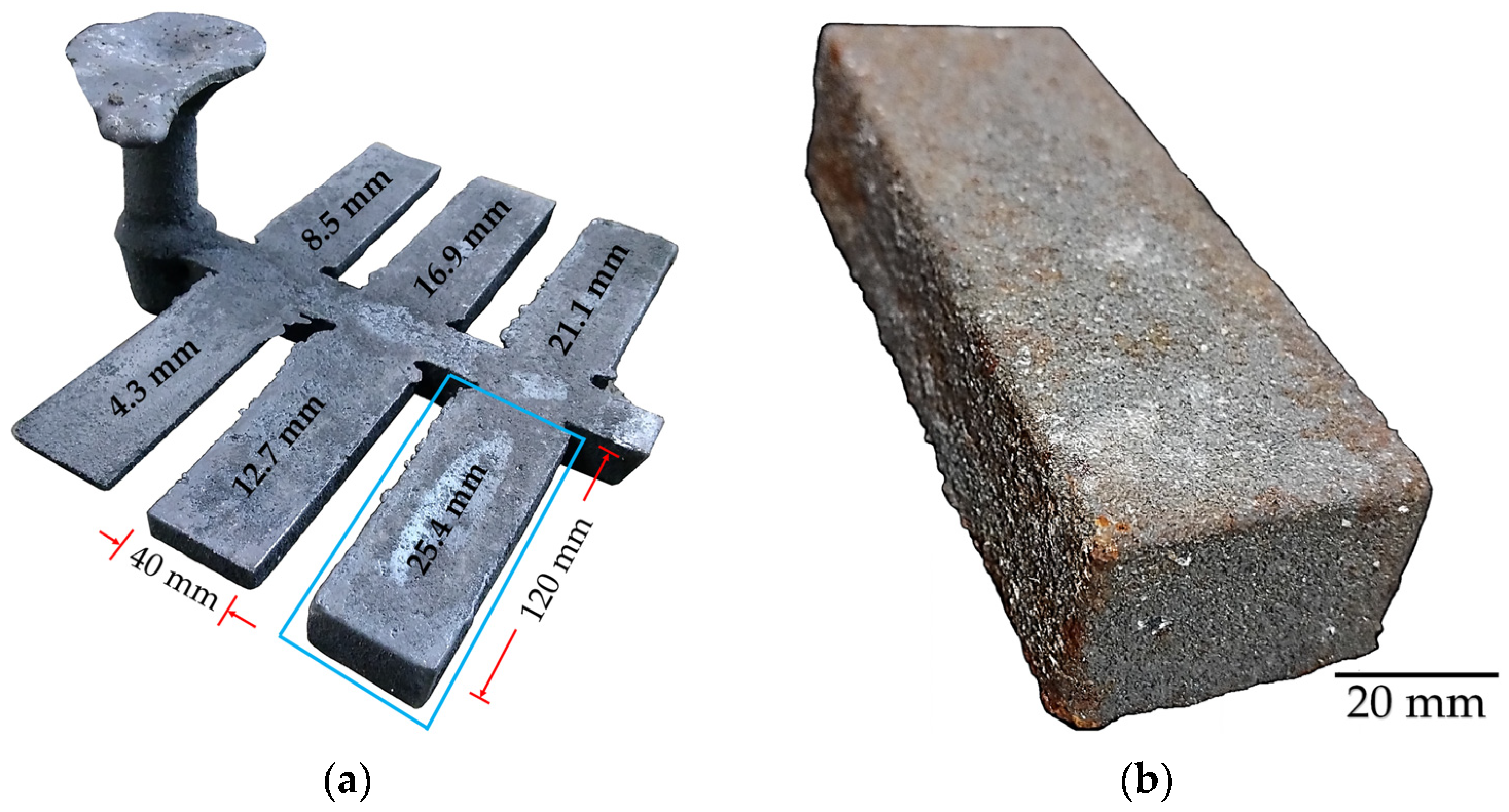
2. Materials and Methods

Two SiMo ductile irons with 0.3% Mo (DI-0.3Mo) and 0.6% Mo with 0.8% Co (DI-0.6Mo-0.8Co) were produced in a medium frequency induction furnace at 1440 °C. The raw materials used to obtain the base ductile iron were cast iron scrap, low-carbon steel, and pig iron. The chemical composition during melting metal was adjusted with FeSi, FeMo, FeMn, electrolytic cobalt, and high-purity carbon. The metal was inoculated with 1% calcifer (75% Si, 1% Ca, 0.9% Al, 1.1% Ba) in the stream from the induction furnace to the ladle, which contains 1.5% Noduloy 9C3 (45% Si, 3.3% Ca, 1.15% Al, 8% Mg, 2.8% Ce + La) covered with low-carbon steel to carry out the nodulizing by the sandwich technique. The SiMo ductile iron was poured at 1389 °C in green sand molds to obtain six casting plates with a length of 120 mm, width of 40 mm, and thicknesses of 4.3, 8.5, 12.7, 16.9, 21.1, and 25.4 mm. Figure 1 shows the casting containing plates with different thicknesses. Three castings were manufactured for each SiMo ductile iron. The plates with 25.4 mm thickness were employed to carry out microstructural and mechanical evaluations.
The nominal chemical composition for SiMo ductile irons was obtained from the average of five points selected in the cross-section using an Oxford Spark Emission Optic Spectrograph. The carbon and sulphur contents were evaluated using a Leco C/S 744 (LECO Corporation, St. Joseph, MI, USA) analyzer.

2.1. Microstructure of SiMo Ductile Irons

Conventional metallography was employed to obtain the microstructures of the SiMo ductile irons. Manual grinding was carried out with abrasive paper of grades 80, 120, 220, 320, 400, 600, and 1000. The polish was obtained employing alumina (Al2O3) of 0.3 µm and water as lubricant. The phases and microconstituents of the SiMo ductile iron were revealed by an immersion technique with the reagent nital 3%. Additionally, the SiMo ductile iron samples were etched with ammonium persulfate ((NH4)2S2O8) 10% to show the carbides contained in the metallic matrix. Ten micrographs were obtained for each plate thickness using an Olympus PMG-3 light microscope in polish and etched conditions at different magnifications.
The quantitative analysis for the nodular features of the SiMo ductile iron was carried out in micrographs on the polished condition at 100 magnification using Image J software (version 1.53K) and the area method to consider the nodularity (Equations (1) and (2)), while the average nodule size was determined with Equation 3. The quantification was carried out considering a minimum nodule size of 10 µm and sphericity of 65% [26]. The volume fraction of ferrite, pearlite, graphite, and carbides was obtained using micrographs in the etched condition with nital and ammonium persulfate at 100 magnifications.
S = 4 · π · A r e a p e r i m e t e r 2
N o d = A r e a   o f   n o d u l e   c o u n t A r e a   o f   t o t a l   p a r t i c l e s   c o u n t · 100
N S a v g = ( 2 ) ( A v · π 1 )
where S is the sphericity, Nod is the nodularity, NSavg is the average nodule size, and Av is the nodule size obtained from the Image J software.
Scanning electron microscopy (SEM) with energy dispersive spectra analysis (EDS) was carried out to evaluate the element distribution in the metallic matrix and carbides formed in the SiMo ductile iron. An SEM Jeol model 6300 was used with backscattering electrons to 25 kV and 10 A.

2.2. Hardness of SiMo Ductile Irons

Rockwell C hardness measurements were carried out in polished surface samples in the cross-section of the plates by using a Wilson 3 T TBRB hardness tester (Buehler, Lake Bluff, IL, USA) with a load of 150 kg and diamond tip based on the ASTM E 18 standard specification [27]. Ten measurements and their average and standard deviation were reported for each SiMo ductile iron.

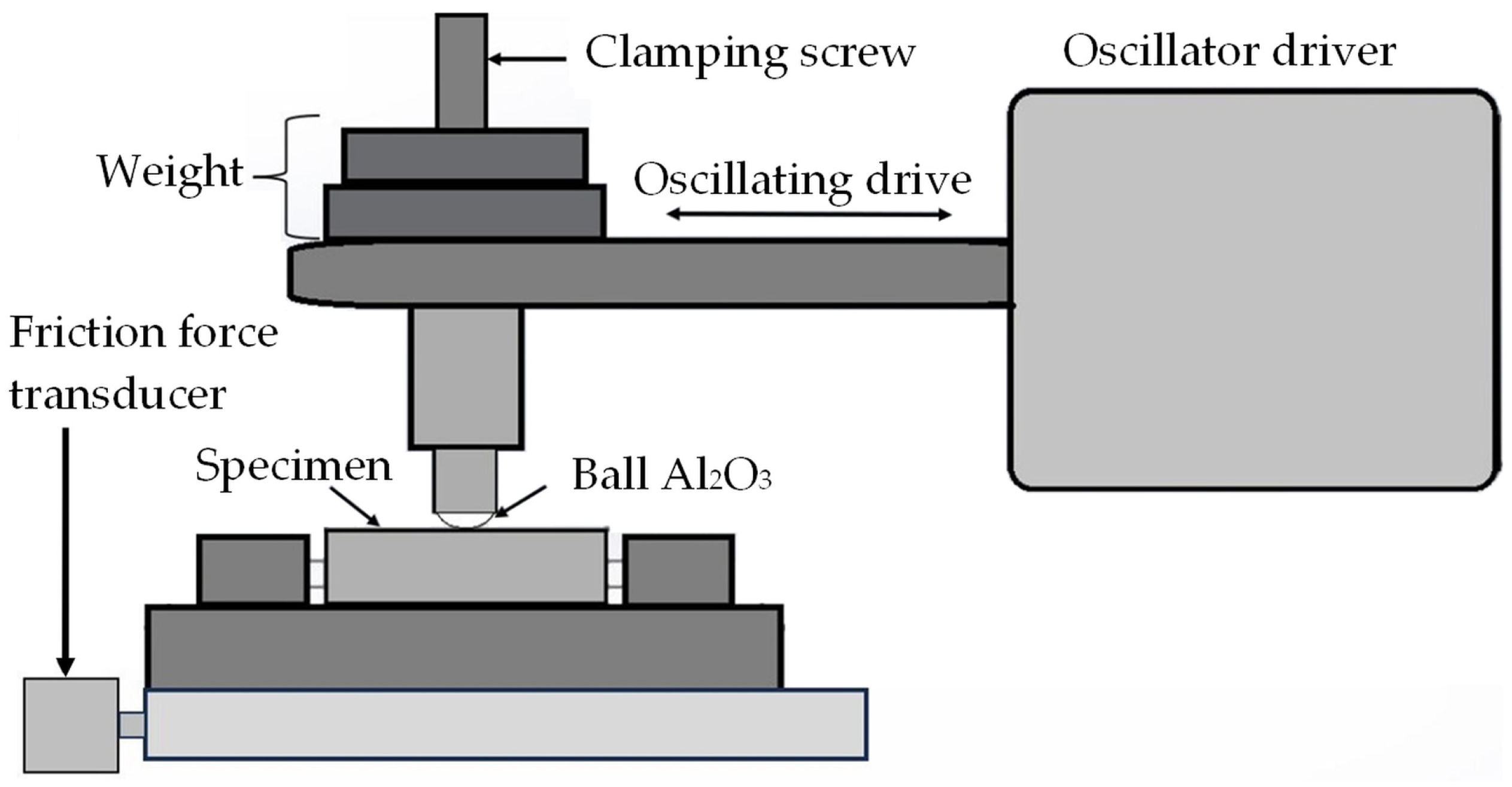
2.3. Reciprocating Sliding Wear of SiMo Ductile Irons

The dry tribological test was realized in a homemade reciprocating linear sliding machine based on procedure A reported in the ASTM G 133 standard [28,29]. However, the wear scar was not representative enough to be measured or to evaluate the material performance. Thus, it was decided to change the tribological parameters, as shown in Table 1, to generate a wear scar that could be quantitatively and qualitatively analyzed.
The samples were prepared to obtain a polished surface with an average roughness (Ra) value in a range from 0.02 to 0.05 µm. An Al2O3 ball with a diameter of 6 mm was used to slide against the flat polished sample to ensure a wear scar on the surface was defined.
The specimens and the ball were placed as shown in the schematic diagram of Figure 2.
The wear volume of the flat specimen was obtained from Equation (4), while the kinetic friction coefficient was calculated with the readings of the friction force transductor, as given in Equation (5). A computer was used to acquire data. The results are the average of three tests for each SiMo ductile iron.
V f = A × L
μ k = F P
where A is the average of the cross-sectional area of the track (mm2), L is the length of the stroke (mm), µk is the kinetic friction coefficient, F is the nominal measured friction force during sliding (N), and P is the load applied (N).

3. Results and Discussion

3.1. Chemical Composition of SiMo Ductile Irons

The chemical composition of SiMo ductile irons is shown in Table 2. The higher silicon content contributed to obtaining mainly a ferritic matrix, principally because silicon is an element that increases the ferrite content, which decreases the pearlite [30]. Manganese is an element that increases the volume fraction of pearlite [31]; hence, it was kept in low concentrations, lower than 3.0%, to avoid large regions of pearlite [15]. This is due to the high volume fraction of this microconstituent, which is undesirable SiMo ductile irons, due to instability at high temperatures. Additionally, molybdenum promotes carbide formation during solidification; in this case, it was added to low contents to obtain a low-volume fraction of carbides immersed in the metallic matrix [32]. Cobalt was added to stabilize the ferrite phase [8].

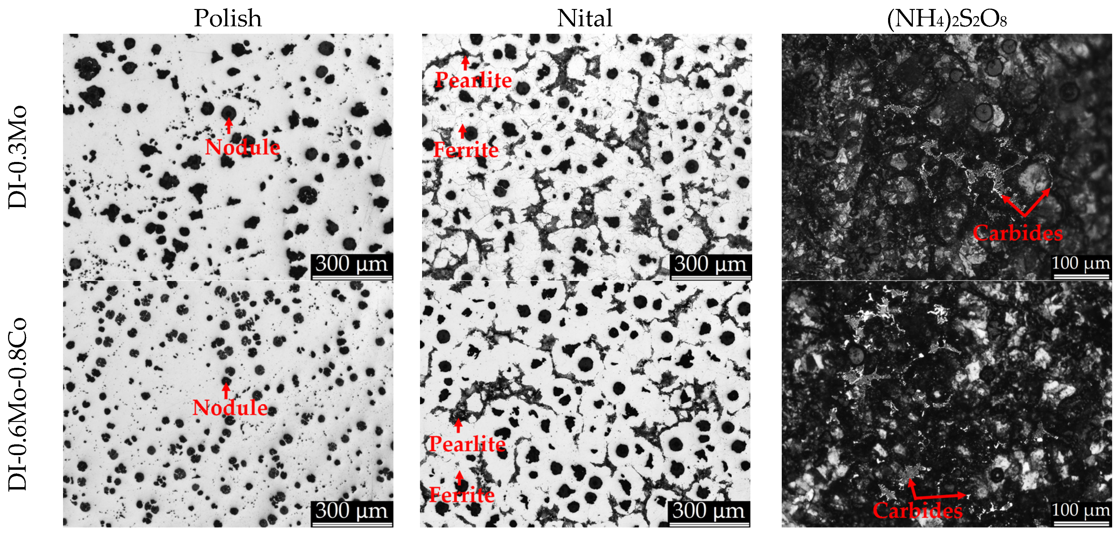
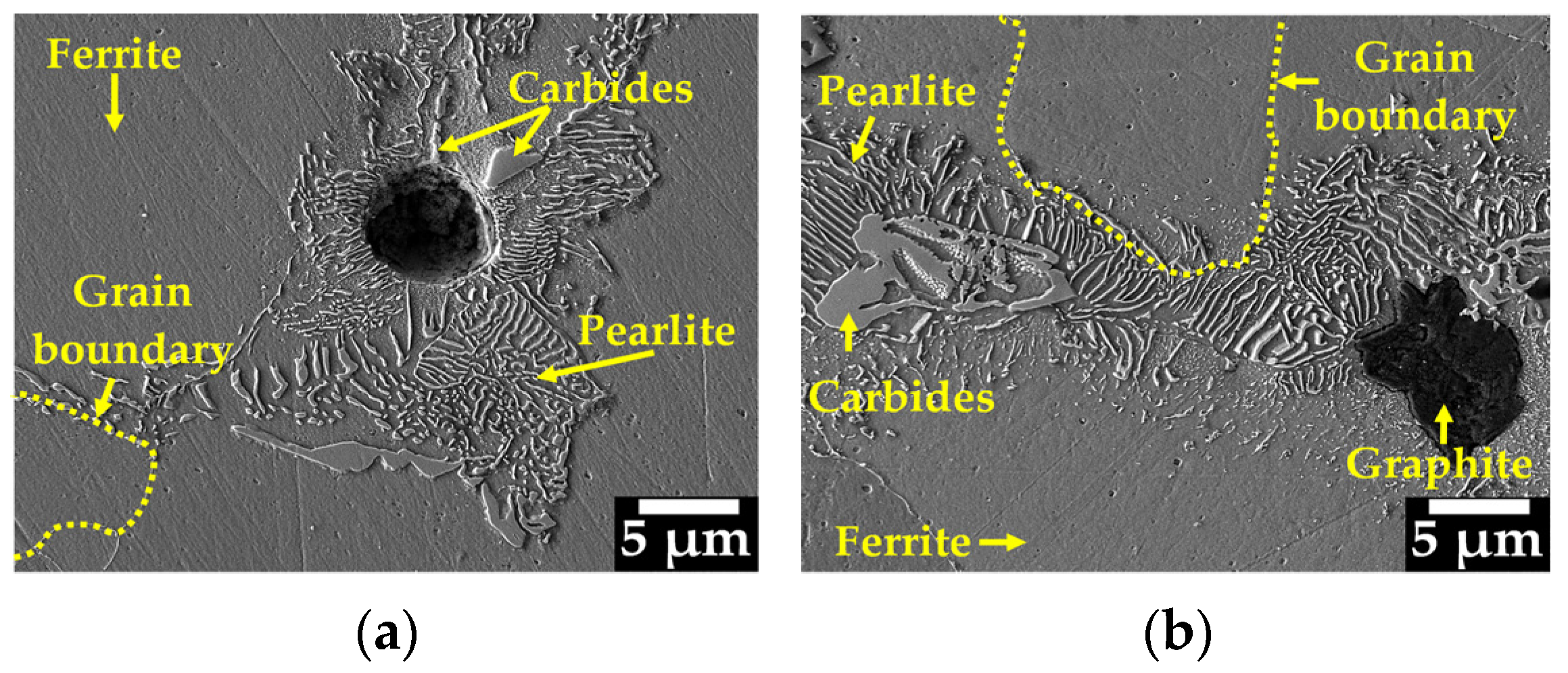
3.2. Microstructural Characterization for SiMo Ductile Irons

Figure 3 presents the micrographs of polished samples and those etched with nital and ammonium persulfate for both SiMo ductile irons. In the polished condition, both alloys exhibit well-distributed graphite nodules within the metallic matrix. A higher nodularity was observed in the sample with the highest molybdenum content combined with cobalt. The micrographs etched with nital show that ferrite is the predominant phase in the matrix, while pearlite is shown in a lower amount located in the grain boundaries; this behavior has been reported previously [33]. The micrographs etched with ammonium persulfate show carbides distributed through the metallic matrix. The microstructures obtained for the samples DI-0.3Mo and DI-0.6Mo-0.8Co match with those reported for SiMo ductile iron unalloyed and alloyed with Nb [17,18].
The quantitative analysis for nodular features and volume fraction of phases and microconstituents for SiMo ductile irons are shown in Table 3. In both ductile irons, the ferrite is the predominant phase in the matrix; this is attributed to the high silicon content in the chemical composition [30]. Silicon increases the eutectoid transformation temperature A1 in the Fe-C-Si ternary phase diagram, increasing the ferrite/austenite region [12]. The sample DI-0.3 Mo presents a volume fraction of 71.82% ferrite. In this case, molybdenum contributes to obtaining a ferrite matrix; it has been reported that molybdenum exhibits a ferritizing effect in the range of 0.1 to 0.3% during the eutectoid transformation [34]. However, the sample DI-0.6Mo-0.8Co showed the highest volume fraction of ferrite with 78.15%; this behavior was attributed to the cobalt addition. As a ferritizing element, it has been reported [8] that the cobalt addition increases the volume fraction of ferrite in the matrix, reducing the pearlite amount. Moreover, cobalt increases the nodule count [35]. This behavior is because cobalt is a graphitizing element that decreases the carbon content in the austenite during solidification [20], while silicon increases the nodule count but decreases the nodularity, and molybdenum presents a slight increment effect on nodule count for additions in the range from 0.20 to 0.27% [34].
The sample DI-0.6Mo-0.8Co contains the highest volume fraction of carbides (2.1%), attributed to the higher molybdenum content than sample DI-0.3Mo. Molybdenum acts as a carbide stabilizer and leads to carbide formation in the last to-freeze region [34], besides promoting a decrease in the eutectoid temperature at the equilibrium system [12]. It is well known that V, Cr, and Mo act as carburizing elements, increasing the volume fraction of carbides [36]. It is observed from Table 3 that the sample DI-0.6Mo-0.8Co contains almost twice the volume fraction of carbides (2.1%) than the sample DI-0.3Mo (1.4%), behavior attributed to the molybdenum content in the samples; however, it must be considered that the cobalt addition aids in avoiding the formation of the carbides during solidification. Almanza, A. [37] demonstrated that cobalt prevents the formation of carbides during solidification in SiMo ductile irons. The results obtained for graphite features and volume fraction of phases and microconstituents for the sample DI-0.3Mo are in the range reported by Górny, M. [38], who studied Si-Mo ductile irons using standard Y-Block casting.
Figure 4 shows the SEM micrographs for the DI-0.3Mo and DI-0.6Mo-0.8Co samples. It has been reported [33] that carbides contained in the metallic matrix of SiMo ductile irons are Mo6C and Mo2C types, and this last migrates to the Mo7Fe3 carbide type at high temperature. The Mo7C3 carbides have been identified from 579 to 690 °C with Thermo-Calc software [19]. In addition, a transmission electronic microscopy technique allowed the identification of the Fe2MoC carbide type, also known as Mo6C carbide, in SiMo ductile irons [39]. It is shown that carbides are located mainly inside pearlite regions at the grain boundaries, interrupting the pearlite continuity. This behavior agrees with the report in [14]. During the solidification of SiMo ductile iron, the temperature decreases; hence, the austenite nucleates and grows (L → L + γ) with the drop in temperature, and a eutectic reaction occurs where the liquid transforms into graphite and M6C carbide (L → γ + Gr + M6C) [40]. In this case, molybdenum segregates positively, accumulating in the last-to-freeze areas and promoting carbide formation during eutectic solidification [34]. During the start and end of the eutectoid reaction, some austenite decreases its stability and transforms into ferrite (γ + Gr + M6C → γ + α + G r+ M6C), and below this reaction, the nucleation and growth of pearlite surrounded by eutectic carbides is started, resulting in the formation of the cell boundary [40]. The results present an indication of M6C carbide formation in ductile irons; however, a deep analysis of the formation of eutectic carbides and the dissolution and precipitation of carbides, as well as their identification, composition, and crystal lattice, has been reported previously by Black, B. [39] and Youssef, M. [40].
Moreover, according to Figure 3 and Figure 4, the carbides of the samples of DI-0.6Mo-0.8Co show a larger size with a more homogeneous distribution through the matrix, and some of these carbides present a different morphology, such as fishbone or Chinese script [12], than that observed in the sample of DI-0.3Mo, with fine eutectic carbide morphology described previously [21]. The slow solidification rate obtained with the plate thickness of 25.4 mm contributed to obtaining larger levels of molybdenum segregation in the near vicinity of the inter-cellular zones. This results in carbides with a higher molybdenum content; hence, the morphology of the eutectic carbides is like the fishbone or Chinese script morphologies, which may contain over 45% Mo [40]. Similar carbide morphologies have been reported in ductile irons alloyed with cobalt and vanadium as carbide-forming elements. Fine carbides were observed at low vanadium concentrations, whereas increasing the vanadium content led to the formation of coarser carbides [21].
Figure 5 shows the EDS results for the matrix of the SiMo ductile iron micrographs reported in Figure 6 and Figure 7. The microanalysis presents the main peaks that correspond to the C, Si, Mo, Co, Mn, and Fe elements in both SiMo ductile irons. Moreover, the DI-0.6Mo-0.8Co sample shows two additional peaks corresponding to cobalt. The semi-quantitative analysis obtained by EDS identified the main elements reported in the chemical analysis of Table 2, which correspond to the matrix.
Figure 6 and Figure 7 show a micrograph of the metallic SiMo ductile iron sample with its X-ray mapping images for Si, Mn, Mo, C, Fe, and Co.
Figure 6 shows the results of the DI-0.3Mo sample where a ferritic matrix with a low pearlite content and three carbides surrounding a porosity are observed. Based on the distribution of the elements, the molybdenum was located principally in two carbides located at the upper part of the porosity and slightly in the matrix; hence, both carbides are attributed to molybdenum addition, whereas the carbide located at the bottom of the porosity is likely an iron carbide. The identification of iron carbide (Fe3C) has been reported in SiMo ductile irons containing less than 1% molybdenum in the matrix by X-ray diffraction measurements [41]. Additionally, silicon, iron, and manganese are homogeneously distributed throughout the metallic matrix.
The SEM micrographs of the DI-0.6Mo-0.8Co sample and the X-ray mapping analysis are shown in Figure 7. A ferritic matrix with pearlite and larger carbides is observed. Elements such as silicon, manganese, and iron are uniformly distributed throughout the matrix, while carbon is primarily concentrated in the graphite nodules. Increasing the molybdenum content up to 0.6% enhances its distribution within larger carbides and the metallic matrix. Cobalt is homogeneously distributed throughout the matrix, forming a solid solution with iron [8]. Moreover, it has been reported that higher concentrations of cobalt are located at positions where the lowest silicon concentrations are found in ductile irons alloyed with 0.4% Co. This behavior was attributed to the fact that cobalt segregates positively to intercellular boundaries between nodules, while silicon presents a negative segregation into intercellular boundaries [20].

3.3. Hardness of SiMo Ductile Irons

The average of Rockwell C hardness and its standard deviation for the SiMo ductile irons are shown in Table 4. The highest hardness value was obtained in DI-0.6Mo-0.8Co, with an average of 21.29 HRC, while the DI-0.3Mo reached an average hardness of 15.53 HRC. The difference in hardness is associated with the molybdenum content in the ductile iron. The DI-0.6Mo-0.8Co sample exhibited a higher volume fraction of molybdenum carbides, which were homogeneously distributed in pearlitic regions near the grain boundaries due to its increased molybdenum content. It has been reported [42] that an increase in the carbide amount leads to higher hardness, as carbides exhibit higher hardness compared to ferrite and pearlite, which are a softer phase and a microconstituent, respectively.
It is observed from Table 4 that there is a variation in the hardness measurements along the cross-section of the casting plates for each SiMo ductile iron. The hardness oscillations are attributed to the heterogeneity distribution of the phases and microconstituents inside the metallic matrix. In such a way, high hardness values are registered in regions closer to the grain boundaries, where there is a high amount of carbides and pearlite, whilst the large ferrite regions allow for lower hardness values. Moreover, the DI-0.3Mo sample shows lower hardness variations due to the lower amount of carbides distributed in a predominantly ferritic matrix.
It is also observed from Table 4 that the lowest registered hardness values are 10.5 HRC and 13.4 HRC for the samples DI-0.3Mo and DI-0.6-0.8Co, respectively. The lowest hardness values are associated with the presence of large regions of soft ferrite, which is the predominant phase in the matrix. Both SiMo ductile irons contain a similar silicon content, which slightly increases the ferrite fraction due to its role as a solid-solution strengthening element [43]. The hardness difference in both ductile irons is attributed to the high molybdenum and cobalt [34], which are homogeneously distributed in the ferritic matrix, acting as solid-solution strengthening elements [22,23] and increasing the ductile iron strength, as observed in Figure 7. The increase in the molybdenum content aids in increasing the ductile iron hardness because of the higher amount of molybdenum carbides formed. A similar behavior was reported by Chavan, S. [33], where Brinell hardness values of 175 to 230 BHN were obtained for SiMo ductile irons containing up to 0.8% Mo.

3.4. Reciprocating Sliding Wear of SiMo Ductile Irons

The SiMo ductile irons evaluated contain a high nodule count (175–247 Nod/mm2) with an optimum nodularity (80–86%) distributed in a predominantly ferritic matrix. The free graphite nodules act as a lubricant and avoid the formation of cracks; as a result, the tribological properties improve [44]. For this reason, the reciprocating ball-on-flat sliding wear test was carried out without the use of lubricant. Figure 8 shows the SiMo ductile iron results on the volume loss due to the reciprocating ball-on-flat sliding wear and Rockwell C hardness.
The highest wear resistance was obtained for the DI-0.6Mo-0.8Co sample, which shows the lower volume loss (3.78 mm3), which is related to its large volume fraction of carbides in a ferritic matrix reinforced by cobalt addition. The larger size of carbides and fishbone or Chinese script morphology in DI-0.6Mo-0.8Co presents more resistance to wear because they are more strongly alloyed with molybdenum (over 45%) [40] than those fine carbides attributed to molybdenum or cementite in the DI-0.3Mo sample. In addition, the sample DI-0.6Mo-0.8Co presents the highest hardness, which increases the wear resistance [36,42]. Despite the higher volume fraction of ferrite, this phase presents a strengthening of the α-solution solid due to silicon [43], molybdenum [34], and cobalt [22,23] atoms, which substitute iron atoms in the crystal lattice. This substitution distorts the lattice, hindering dislocation movement during deformation and thereby requiring higher stresses to initiate dislocation motion [43]; therefore, higher stresses are needed to start the dislocation movement through the crystal lattice [36]. A similar behavior on wear resistance at room temperature was reported by Abdelrahim, D. [12], who showed that by increasing the hardness in SiMo ductile irons due to a larger amount of carbides, the wear resistance increases.
Figure 9 shows the wear scars obtained from the wear test for the SiMo ductile irons. The DI-0.3Mo sample shows the highest width and depth scar. The red, green, and blue lines show depth values corresponding to −109.26, −146.36, and −80 µm, which are related to width values of 1.28, 1.32, and 1.14 mm, respectively. These results indicate that larger depth and width scars were obtained when the SiMo ductile iron contains a low volume fraction of carbides and the matrix is principally ferrite. The graphics will have an upward concave curve without sharp edges, maintaining the width and depth alike. On the contrary, the sample DI-0.6Mo-0.8Co shows the lowest width and depth scar; this behavior was attributed to a higher volume fraction of carbides, which increases the wear resistance. The curves present a serrate shape, which indicates that the matrix is not wearing equitably in the width and depth address, and some areas are wearing more than others.
Figure 10 shows the kinetic friction coefficient (µk) results for the SiMo ductile irons evaluated. The samples DI-0.3Mo and DI-0.6Mo-0.8Co show a friction coefficient from around 0.053 to 0.20 and from 0.053 to 0.045, respectively. It is observed that the DI-0.3Mo sample shows larger variations of the friction coefficient obtained during the wear testing. Due to the heterogeneity of the matrix, the µk shows an increment when the force is applied to the ferrite region and decreases in the carbide regions. On the other hand, the sample DI-0.6Mo-0.8Co, which presents the highest volume fraction of molybdenum carbides in a reinforced ferritic matrix by cobalt addition, shows a lower friction coefficient with homogeneous behavior. Thus, a high kinetic friction coefficient results in a larger volume loss and a low wear resistance. The results match with those reported by Abdelrahim, D. [12], who evaluated SiMo ductile irons in a ball-on-disc wear test at different temperatures. The friction coefficient was increased as the mass loss was increased in the ductile iron samples.

4. Conclusions

The effects of molybdenum and cobalt additions on the microstructure, hardness, and reciprocating sliding wear behavior of SiMo ductile irons were evaluated, leading to the following conclusions:
  • The addition of 0.6% Mo and 0.8% Co in the ductile iron improves the nodule count with 247 nod/mm2, the nodule size is refined with 22.32 µm and 86.69% nodularity, and there is an increase in the volume fraction of ferrite with 78.15% and carbides of 2.1%.
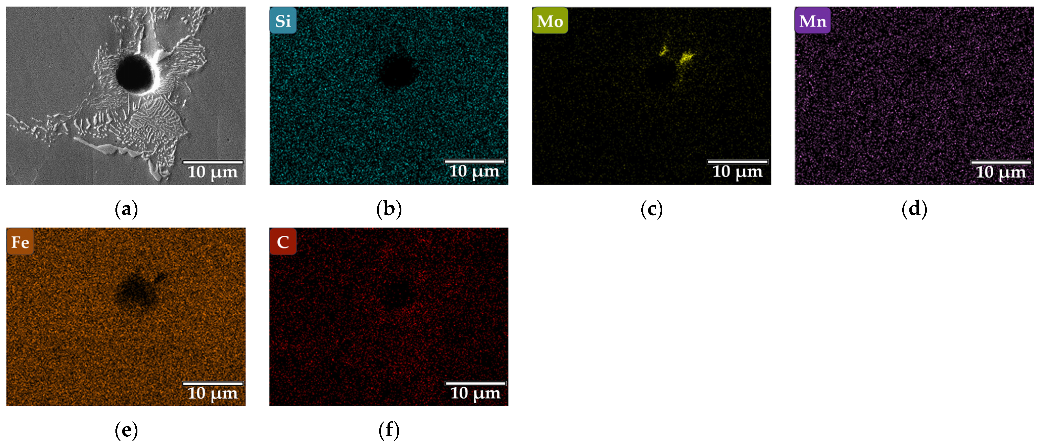
  • The carbides due to molybdenum addition were located in the pearlite microconstituent in the grain boundaries inside the predominantly ferritic matrix.
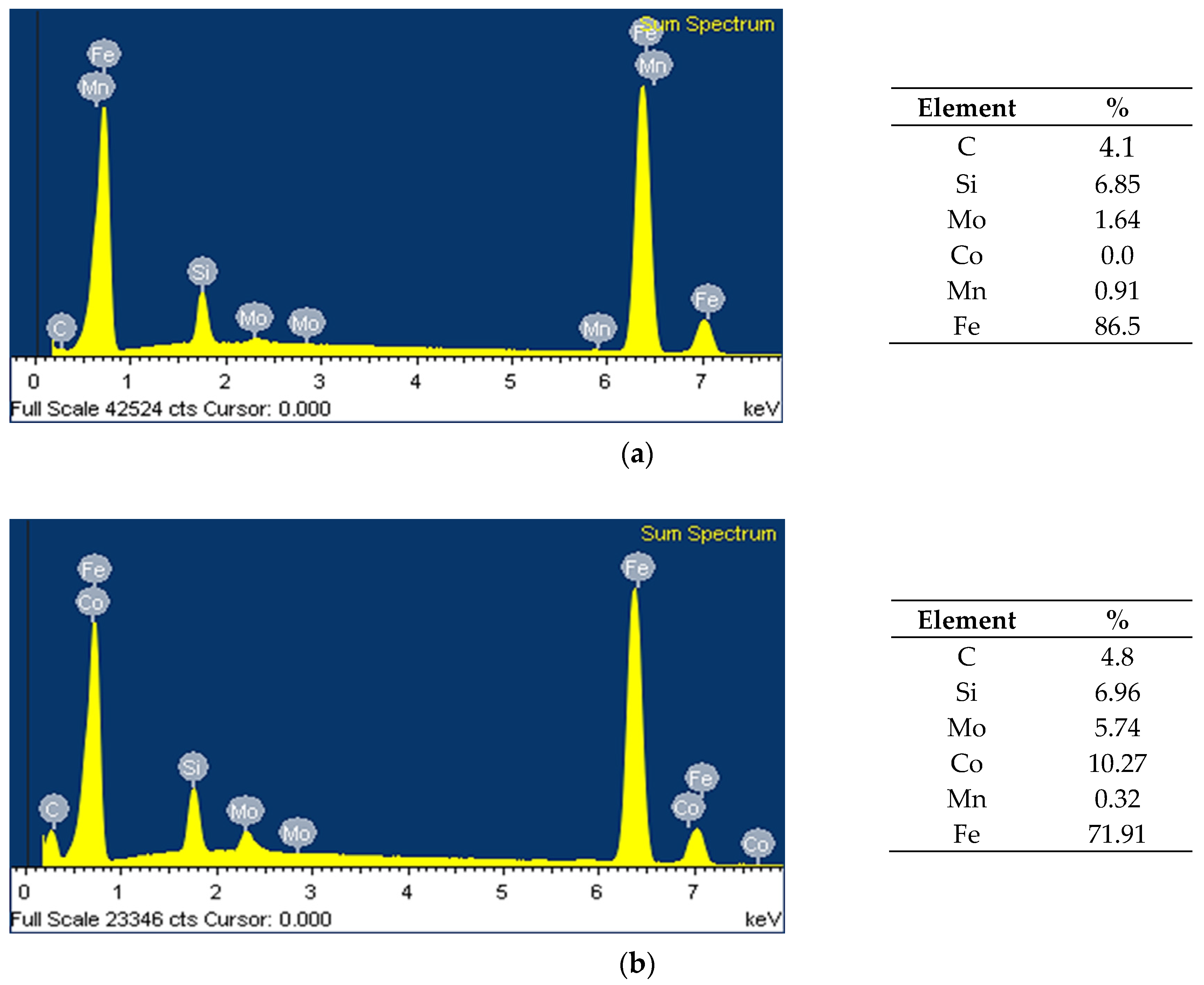
  • The SiMo ductile irons were evaluated to show that molybdenum was mainly distributed in the carbides, while cobalt was distributed homogeneously in the ferritic matrix, increasing its strength.
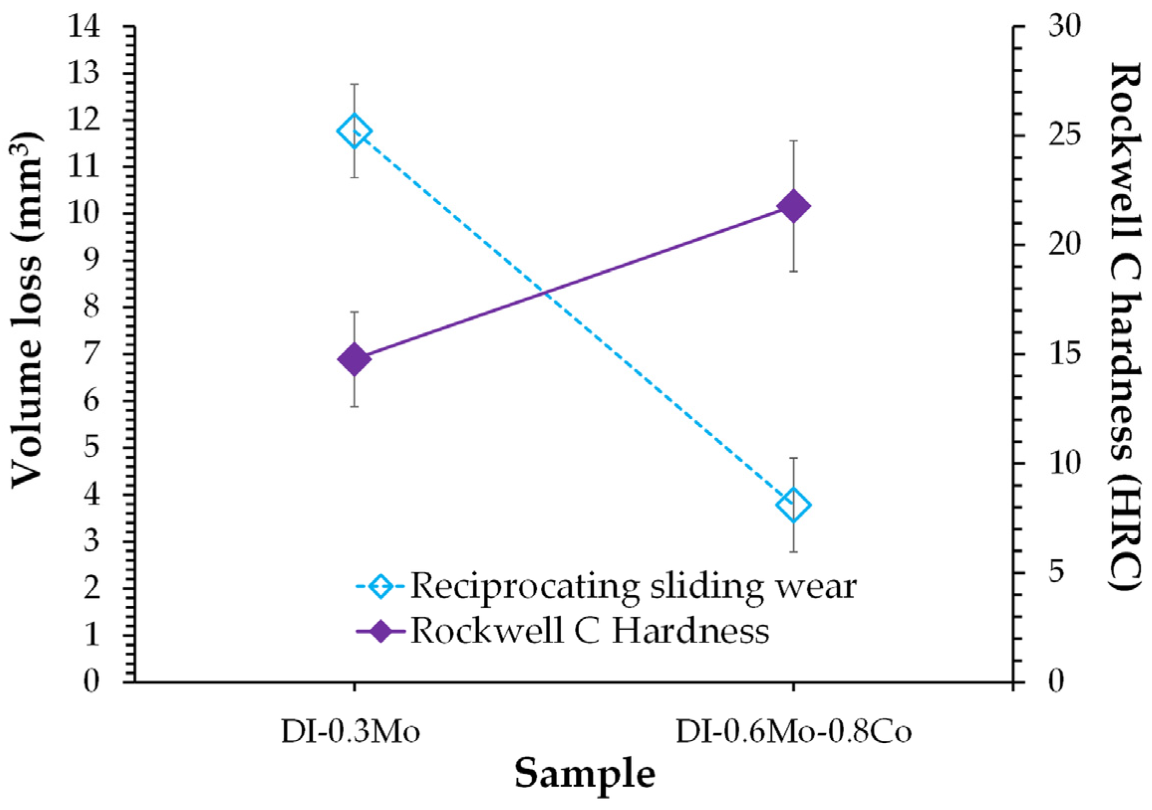
  • The highest Rockwell C hardness (21.29 HRC) was obtained for the SiMo ductile iron containing 0.6% Mo and 0.8% Co due to the highest carbide content (2.1%).
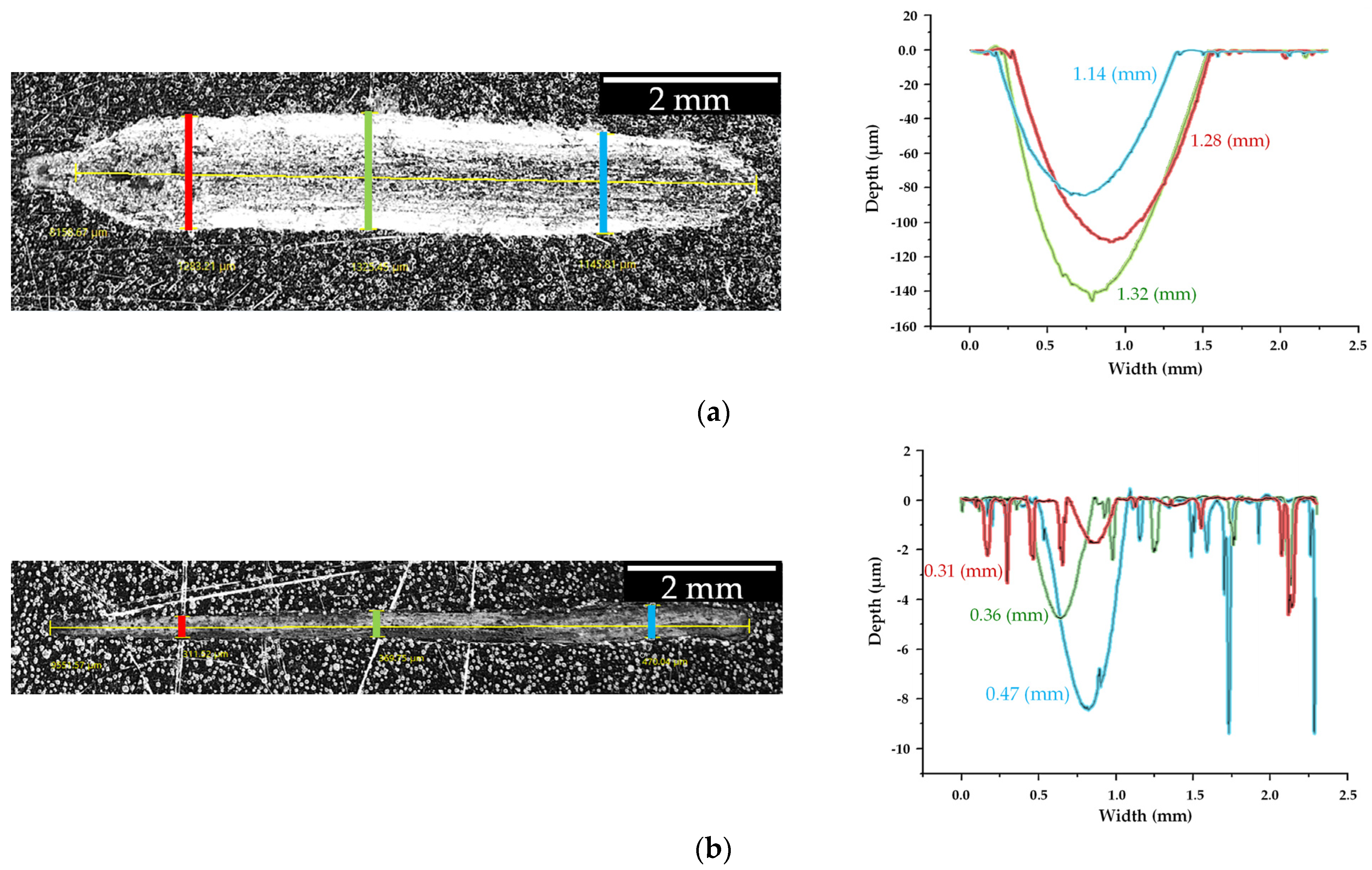
  • The highest wear resistance due to the lower volume loss (3.78 mm3) and the low friction coefficient was obtained for the SiMo ductile iron containing 0.6% Mo and 0.8% Co as a result of the increased strength of the ferritic matrix by cobalt addition and high carbide content.
  • The addition of 0.8% cobalt and 0.6% molybdenum in the SiMo ductile iron contributed to obtaining a higher amount of ferrite (78.15%) with high strength due to a solid-solution mechanism with Co and Mo; this last element also contributed to forming a higher volume fraction of molybdenum carbides (2.1%) with appropriate dispersion in the grain boundaries closer to pearlite regions. Both features contributed to obtaining a higher hardness (21.29 HRC) and higher wear resistance.

Author Contributions

Conceptualization, E.C.-G. and E.E.V.-C.; data curation, R.G.S.-A. and J.C.J.-L.; formal analysis, E.C.-G., M.M.-R., A.I.M.-P. and E.E.V.-C.; funding acquisition, A.C.-R.; investigation, E.C.-G., M.M.-R. and J.A.R.-S.; methodology, M.M.-R., R.G.S.-A., J.C.J.-L. and A.I.M.-P.; software, J.A.R.-S.; supervision, A.C.-R.; visualization, E.C.-G.; writing—original draft, E.C.-G.; writing—review and editing, E.C.-G. and A.C.-R. All authors have read and agreed to the published version of the manuscript.

Funding

This research received no external funding.

Data Availability Statement

Data are contained within the article. Further inquiries can be directed to the corresponding author.

Acknowledgments

The authors wish to thank the institutions of CONAHCyT, Estancias postdoctorales por México, SNII, COFAA, and SIP-Instituto Politécnico Nacional for their permanence assistance to the Process Metallurgy Group at ESIQIE-Metallurgy and Materials Department.

Conflicts of Interest

The authors declare no conflicts of interest.

References

  1. Sirtuli, L.J.; Bermejo, J.M.B.; Windmark, C.; Norgren, S.; Ståhl, J.-E.; Boing, D. Machining of compacted graphite iron: A review. J. Mater. Proces. Tech. 2024, 332, 118553. [Google Scholar] [CrossRef]
  2. Chen, T.; Wang, C.; Yan, C.; Li, F.; Wang, J.; Wang, J. Study on friction and wear behavior of gray cast iron with different carbon content at different temperatures. Mater. Res. Express 2024, 11, 046505. [Google Scholar] [CrossRef]
  3. Hu, Z.; Liu, C.; Du, Y.; Wang, X.; Zhu, X. Effects of tempering temperature on mechanical and tribological behavior of ductile iron. Lubricants 2022, 10, 326. [Google Scholar] [CrossRef]
  4. Oktadinata, H.; Latifah, S.M.; Sastrawan, S. Influence of tempering time on the microstructure, hardness and impact toughness of ductile cast iron. In Proceedings of the 6th Mechanical Engineering, Science and Technology International Conference (MEST 2022), Xiamen, China, 21–23 October 2022; Atlantis Press: Paris, France, 2023. [Google Scholar]
  5. Machado, H.D.; García-Mateo, C.; Aristizábal-Sierra, R. Effect of intercritical austenitization and starting matrix on martensite start temperature and austenite carbon concentration in ductile iron. Inter. J. Met. 2024, 1–11. [Google Scholar] [CrossRef]
  6. Colin-García, E.; Cruz-Ramírez, A.; Reyes-Castellanos, G.; Romero-Serrano, J.A.; Sánchez-Alvarado, R.G.; Hernández-Chávez, M. Influence of nickel addition and casting modulus on the properties of hypo-eutectic ductile cast iron. J. Min. Metall. Sect. B-Metall. 2019, 55, 283–293. [Google Scholar] [CrossRef]
  7. Ješić, D.; Kovač, P.; Plavšić, M.; Šooš, L.; Sarjanović, D. Wear resistance of austempered pearlitic ductile iron. Kov. Mater. 2018, 56, 415–418. [Google Scholar]
  8. Hsu, G.H.; Chen, M.L.; Hu, C.J. Microstructure and mechanical properties of 4% cobalt and nickel alloyed ductile irons. Mater. Sci. Eng. A 2007, 444, 339–346. [Google Scholar] [CrossRef]
  9. Guerra, F.; Bedolla-Jacuinde, A.; Mejia, I.; Zuno, J.; Maldonado, C. Effects of boron addition and austempering time on microstructure, hardness and tensile properties of ductile irons. Mater. Sci. Eng. A 2015, 648, 193–201. [Google Scholar] [CrossRef]
  10. Hegde, A.; Anne, G.; Gowrishankar, M.C.; Sharma, S.; Karthik, B.M.; Castelino, M.R. Effect of austempering parameters and manganese content on the machinability of austempered ductile iron produced using novel method. Cogent. Eng. 2024, 11, 1–10. [Google Scholar] [CrossRef]
  11. Dakre, V.S.; Peshwe, D.R.; Pathak, S.U.; Likhite, A.A. Characterization of austempered ferritic ductile iron. Mater. Sci. Eng. 2018, 346, 1–10. [Google Scholar] [CrossRef]
  12. Abdelrahim, D.M.; Ateia, E.E.; Nofal, A.A. Effect of molybdenum contents on microstructure and high-temperature wear behavior of SiMo ductile iron. Int. J. Met. 2024, 18, 530–545. [Google Scholar] [CrossRef]
  13. Lekakh, S.N.; Bofah, A.; Godlewski, L.A.; Li, M. Effect of micro-structural dispersity of SiMo ductile iron on high temperature performance during static oxidation. Metals 2022, 12, 661. [Google Scholar] [CrossRef]
  14. Hervas, I.; Thuault, A.; Hug, E. Damage analysis of a ferritic SiMo ductile cast iron submitted to tension and compression loadings in temperature. Metals 2015, 5, 2351–2369. [Google Scholar] [CrossRef]
  15. Roučka, J.; Abramová, E.; Kaňa, V. Properties of type SiMo ductile irons at high temperatures. Arch. Metall. Mater. 2018, 63, 601–607. [Google Scholar] [CrossRef]
  16. Stawarz, M. SiMo ductile iron crystallization process. Arch. Foundry Eng. 2017, 17, 147–152. [Google Scholar] [CrossRef]
  17. de Magalhães, M.M.; Lemos, G.V.B.; Froehlich, A.; Piaggio, H.; Clarke, T.; Reguly, A. Microstructure and mechanical properties of SiMo ductile cast irons alloys with varied Mo and Nb contents. J. Mater. Res. Technol. 2024, 30, 6301–6308. [Google Scholar] [CrossRef]
  18. Stan, I.; Chisamera, M.; Lascu, R.; Cariga, C.; Stefan, E.; Stan, S.; Anca, D.; Riposan, L. High temperature oxidation of inoculated high Si/SiMo ductile cast irons in air and combustion atmospheres. China Foundry 2024, 21, 555–562. [Google Scholar] [CrossRef]
  19. Dyrlaga, Ł.; Zapała, R.; Morgiel, K.; Studnicki, A.; Szczęsny, A.; Kopyciński, D. Evaluation of microstructure and abrasive wear-resistance of medium alloy SiMo ductile cast iron. Materials 2024, 17, 1223. [Google Scholar] [CrossRef]
  20. Yazdani, S.; Bayati, H.; Elliot, R. The influence of the cobalt on the austempering reaction in ductile cast iron. Int. J. Cast. Metals Res. 2001, 13, 317–326. [Google Scholar] [CrossRef]
  21. Shen, X.P.; Harris, S.J.; Noble, B. Influence of small vanadium and cobalt additions on microstructure and properties of ductile iron. Mater. Sci. Tech. 1995, 11, 893–900. [Google Scholar]
  22. Duwe, S.; Tonn, B. Ductile cast iron with high toughness at low temperatures. Mater. Sci. Forum 2018, 925, 334–341. [Google Scholar] [CrossRef]
  23. González-Martínez, R.; Sertucha, R.J.; Lacaze, J. Effects of cobalt on mechanical properties of high silicon ductile irons. Mater. Sci. Technol. 2020, 36, 327–333. [Google Scholar] [CrossRef]
  24. Yiran, W.; Ruian, W.; Yimin, G. Effect of Co content on microstructure and mechanical properties of maraging steel. J. Mater. Res. Technol. 2023, 27, 3887–3899. [Google Scholar] [CrossRef]
  25. Almanza, A.; Dewald, D.; Licavoli, J.; Sanders, P.G. Influence of cobalt in the tensile properties of 1/2 inch ductile iron Y-blocks mold. Inter. Met. 2021, 15, 443–446. [Google Scholar]
  26. Colin-García, E.; Sánchez-Alvarado, R.G.; Cruz-Ramírez, A.; Suarez-Rosales, M.A.; Portuguez-Pardo, L.; Jiménez-Lugos, J.C. Effect of regular thicknesses on the microstructural and quantitative analysis for a hypo-eutectic ductile iron alloyed with Ni and V. J. Min. Metall. Sect. B-Met. 2024, 60, 15–31. [Google Scholar] [CrossRef]
  27. ASTM E 18; Standard Test Methods for Rockwell Hardness of Metallic Materials. ASTM International ASTM International: West Conshohocken, PA, USA, 2002.
  28. ASTM G 133; Standard Test Method for Linearly Reciprocating Ball-on-Flat Sliding Wear. ASTM International: West Conshohocken, PA, USA, 2005.
  29. Ortiz-Armenta, M.A.; Vera-Cárdenas, E.E.; Abundis-Fong, H.F.; Martínez-Pérez, A.I. Diseño, análisis y fabricación de una plataforma para pruebas de desgaste. In Proceedings of the XXVIII Congreso Internacional Anual de la SOMIM, Bogotá, Colombia, 22 September 2022. [Google Scholar]
  30. Arshad, W.; Mehmood, A.; Hashmi, M.F.; Rauf, O.U. The effect of increasing silicon on mechanical properties of ductile iron. J. Phys. Conf. Ser. 2018, 1082, 1–6. [Google Scholar] [CrossRef]
  31. Omran, A.M.; Abdel-Jaber, G.T.; Ali, M.M. Effect of Cu and Mn on the mechanical properties and microstructure of ductile cast iron. J. Eng. Res. Appl. 2014, 4, 90–96. [Google Scholar]
  32. Upadhyay, S.; Saxena, K.K. Effect of Cu and Mo addition on mechanical properties and microstructure of grey cast iron: An overview. Mater. Today Proc. 2020, 26, 2462–2470. [Google Scholar] [CrossRef]
  33. Chavan, S.; Khandelwal, H. Effect of Mo on micro-structural and mechanical properties of as-Cast ferritic spheroidal graphite iron. Trans. Indian Inst. Met. 2021, 74, 2703–2711. [Google Scholar] [CrossRef]
  34. Franzen, D.; Pustal, B.; Bührig-Polaczek, A. Mechanical properties and impact toughness of molybdenum alloyed ductile iron. Inter. Met. 2021, 15, 983–994. [Google Scholar] [CrossRef]
  35. Sadighzadeh, B.A. Effect of alloying elements on austempered ductile iron (ADI) properties and its process: Review. China Foundry 2015, 1, 54–70. [Google Scholar]
  36. Han, C.F.; Sun, Y.F.; Wu, Y.; Ma, Y.H. Effects of vanadium and austempering temperature on microstructure and properties of CADI. Metallogr. Microstruct. Anal. 2015, 4, 135–145. [Google Scholar] [CrossRef]
  37. Almanza, A.I. Effect of Cobalt in Thin Wall Ductile Iron and Solid Effect of Cobalt in Thin Wall Ductile Iron and Solid Solution Strengthened Ferritic Ductile Iron. Ph.D. Thesis, Michigan Technological University, Houghton, MI, USA, 2020. [Google Scholar]
  38. Górny, M.; Kawalec, B.M.; Gracz, B.; Tupaj, M. Influence of cooling rate on microstructure formation of Si–Mo ductile iron castings. Metals 2021, 11, 1634. [Google Scholar] [CrossRef]
  39. Black, B.; Burger, G.; Logan, R.; Perrin, R.; Gundlach, R. Microstructure and dimensional stability in Si-Mo ductile irons for elevated temperature applications. SAE Tech. 2002, 1, 1–18. [Google Scholar]
  40. Youssef, M.; Nofal, A.; Hussein, A. Influence of cooling rate on nature and morphology of intercellular precipitates in Si-Mo ductile irons. Mater. Sci. Forum 2018, 925, 231–238. [Google Scholar] [CrossRef]
  41. Stawarz, M. The Role of Intermetallic Phases in Silicon Cast Iron; Polish Academy of Sciences: Katowice, Poland, 2019. [Google Scholar]
  42. Cruz Ramírez, A.; Colin García, E.; Chávez Alcalá, J.F.; Téllez Ramírez, J.; Magaña Hernández, A. Evaluation of CADI Low Alloyed with Chromium for Camshafts Application. Metals 2022, 12, 249. [Google Scholar] [CrossRef]
  43. Glavas, Z.; Strkalj, A.; Stojakovic, A. The properties of silicon alloyed ferritic ductile irons. Metalurgija 2016, 55, 293–296. [Google Scholar]
  44. Meza-Salazar, G.; Cruz-Manjarrez, H.; Agredo-Diaz, G.D.; Ortiz-Godoy, N.; Rickards-Campbell, J.; González-Parra, R.; Valdez-Navarro, R.; Barba-Pingarrón, A. Surface modification of a ferritic ductile iron through plasma nitriding. Dyna 2021, 88, 203–209. [Google Scholar] [CrossRef]
Figure 1. Casting containing the six plates with different thicknesses: (a) casting and (b) plate thickness of 25.4 mm.
Crystals 15 00278 g001
Figure 2. Schematic diagram of the linear reciprocating wear machine.
Crystals 15 00278 g002
Figure 3. Micrographs for SiMo ductile irons on polished samples, as well as those etched with nital and ammonium persulfate conditions.
Crystals 15 00278 g003
Figure 4. SEM micrographs for SiMo ductile irons: (a) DI-0.3Mo and (b) DI-0.6Mo-0.8Co.
Crystals 15 00278 g004
Figure 5. X-ray spectrum and semi-quantitative analysis for SiMo ductile iron: (a) DI-0.3Mo and (b) DI-0.6Mo-0.8Co.
Crystals 15 00278 g005
Figure 6. SEM image (a) and X-ray mapping for the sample DI-0.3Mo to (b) silicon, (c) molybdenum, (d) manganese, (e) iron, and (f) carbon.
Crystals 15 00278 g006
Figure 7. SEM image (a) and X-ray mapping for the sample DI-0.6Mo-0.8Co to (b) silicon, (c) molybdenum, (d) manganese, (e) iron, (f) carbon, and (g) cobalt.
Crystals 15 00278 g007
Figure 8. Wear resistance and Rockwell C hardness for the DI-0.3Mo and DI-0.6Mo-0.8Co samples.
Crystals 15 00278 g008
Figure 9. Wear scars for (a) DI-0.3Mo and (b) DI-0.6Mo-0.8Co samples.
Crystals 15 00278 g009
Figure 10. Effect of molybdenum and cobalt on the friction coefficient.
Crystals 15 00278 g010
Table 1. Parameters for tribology testing.
Test ParameterValue
Hertz pressure (GPa)2.11
Load (N)30
Frequency (Hertz)4
Amplitude (mm)9
Total sliding distance (m)86.4
Test duration (s)1800
Table 2. Chemical composition for SiMo ductile irons (%).
SampleCSiMnPSMgMoCoNiAlCuNbVCE
DI-0.3Mo3.583.760.200.0090.0020.0380.330.00.10.10.10.020.014.86
DI-0.6Mo-0.8Co3.513.830.220.0040.0030.0360.610.820.10.10.10.010.014.78
Balance Fe; where C E c a r b o n   e q u i v a l e n t = % C + % S i + % P 3 .
Table 3. Quantitative analysis for graphite features and phases of SiMo ductile irons.
SampleNodule Count (Nod/mm2)Nodule Size (µm)Nodularity (%)Graphite (%)Ferrite (%)Pearlite (%)Carbides (%)
DI-0.3Mo17530.9580.1413.8871.8212.81.4
DI-0.6Mo-0.8Co24722.3286.6911.4278.158.322.1
Table 4. Rockwell C hardness for SiMo ductile irons.
SampleRockwell C Hardness MeasurementsAverage
12345678910
DI-0.3Mo20.115.316.417.215.214.614.514.716.810.515.53 ± 2.45
DI-0.6Mo-0.8Co21.620.324.537.513.42915.318.414.219.721.29 ± 7.39
Disclaimer/Publisher’s Note: The statements, opinions and data contained in all publications are solely those of the individual author(s) and contributor(s) and not of MDPI and/or the editor(s). MDPI and/or the editor(s) disclaim responsibility for any injury to people or property resulting from any ideas, methods, instructions or products referred to in the content.

