1. Introduction
Iron-based metallic powders form the foundation of numerous high-tech industries, including additive manufacturing [
1], powder metallurgy [
2], the development of soft magnetic composites [
3,
4], fabrication of anodes for metal-ion batteries [
5,
6], and catalyst synthesis [
7]. The key factors determining the applicability of the final product are the morphology, particle size distribution, chemical purity, and microstructure of powder particles. These characteristics directly depend on the synthesis method, which drives the continuous search for and improvement of techniques for producing metallic powders with tailored properties. The traditional and widely industrially used methods for producing metallic powders include melt atomization (gas [
8] and water [
9]), mechanical alloying and milling [
10,
11], calciothermic reduction of oxides [
12], electrolysis from aqueous solutions [
13], and the carbonyl process [
14]. Despite their high productivity, atomization techniques require significant energy input and complex equipment, while the resulting spherical particles may exhibit suboptimal compressibility [
8,
9]. Mechanical methods often result in product contamination by the material of the milling media and the introduction of defects into the particle structure [
10]. Chemical metallurgical processes, such as reduction, may be associated with issues of residual porosity and oxygen contamination [
12].
In this context, electrolyte–plasma processing (EPP), also known as electrolyte–plasma synthesis (EPS), of powders represents a highly efficient alternative approach [
15,
16]. This method is based on the phenomenon of localized anodic dissolution of a metallic workpiece in an electrolyte under the action of high-density pulsed or direct current, which leads to the formation of a stable plasma sheath (vapor phase) around the electrode. The intense thermal effect of the plasma and the subsequent rapid cooling of micro-amounts of material in the electrolyte volume initiate phase transformations, crystallization, and the formation of ultradispersed particles [
17,
18]. The key advantages of the electroplasma method (EPM) include the following: high process productivity and energy efficiency [
19]; the ability to produce powders of both pure metals and alloys of a specified chemical composition, including refractory metals and intermetallics, through the choice of anode material [
20]; unique control over particle morphology (spherical, needle-like, flake-like) by varying process parameters such as current density and electrolyte composition [
21,
22]; high product purity [
23]; and relatively simple and cost-effective equipment [
24]. Comparative analysis shows that the EPM successfully competes with traditional techniques, particularly in terms of flexibility in controlling powder properties and the cost-effectiveness of the process for medium- and small-scale production of specialty materials [
25,
26].
A more detailed examination of the EPM reveals its physico-chemical essence. The process takes place in an electrochemical cell, where the metal being processed serves as the anode. When the critical current density (~10
5–10
7 A/m
2) is reached at the metal–electrolyte interface, intensive vaporization and ionization of both the electrolyte vapors and the anode material occur, leading to the formation of a plasma sheath [
27,
28]. The temperature in the discharge zone can reach 5000–10,000 K, which ensures melting, dispersion, and subsequent rapid crystallization of the metal surface layer [
29]. The detachment and condensation of molten microdroplets in the cooled electrolyte volume lead to the formation of spherical particles, while electrochemical dissolution and subsequent reduction of ions may result in the formation of dendritic or irregularly shaped particles [
30,
31]. The most important technological parameters governing the process are the following: the composition, concentration, temperature, and pH of the electrolyte; the anode material; the current density; the duration and duty cycle of the voltage pulses; and the geometry of the interelectrode gap [
32,
33]. Numerous research studies have been devoted to a comprehensive analysis of powders synthesized by the electroplasma method. Studies using scanning electron microscopy (SEM) and transmission electron microscopy (TEM) confirm that the method makes it possible to obtain iron and iron-alloy powders with a wide range of particle sizes (from nanometers to several tens of micrometers) and complex morphologies [
34,
35]. X-ray diffraction (XRD) and energy-dispersive X-ray spectroscopy (EDS) demonstrate the possibility of forming not only pure α-Fe but also various oxide (Fe
3O
4, γ-Fe
2O
3) and nitride phases on the particle surface, which can be purposefully utilized for the design of functional core–shell structures [
36,
37,
38]. Studies of the magnetic properties have shown that iron-based powders obtained by the electroplasma method exhibit competitive coercivity and saturation magnetization characteristics, which opens up prospects for their application in soft magnetic composites [
39,
40]. In addition, the catalytic activity of such powders has been studied, for example, in hydrogen peroxide decomposition reactions [
41], as well as their electrochemical performance as anode materials for sodium-ion batteries [
42].
The aim of this work is to systematically investigate the influence of key technological parameters of the electroplasma process (processing regimes, electrolyte composition, and the nature of alloying additives) on morphology, phase composition, and particle size distribution.
2. Materials and Methods
Steel grade 3 rods were used for powder production. Samples of the specified steel were prepared as rods with a length of 120 mm and a diameter of 8 mm. Before processing, the sample surfaces were polished with sandpaper and cleaned in an ultrasonic bath with distilled water to remove residual grease, abrasive particles, and rust. The chemical composition of the steel is shown in
Table 1.
Two types of aqueous electrolytes were used in the experiment, consisting of 10% sodium carbonate (Na
2CO
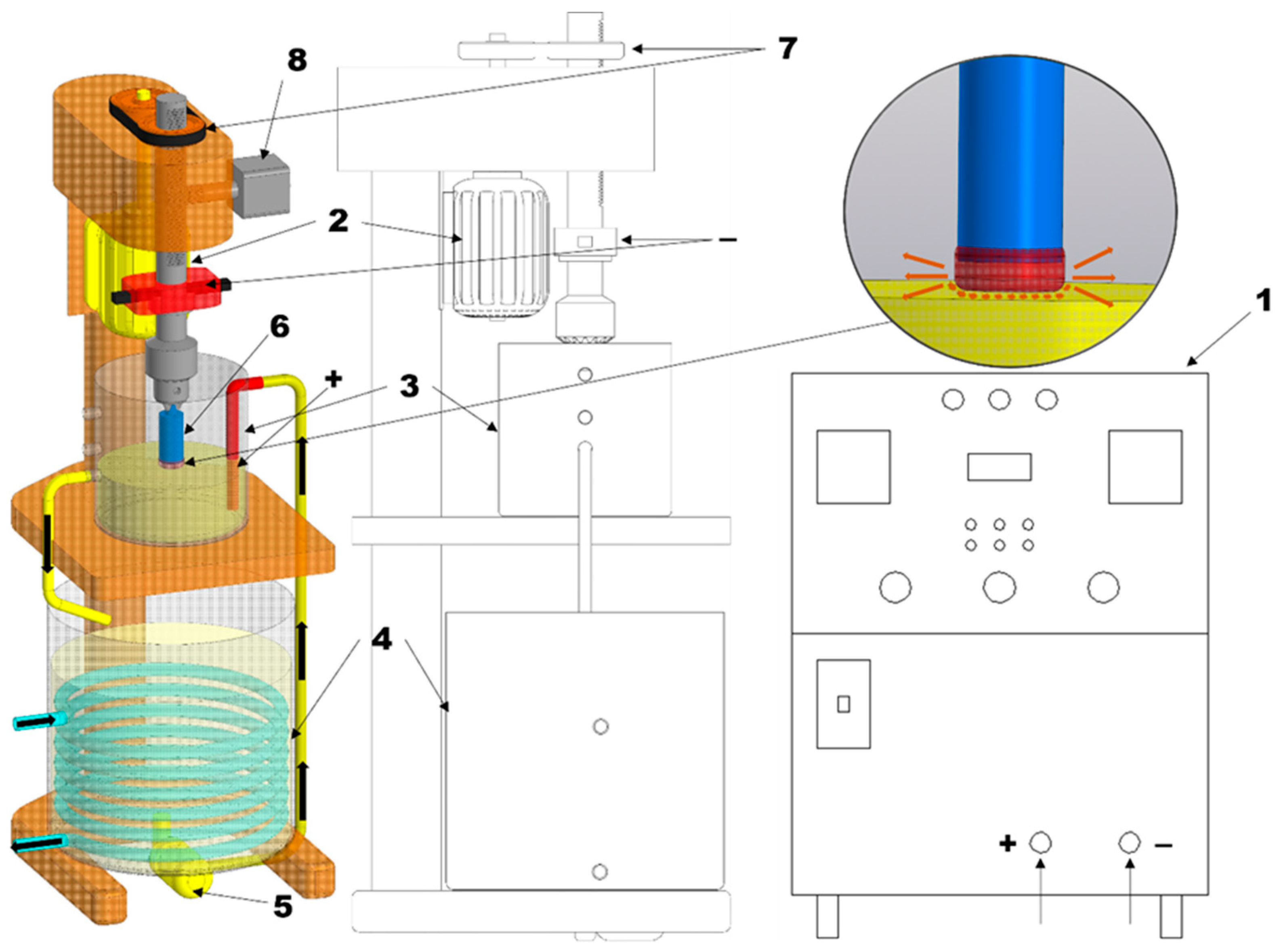
3) and 90% distilled water. The second electrolyte consisted of 10% sodium chloride (NaCl) and 90% distilled water. For the experiment, a setup was constructed based on a drilling unit according to the scheme shown in
Figure 1, with a 63 kW DC rectifier used as the power supply.
The process of obtaining iron-based powder was carried out according to the following scheme: First, the electrolyte was poured into the working bath (4). Using the pump (5) located at the bottom of the bath, the electrolyte was circulated through pipelines into the processing chamber (3). The electrolyte was discharged back into the working bath through specially designed drain holes, ensuring continuous circulation of the liquid. The electrolyte flow rate was maintained within 4–7 L/min, while cooling water passing through the heat exchanger circulated at 3–6 L/min, which made it possible to keep the electrolyte temperature at 50–60 °C. The workpieces (6) were fixed in a holder and placed in the electrolyte in such a way that the processing zone was located at a distance of 2–3 mm from the electrolyte surface. The anode, immersed in the electrolyte working bath, was connected to the positive pole of the power supply (1), while the sample, serving as the cathode, was connected to the negative pole. Then voltage was applied to the electrodes, and the workpiece was moved downward at a speed of 2.5 mm/min using the vertical feed mechanism (8). As a result of the switching of electric current through the electrolyte from the anode to the cathode—the workpiece—a plasma layer was formed on its end surface. This layer was heated by micro-electric discharges. The electric discharges transferred energy through the plasma layer and caused melting and activation of a thin molten layer on the end face of the workpiece [
43].
X-ray phase analysis was carried out using an X’Pert PRO PANalytical diffractometer (PANalytical BV, Almelo, The Netherlands) equipped with a copper anode tube operating at 40 kV and 30 mA. Recording of Cu-Kα radiation (λ = 1.541 Å) was performed in the 2θ range from 30° to 90°, with a scanning step of 0.02° and a counting time of 0.5 s per step [
44]. Processing and interpretation of the obtained diffraction patterns were carried out using the HighScore Plus software package version 3.0.5. The sizes and elemental composition of the metallic powders were examined using scanning electron microscopy (SEM) with an SEM3200 instrument (CIQTEK Co., Ltd., Hefei, China). After the experiment, the obtained powder was sieved to below 100 microns using an AS 200 sieving machine (Retsch, Hann, Germany). Using the Fiji software, version 2.17.0, we carried out particle morphology analysis: the scale was set using a ruler, the powder particles were segmented by threshold processing and the ‘Analyze Particles’ command, where their geometric parameters (area, perimeter, Feret’s diameter, circularity) were obtained. The results were saved in a CSV file, and then in Python version 3.13.7 a classification was performed according to the degree of circularity (perfectly spherical, 0.8–1.0; moderately spherical, 0.6–0.8; and irregularly shaped, below 0.6), and illustrative diagrams were plotted. The measurement of powder sizes up to 100 microns was carried out using a Winner2005A laser particle size analyzer (Jinan, Shandong Province, China). Distilled water was used as the dispersant, the sample concentration was 12.84444, the analysis mode was lognormal distribution, and the measurement range was 0.01–1000 μm.
3. Results and Discussion
To determine the optimal processing regime, powder was produced at rotation speeds of 1000, 1500, 2000, and 2500 rpm in a single-stage mode at a voltage of 350 V in a 10% sodium chloride (NaCl) electrolyte. As shown in
Figure 2a–d, the higher the rotation speed of the workpiece was, the smaller the powder particle diameter obtained was. However, during single-stage processing the workpieces overheated; therefore, further experiments were carried out in a two-stage mode (
Figure 2e–f): initially, a voltage of 350 V was applied to the electrodes for 5 s to ignite the plasma, followed by 250 V to sustain the plasma until the end of the process at a rotation speed of 2500 rpm.
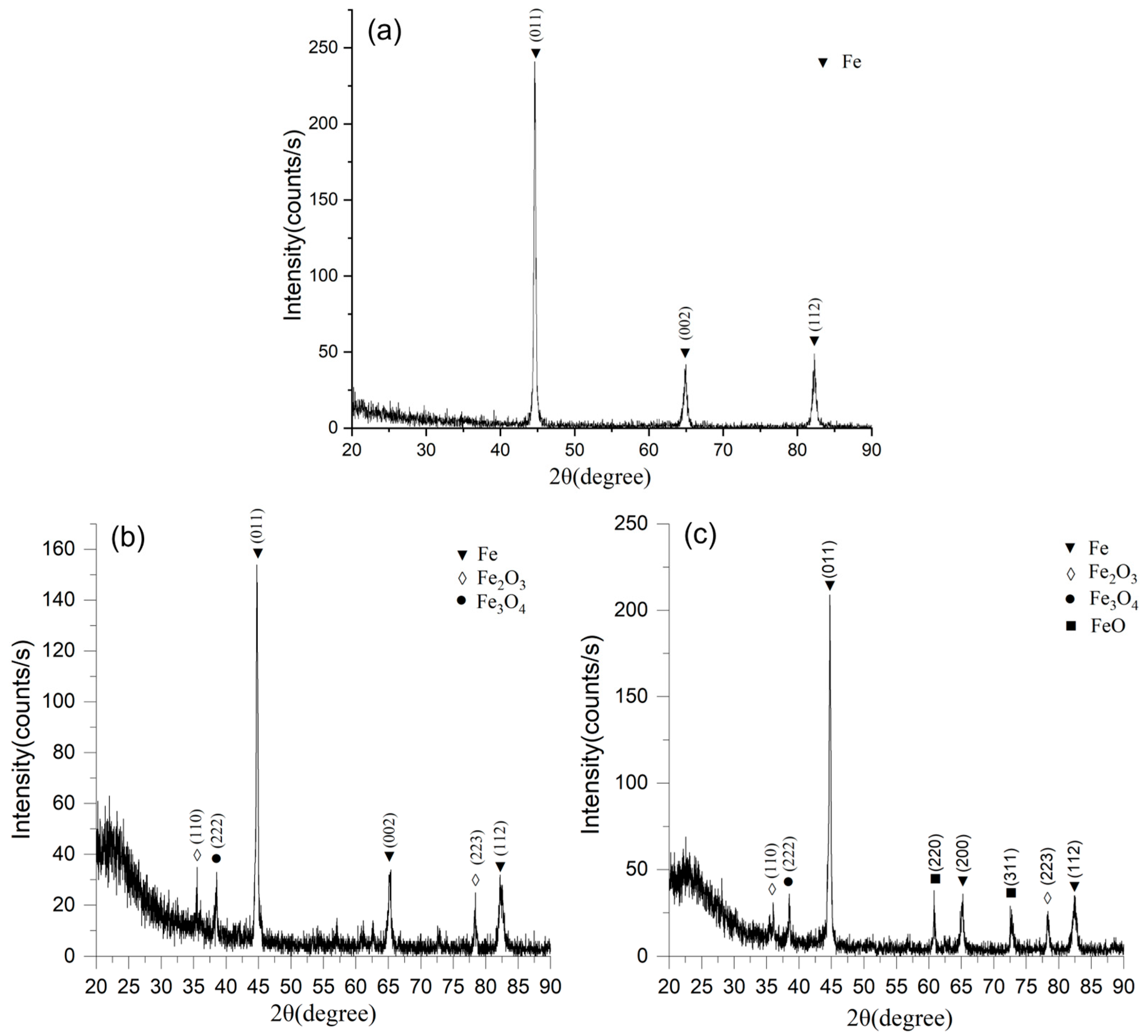
Figure 3a shows the X-ray diffraction pattern of the initial sample. The main diffraction peaks correspond to α-Fe with a cubic body-centered (BCC) crystal lattice. The most intense reflection is recorded from the (110) plane at 2θ ≈ 44.7°, which is a characteristic diffraction maximum of iron in the BCC modification. Additionally, less pronounced peaks are recorded from the (200) and (211) planes, which also confirm the presence of the metallic iron phase.
Figure 3b shows the X-ray diffraction pattern of the powder synthesized in a 10% NaCl solution. As in the initial state, the main phase remains α-Fe, which is confirmed by the presence of intense reflections from the (110), (200), and (211) planes. However, unlike that of the initial powder, the spectrum is characterized by the appearance of additional diffraction maxima belonging to iron oxide phases: hematite (Fe
2O
3) and magnetite (Fe
3O
4). The presence of these compounds indicates partial oxidation of the particle surfaces during the electroplasma synthesis in the chloride-containing medium. The formation of these oxides can be explained by the high reactivity of active chlorine ions, as well as by local overheating in the discharge zone, which promotes the intensification of oxidation processes. At the same time, the quantitative fraction of the metallic phase remains predominant, which confirms the stability of the iron matrix even under high discharge energy conditions.
Figure 3c shows the X-ray diffraction pattern of the powder obtained by electroplasma synthesis in a 10% Na
2CO
3 solution. In this case, along with the reflections of α-Fe, the spectrum clearly shows peaks of oxide phases of various types: Fe
2O
3, Fe
3O
4, and FeO (wüstite). The appearance of the FeO phase is particularly noteworthy, since this iron oxide is thermodynamically unstable under normal conditions. Its presence indicates the occurrence of high-temperature reduction processes followed by rapid cooling of the particles in the carbonate electrolyte, which stabilizes this modification. Carbonate ions, unlike chloride ions, create less aggressive oxidation conditions, which promotes the formation of a more diverse set of oxide phases. Comparative analysis of the X-ray diffraction data (
Figure 3a–c) allows us to conclude that in all cases the main crystallographic phase remained metallic iron with a BCC structure, which exhibits high stability under electroplasma synthesis conditions. At the same time, the nature of the electrolyte has a significant effect on the formation of oxide compounds. For NaCl, the formation of hematite and magnetite is characteristic, whereas the use of Na
2CO
3 leads to additional stabilization of the FeO phase. The obtained results indicate that the chemical composition of the electrolyte is a determining factor in the phase formation mechanism and can be purposefully used to control the structural–phase state of the synthesized powders.
The powder obtained at 350 V in a 10% NaCl solution under the single-stage mode (
Figure 4) was characterized by mixed morphology: along with predominantly spherical particles sized 40–95 μm, angular and fragmented formations were also present, reflecting a combination of melting with subsequent quenching and mechanical dispersion processes. X-ray diffraction analysis revealed the dominance of α-Fe with a BCC crystal lattice, as well as the presence of the oxide phases Fe
2O
3 and Fe
3O
4, formed during rapid cooling of the melt and its interaction with the electrolyte. EDS analysis data, as shown in
Figure 4b, confirm the predominance of iron (about 80 wt.%) and a significant oxygen content (≈19 wt.%), indicating pronounced surface oxidation, which is fully consistent with the XRD results. In addition, Mn (≈2.4 wt.%) and Si (≈1 wt.%) were detected in the composition, which could not be identified by X-ray diffraction due to their low concentration but were localized on the particle surfaces and may have acted as microalloying impurities.
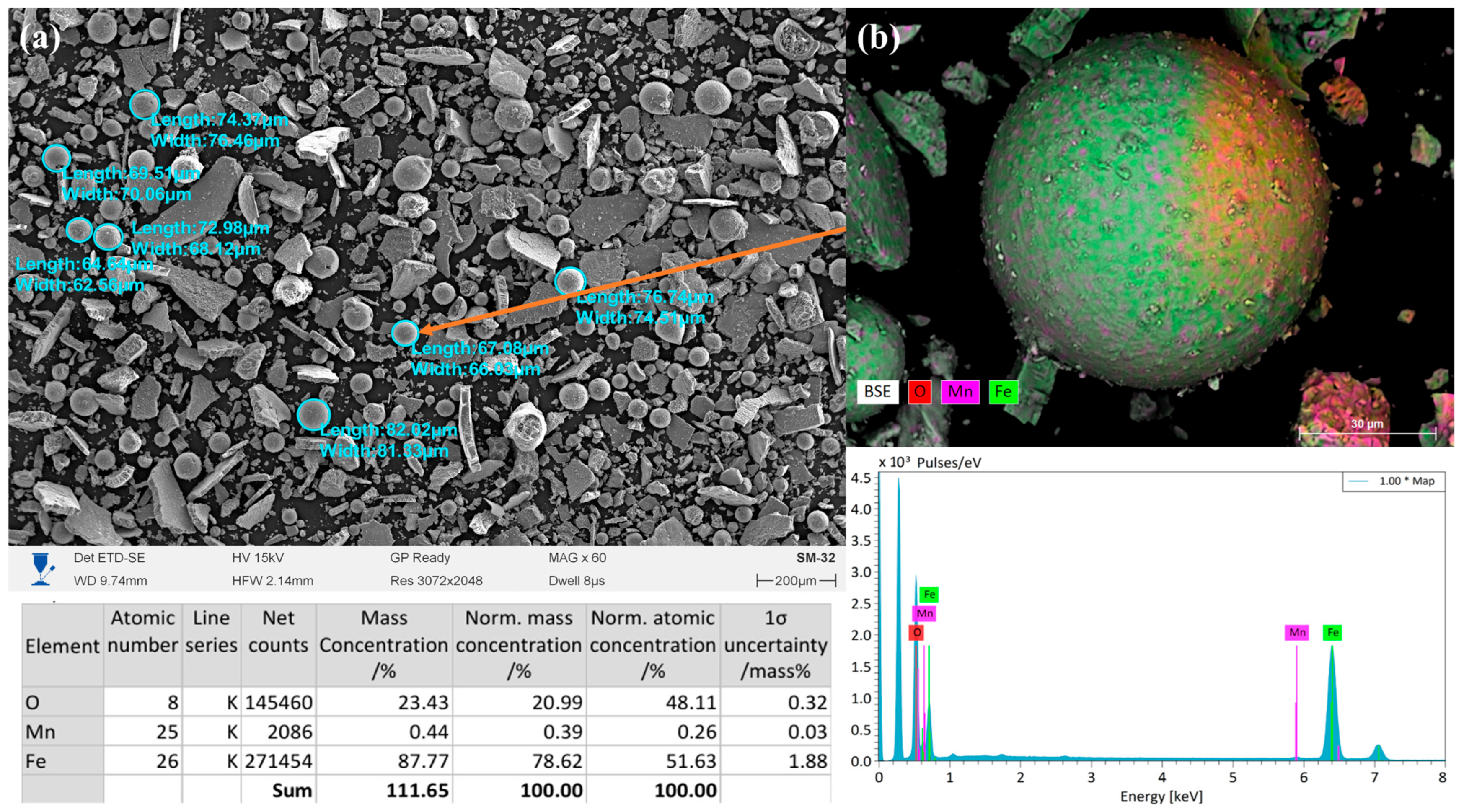
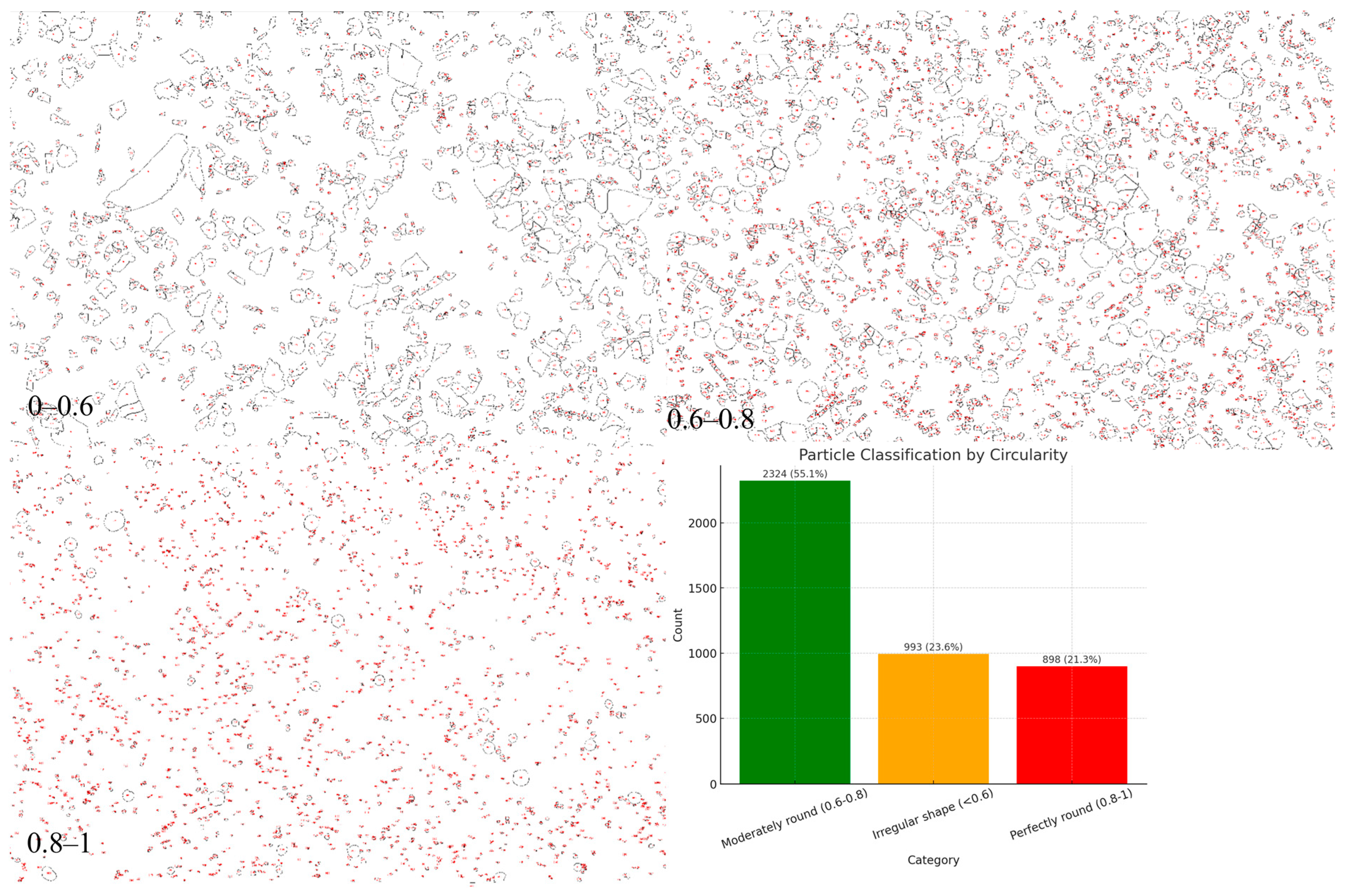
The powder obtained in the two-stage mode (5 s at 350 V followed by 250 V until the end of the process) in a 10% NaCl solution, as shown in
Figure 5, was characterized by a more homogeneous morphology compared to that from the single-stage mode. SEM images show that spherical and rounded particles with diameters of 60–80 μm predominated, along with some angular fragments. The size of the spheres ranged from 62 to 82 μm, which was slightly smaller than that in the single-stage mode at 350 V. This is attributed to the milder dispersion conditions and process stabilization achieved by lowering the voltage. EDS analysis showed that the powder consisted predominantly of iron (87.77 wt.%), with a significant oxygen content (23.43 wt.%), indicating the formation of oxide layers on the particle surfaces. The manganese content was minimal (0.39 wt.%), which may have been associated with its local segregation or presence in the form of fine oxide inclusions. Compared to that in the powder obtained at a constant 350 V, a higher oxygen content is observed, indicating more pronounced surface oxidation. Surface mapping (EDS mapping) confirmed a uniform distribution of Fe throughout the particle volume, while oxygen was concentrated mainly on the surfaces of the spheres, forming oxide shells. Mn was detected in the form of point inclusions, which is consistent with its low concentration. Thus, the powder synthesized in the two-stage mode exhibited a predominantly spherical morphology with an oxide shell and a high Fe content. The combination of short-term high energy (350 V) followed by a milder regime (250 V) promoted the formation of more homogeneous spherical particles but enhanced surface oxidation processes. This may have affected the performance properties of the material—enhancing its stability and adhesion characteristics while reducing the purity of the metallic phase.
The powder obtained in the two-stage mode (5 s at 350 V followed by 250 V) in a 10% Na
2CO
3 electrolyte was characterized by a more pronounced spherical morphology and smaller particle sizes compared to the NaCl electrolyte (
Figure 6). SEM images reveal a large number of smooth spherical particles with diameters of 20–75 μm, along with angular fragments. Such a morphological outcome is attributed to the combination of the initial high-energy discharge, which enables melting and sphere formation, and the subsequent milder regime, which promotes stabilization and quenching of the particles in the molten state. According to EDS analysis, the powder consisted mainly of iron (72.24 wt.%), oxygen (24.54 wt.%), and a noticeable amount of sodium (6.94 wt.%), as well as Si (0.82 wt.%) and Mn (1.32 wt.%). The presence of Na is associated with the use of the carbonate electrolyte and indicates partial incorporation of sodium ions into the surface layers of the particles. The high oxygen concentration indicates intensive surface oxidation and the formation of iron oxide phases (FeO, Fe
3O
4, Fe
2O
3), as well as the possible involvement of sodium in the formation of complex oxide shells (Na–Fe–O). Elemental mapping showed a uniform distribution of Fe throughout the volume of the spherical particles, while oxygen and sodium were mainly concentrated on the surface, confirming the formation of oxide shells with Na inclusions. Si and Mn exhibited a point-like distribution, typical of surface impurities and microalloying additions. The powder synthesized in the two-stage mode using the Na
2CO
3 electrolyte was distinguished by a more uniform spherical morphology and higher oxygen and sodium contents compared to its counterpart obtained in NaCl. This indicates that the carbonate medium promotes more intensive oxidation and the formation of mixed oxide shells, which may affect the physico-chemical and performance characteristics of the obtained material.
Comparative analysis of the morphology and chemical composition of powders obtained under different regimes and in various electrolytes demonstrates the significant influence of the medium’s nature on the dispersion processes and the formation of particle structures. In the case of the two-stage mode (350 V–5 s, followed by 250 V) in the Na
2CO
3 electrolyte, the highest fraction of spherical particles with diameters of 20–75 μm, smooth surfaces, and homogeneous morphology was observed, as shown in
Figure 6a. EDS analysis revealed, in addition to iron (≈72 wt.%) and oxygen (≈24.5 wt.%), a significant sodium content (≈7 wt.%), which is explained by the involvement of Na
+ ions from the carbonate electrolyte in the high-temperature interactions at the metal–electrolyte interface. During electroplasma discharges, part of the Na
+ ions was adsorbed and incorporated into the surface oxide layers, forming complex Na–Fe–O compounds, which resulted in their retention within the particle composition. In the two-stage mode with NaCl, predominantly spherical particles (60–80 μm) were also formed; however, their quantity was lower and the surface was more heterogeneous. According to EDS data, Fe (≈88 wt.%) and O (≈23 wt.%) were detected, while sodium was not observed due to the low solubility of Na
+ ions from NaCl in the formed oxide phases. For the single-stage mode at 350 V in NaCl, the morphology was characterized by a predominance of angular and fragmented particles, whereas spherical forms were less common (40–95 μm), which is associated with intensive fragmentation under the high-energy discharge. Thus, the use of Na
2CO
3 promoted the stabilization of the sphere formation process and led to the incorporation of sodium into the surface layers of the particles, whereas under NaCl conditions the formation of spheres was limited and sodium impurities in the composition were not detected.
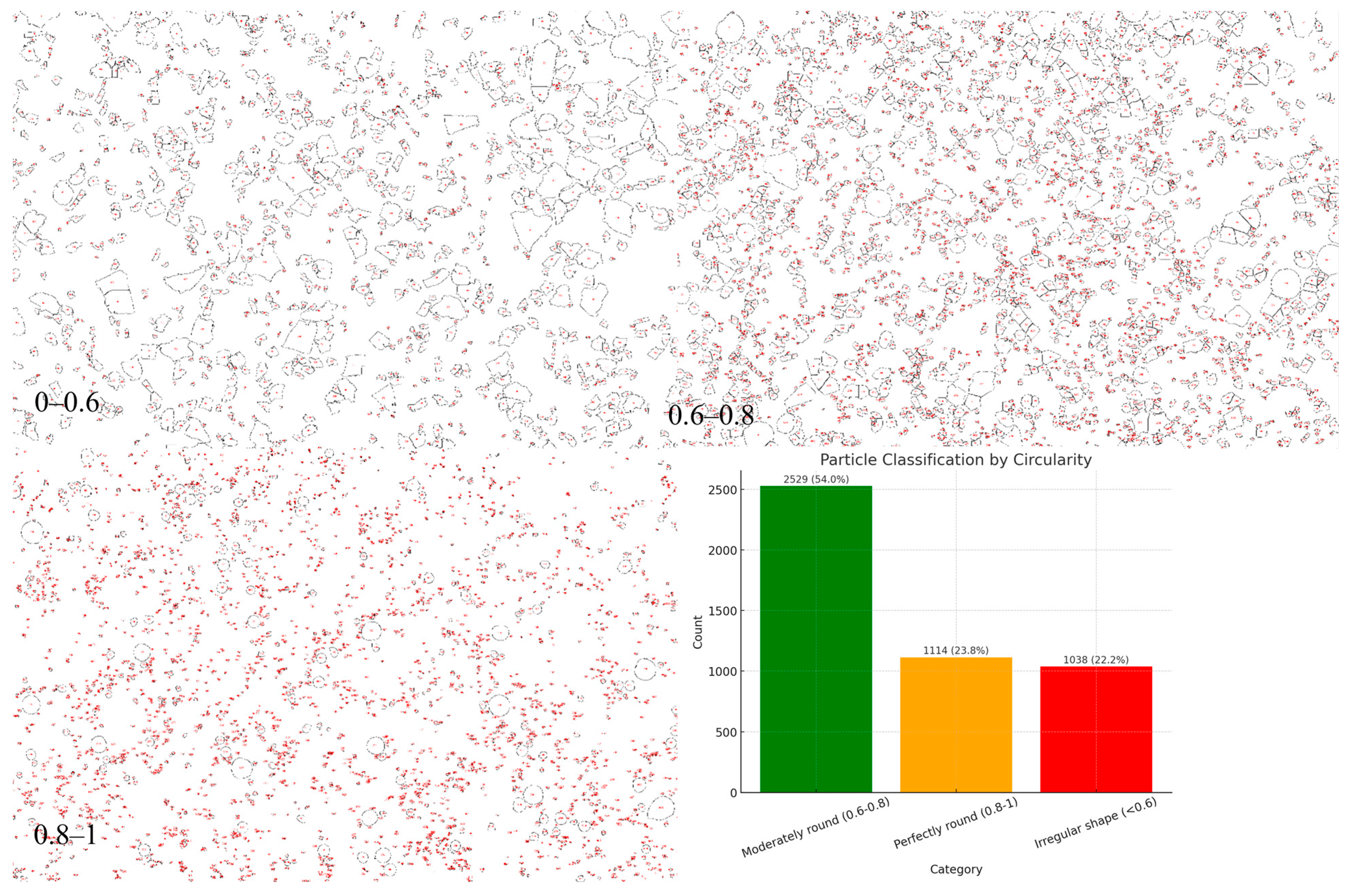
Morphological analysis of powders synthesized by the electroplasma method in a 10% NaCl solution in a single-stage mode showed, as seen in
Figure 7, the predominance of particles with a moderate degree of circularity. According to the classification results based on the circularity parameter, the largest portion of the powder (54.0%, 2529 objects) belonged to the category of moderately rounded particles (0.6–0.8). The fraction of particles with a high degree of sphericity (perfectly rounded, 0.8–1) was 23.8% (1114 objects), which indicates the formation of a fairly significant fraction of spherical granules. At the same time, about 22.2% (1038 objects) had an irregular shape (circularity < 0.6), which indicates the presence of deformed and fragmented structures formed under conditions of unstable cooling and non-uniform exposure to plasma–electrolytic discharges. In the one-stage mode of electro-plasma synthesis in a NaCl medium, a powder was formed in which moderately rounded particles predominated, with a relatively uniform distribution between the fractions of perfectly spherical and irregularly shaped particles. These results indicate that the one-stage mode provides satisfactory morphology characteristics; however, it requires further optimization to increase the proportion of perfectly spherical granules and reduce the number of defect-shaped particles.
Morphological analysis of the powders obtained by the electro-plasma method in a 10% NaCl solution in the two-stage mode (
Figure 8) showed that the particles were characterized by a diversity of shapes, which was confirmed by the classification according to the circularity parameter. According to the distribution, the largest proportion of particles (55.1%, 2324 objects) belonged to the category of moderately rounded (0.6–0.8). A significant portion of the particles (23.6%, 993 objects) had an irregular shape (circularity < 0.6), which indicates the presence of fragmented and deformed structures formed under unstable cooling conditions and the intense influence of electro-plasma discharges. The proportion of particles with a high degree of sphericity (perfectly rounded, 0.8–1) amounted to only 21.3% (898 objects), which was noticeably lower than for powders obtained in the Na
2CO
3 medium. The obtained data indicate that the use of a chloride-containing electrolyte (NaCl) leads to the formation of powders with a lower proportion of spherical particles and a higher fraction of irregularly shaped particles. This can be explained by the high aggressiveness of chloride ions, which enhance oxidation and destabilization processes of droplets in the discharge zone, thereby reducing the likelihood of forming perfectly spherical granules. Overall, the NaCl medium forms powders with satisfactory but less optimal morphological characteristics compared to Na
2CO
3, which indicates the importance of selecting the electrolyte composition to control the geometry and technological suitability of the synthesized powders.
The results of the morphological analysis of powders obtained by the electro-plasma method in a 10% Na
2CO
3 solution (
Figure 9) showed heterogeneity in particle shape, which was confirmed by the classification according to the circularity parameter. According to the obtained data, the largest portion of the powder (about 49.6%, or 2518 particles) belonged to the category of moderately rounded (circularity = 0.6–0.8). The proportion of particles with a high degree of sphericity (perfectly rounded, circularity = 0.8–1) amounted to 28.4% (1441 particles), which indicates the presence of a significant fraction of powder with favorable morphology for thermal spraying processes and additive technologies. At the same time, about 22.0% (1118 particles) were characterized by an irregular shape (circularity < 0.6), which may be associated with uneven cooling of molten droplets in the plasma–electrolytic discharge zone, as well as with particle fragmentation during rapid quenching. Morphological analysis revealed that more than 70% of the particles had a rounded or nearly spherical shape, which confirms the effectiveness of the electro-plasma method for obtaining powders with optimal geometry. However, the presence of a significant fraction of irregularly shaped particles indicates the need to optimize the synthesis parameters (voltage, current density, pulse duration, electrolyte composition) in order to increase the degree of sphericity of the powder and improve its technological characteristics.
The results of particle size distribution measurements, shown in
Figure 10, indicate that the particles had a relatively narrow size range with a median diameter (D50) of 54.8 μm. According to the data, 10% of the particles (D10) were smaller than 37.0 μm, and 90% of the particles (D90) were smaller than 81.1 μm, indicating a uniform distribution without a pronounced fraction of ultrafine or coarsened agglomerates. The obtained surface-to-volume ratio (S/V) was 1148.6 cm
2/cm
3, which confirms the high specific surface area of the powder and its potentially enhanced reactivity in subsequent technological processes (e.g., sintering or heat treatment). The histogram shows that the particle size distribution follows a Gaussian pattern with a maximum in the range of 50–60 μm, which is consistent with the median value. Thus, the powder is characterized by good particle size uniformity, predominance of medium dispersity, and a sufficiently high specific surface area, making it promising for applications in powder metallurgy and coatings where a combination of high reactivity and uniform structure is required.
