1. Introduction
Nickel-based superalloys are developed for use in harsh environments such as high temperatures and oxidation atmospheres. They are significantly resistant to creep, fatigue, and oxidation and can be used at temperatures above 700 °C. Various elements are alloyed for solution strengthening (matrix (γ), e.g., Cr, Co, W, and Mo), precipitation hardening (γ’ (Ni
3Al), e.g., Al, Ti, and Nb), and GB strengthening (e.g., C, B, and Zr). Creep behavior is dominant at high temperatures due to GB sliding. Numerous researchers have been studying the increase in creep resistance via GBs strengthening. Most cast and wrought nickel-based superalloys are added to C for the precipitation of carbides at GBs. Carbides are classified as MC, M
6C, M
7C
3, and M
23C
6, where M stands for a metal atom such as Cr, Mo, Ti, Nb, Zr, Ta, V, and Hf. In many nickel-based superalloys, the MC carbide, usually Ti, Nb, Zr, Ta, and Hf, since these are strong carbide formers, crystallizes from the liquid phase. The Cr
23C
6 carbide forms at low temperatures and is usually found to precipitate at matrix (γ) GBs. Several carbide morphologies, for example, globular, blocky, and script, have been reported [
1]. With the addition of B, borides are also formed at GBs and are reported to be beneficial in hindering GB sliding. C and B, which add a trace amount and strengthen GBs in nickel-based superalloys, are discussed, along with Zr [
2].
B and Zr are reported to increase creep resistance. Decker et al. hypothesized that trace elements hindered the agglomeration of M
23C
6 and prevented the depletion of γ’ phases at GBs [
3]. Usually, when M
23C
6 carbides are agglomerated and formed nearly continuously at GBs, the creep-resistant properties decrease due to embrittlement. B has a low solubility of the matrix in nickel-based superalloys. It is well known that B is segregated into GBs and forms borides [
4,
5,
6,
7,
8]. Numerous researchers have reported that boride precipitation, such as M
2B, M
3B
2, and M
5B
3, was observed by adding B in nickel-based superalloys [
9,
10,
11,
12,
13,
14]. Several studies have also reported that Cr
23C
6 carbides are detected in a significant amount of B with C [
15,
16,
17]. Zr has 2.74 wt.% solubility in nickel at 1170 °C, is entirely soluble in Ti and Nb, and can form MC carbides. Murata and Yukawa reported that ZrC precipitates were formed during heat treatment upon the addition of Zr in the IN 100 alloy [
18] and Tsai et al. observed the refinement of grains and carbides [
19]. Kontis et al. proposed that Zr could stabilize MC carbides during both heat treatment and the creep test [
20]. However, Theska et al. hypothesized that Zr did not form primary MC carbides but promoted the formation of γ’ phases. Numerous researchers have endeavored to explain the effect of B and Zr on GBs. Nevertheless, research is still progressing to understand the mechanism of trace elements [
21,
22,
23,
24,
25,
26]. The effect of trace elements on creep resistance was discovered in the 1950s. However, the alteration of microstructure by the addition of B and Zr has not been clearly understood until now.
Our previous study also attempted to discuss the effect of B and Zr. Trace amounts of B and Zr were added to a designed nickel-based superalloy, and the microstructure and creep-resistant properties were evaluated [
27]. However, the effect of B and Zr had been partially investigated. By adding B and Zr, numerous nanometer-sized (Nb, Ti)C and Cr
23(C, B)
6 were observed at GBs, but the forming process could not be confirmed. Especially in the case of Zr, it was assumed, through the literature investigation, that this was because Zr was not detected.
Although numerous researchers, including our previous research, have been focused on the effect of B and Zr, the following questions have not been clearly solved:
What is the alteration in microstructures observed upon the addition of B and Zr?
Why does creep resistance significantly increase in the case of the addition of B?
Why does the addition of B and Zr increase the creep resistance of nickel-based superalloys more than just the addition of B?
Why do nanometer-sized (Nb, Ti)C and Cr23(C, B)6 form upon the addition of B and Zr?
To answer these questions, this study investigated the effects of B and Zr separately in the designed nickel-based superalloy. This alloy was formulated to prevent the formation of the TCP phase, eventually improving creep resistance and promoting the precipitation of the γ’ phase. The key elements for controlling these phases were identified through thermodynamic calculations to search for stable phases with consideration for the required mechanical properties. These calculations were performed under various alloy conditions using JMatPro software (Sente Software Ltd., Surrey, UK) version 5.1 with the Ni database. Our previous paper described the detailed design process [
28]. The design stage of this alloy is listed briefly in
Table 1. The reference alloy consists of topologically close-packed (TCP) phases such as sigma (σ), eta (η), and G phases, which are formed at GBs and deteriorate the mechanical properties. The concentration of alloying elements was adjusted to control the formation of the TCP phases. The W added alloy is designed to improve the creep strength, due to a decreased concentration of Cr and Mo. The alloy in the last stage, which controls the formation of σ, η, and G phases and adds W, is named a phase-controlled nickel-based superalloy. The chemical composition of this alloy is (in mass%) 22Cr, 20Co, 2W, 2Nb, 1.5Al, 1.5Ti, 0.03C, and Ni balance.
The phase-controlled nickel-based superalloy, expressed as the basis alloy, is cast without B and Zr. An alloy containing 90 ppm of Zr is designated as the 90Zr alloy, while the 80B alloy contains an addition of 80 ppm B. The 80B-80Zr alloy is cast with additions of 80 ppm B and 80 ppm Zr. Each alloy is progressed with identical heat treatment and forging, and the alteration of microstructure is investigated. The effect of B and Zr is discussed by comparing four alloys.
2. Materials and Methods
Four phase-controlled nickel-based superalloys with trace elements (i.e., basis, 90Zr, 80B, and 80B-80Zr, ppm) were cast using vacuum induction melting and centrifugal casting (Supercast-titan, Linn High Temp GmbH, Eschenfelden, Germany). Raw materials (e.g., Ni, Co, W, Nb, Ti, and Al) and master alloys (e.g., Ni-51Cr, Ni-B, Ni-Zr, and Ni-C) were weighed to ~800 g and placed in a preheated Al2O3 crucible. The reason why certain materials are used in the master alloy is to cast an alloy of a sure composition. The casting chamber, including the crucible and mold, maintained vacuum conditions during the melting and casting process. When the vacuum level reached 0.01 hPa, a voltage was supplied at 120 V and was then increased from 120 V to 320 V until melt was observed through the inspection window. While raw materials and master alloys were fully melted, the melt temperature was measured using a pyrometer (RAYMR1SBSF, Raytek Corp., Santa Cruz, USA). The melt was held for 2 min to dissolve all elements and, at that time, the melt temperature had been increased from 1600 °C to 1700 °C, and then the casting chamber was spun at 200 rpm for 2 min. The melt, which had superheating and centrifugal force for fluidity, was poured into a preheated Al2O3 mold for sound casting. Four ingots were homogenized in the furnace at 1200 °C for 16 h, followed by air cooling to room temperature and forging at 1100 °C, with a final forging reduction of 40%. Solution treatment was performed at 1200 °C for 30 min to dissolve precipitates and allow for recrystallization, followed by water quenching. The final aging step was performed at 800 °C for 16 h to allow the precipitation of γ’ phases and carbides. After processing, the compositions of the four ingots were analyzed for major alloying elements, using energy dispersive spectroscopy (EDS, X-Max, Oxford Instruments, High Wycombe, UK); trace elements such as B and Zr, using a spark emission spectrometer (QSN 750, OBLF GmbH, Witten, Germany); and carbon, using a carbon sulfur analyzer (CS-800, ELTRA GmbH, Haan, Germany).
Creep testing was performed at 700 °C using a small punch creep testing machine. Four casting ingots were cut in specimens for the small punch creep test with a wire-cutting machine and were ground to a 2000–grid abrasive SiC paper on both sides to avoid the influence of heat buildup during the cutting stage. After the grinding step, the dimensions of the specimens were 10 × 10 × 0.5 mm and the deviation of thickness was controlled by
10 μm. The specimen was placed between the upper and lower die and then a ceramic ball (Si3N4, ϕ 2.4 mm) and puncher were inserted through the upper die without loading. The assembly, including the upper and lower die, the ceramic ball, the puncher, and the specimen, was placed in a furnace of the small punch creep testing machine. The atmosphere in the furnace was deflated to −1013.25 hPa using a rotary vacuum pump and then high-purity argon was pressurized to 60 hPa to prevent oxidation. The temperature was increased to 700 °C for 2 h and was maintained at 700 °C for 1 h to obtain uniform heat distribution in the assembly. After that, a constant load of 491 N (50 kgf) was applied to the specimen by the ceramic ball and the puncher. A linear variable displacement transducer measured displacements with a resolution of 1 μm and tests were terminated when displacements were observed to increase significantly.
Also, the four casting ingots were worked into samples for metallographic observation. For microstructure observation on GBs, samples were polished to a 1 μm finish and electrical etching was performed using a mixed etchant of perchloric acid, propionic acid, and ethanol (1:3:4). Samples were analyzed to identify carbides and precipitates on GBs using a field emission gun scanning electron microscope (SEM, JSM-7600F, JEOL Ltd., Akishima, Japan), combined with EDS. The precipitate at the GBs in samples containing B (i.e., 80B and 80B-80Zr) was observed using transmission electron microscopy (TEM, JEM-ARM200F, JEOL Ltd., Akishima, Japan), combined with EDS and electron energy loss spectroscopy (EELS). These samples were prepared using a jet polisher (TenuPol-3, Struers A/S, Ballerup, Denmark) with the mixed etchant. The TEM was operated at an acceleration voltage of 200 kV and EELS maps were generated by integrating EELS signals of C (282.1~295.2 eV) and B (184.8~200 eV). To confirm the atom distribution of the precipitate at the GBs, samples containing B (i.e., 80B and 80B-80Zr) were worked into a nanotip shape using a dual-beam focused ion beam (FIB, Helios Nanolab 600, FEI, Hillsboro, OR, USA) microscope lift-out technique. Each nanotip was analyzed for the distribution of atoms on carbides and precipitates on GBs using an atom (APT, LEAP 4000X HR, CAMECA Inc., Madison, WI, USA) with laser pulse mode (UV, 355 nm wavelength) at a sample temperature of 53.9 K, 100 pJ pulse energy, 100 kHz pulse rate, and a detection rate of 0.5%.
Four samples were prepared for the basis and 80B-80Zr alloy to understand how precipitation progresses during heat treatment. As mentioned previously, the samples had been prepared using homogenized heat treatment and forging. Each sample was taken out from the furnace during solution and aging (0 h, 1 h, and 16 h) heat treatment. Samples were polished to a 1 μm finish and electrical etching was performed using a mixed etchant. Samples were analyzed to observe the precipitates on the GBs using SEM.
Finally, the stable phases and fractions, depending on the temperature in four phase-controlled nickel-based superalloys, were calculated using JMatPro to discuss the relation between the observed results and the trace amounts of B and Zr.
3. Results
The chemical compositions of the four alloys investigated in this study are listed in
Table 2. The 0.001 mass% B and 0.003 mass% Zr were detected in the basis alloy cast without trace elements. These detected levels, presented in the raw materials or introduced by contamination during the melting and casting process, were also considered the basis of chemical compositions. Throughout the analysis results listed in
Table 2, it is confirmed that the three alloys with B and Zr (i.e., 90Zr, 80B, and 80B-80Zr) were cast with the purpose composition.
Previous studies reported that B and Zr improve creep resistance in nickel-based superalloys and B is affected more significantly than Zr. Upon the inclusion of B and Zr, the creep resistance of the alloy is increased more so than the alloy with the addition of only B [
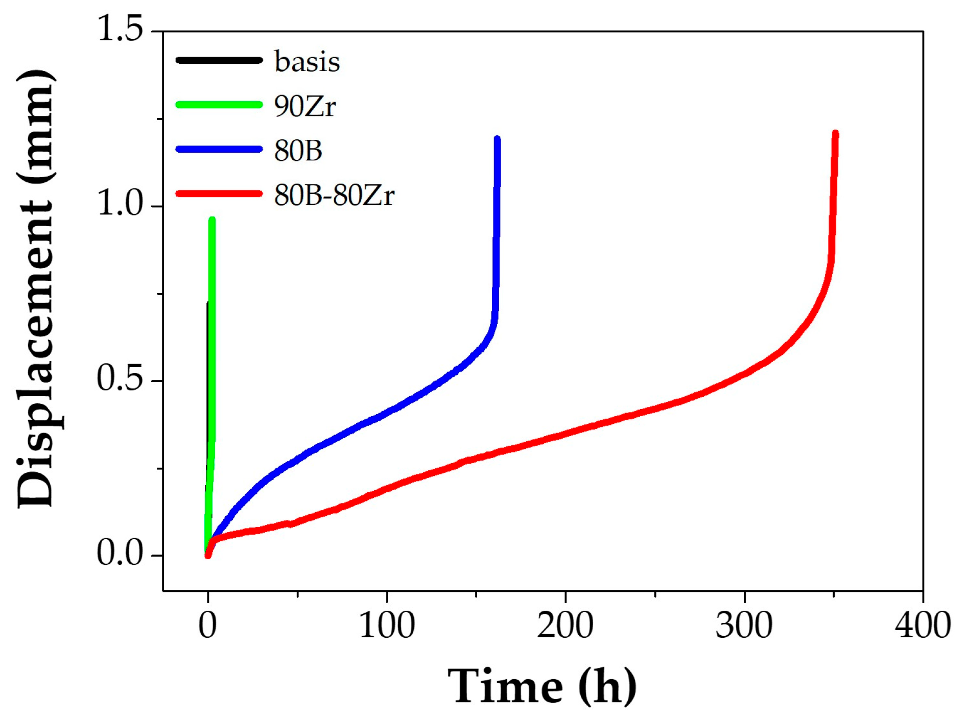
3]. The small punch creep test results used to compare creep resistance between previous studies and the cast alloys in this study are shown in
Figure 1. The rupture time and minimum displacement rate are listed in
Table 3. The rupture time of the 90Zr alloy was increased slightly than that of the basis alloy; the 80B alloy ruptured at 150 h and the rupture time of the 80B-80Zr alloy was measured as twice that of the 80B alloy. The minimum displacement rate of alloys containing added B is exponentially distinguished from the other alloys (basis and 90Zr). These results are similar to previous studies; however, it is still unclear how the trace elements have influenced the correlation between creep-resistant properties and microstructural alterations. Our previous study already reported the basis and 80B-80Zr [
27]; each effect of the trace elements has been focused on in this study.
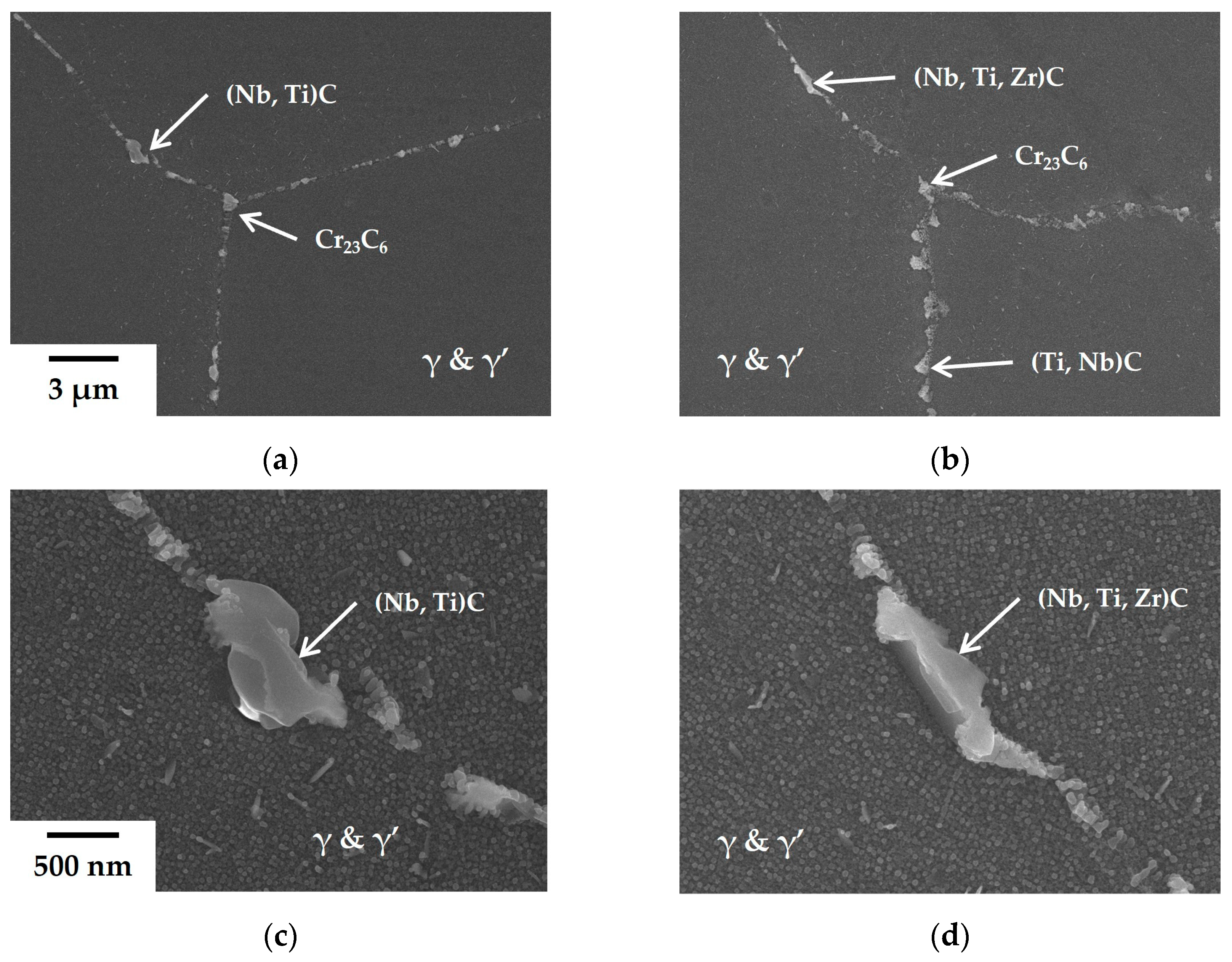
To understand the microstructural alteration of the trace elements, the microstructure was observed in the four phase-controlled nickel-based superalloys with trace elements. The added trace amount of B and Zr increased the creep resistance, but the microstructure observed was similar, including grain size, γ’ phase size, and distribution. However, the phases and morphologies of precipitates along the GBs are altered. The SEM images of the GBs of the basis and the 90Zr alloys are shown in
Figure 2. The GBs of the basis alloy consist of blocky (Nb, Ti)C and Cr
23C
6 carbides, which are micrometer-sized (
Figure 2a,c). Also, in
Figure 2c, the γ’ phases are observed in a rounded shape, about 30 nm in diameter. While the size and shape of carbides in the 90Zr alloy resemble those in the basis alloy, the proportion of MC carbides increases in
Figure 2b, and Zr is detected alongside Nb and Ti within certain MC carbides in
Figure 2d. These outcomes of Zr addition can be rationalized by the fact that Zr stabilizes (Nb, Ti)C carbides during heat treatment, aligning with previous studies and our hypothesis based on the literature review [
20,
27].
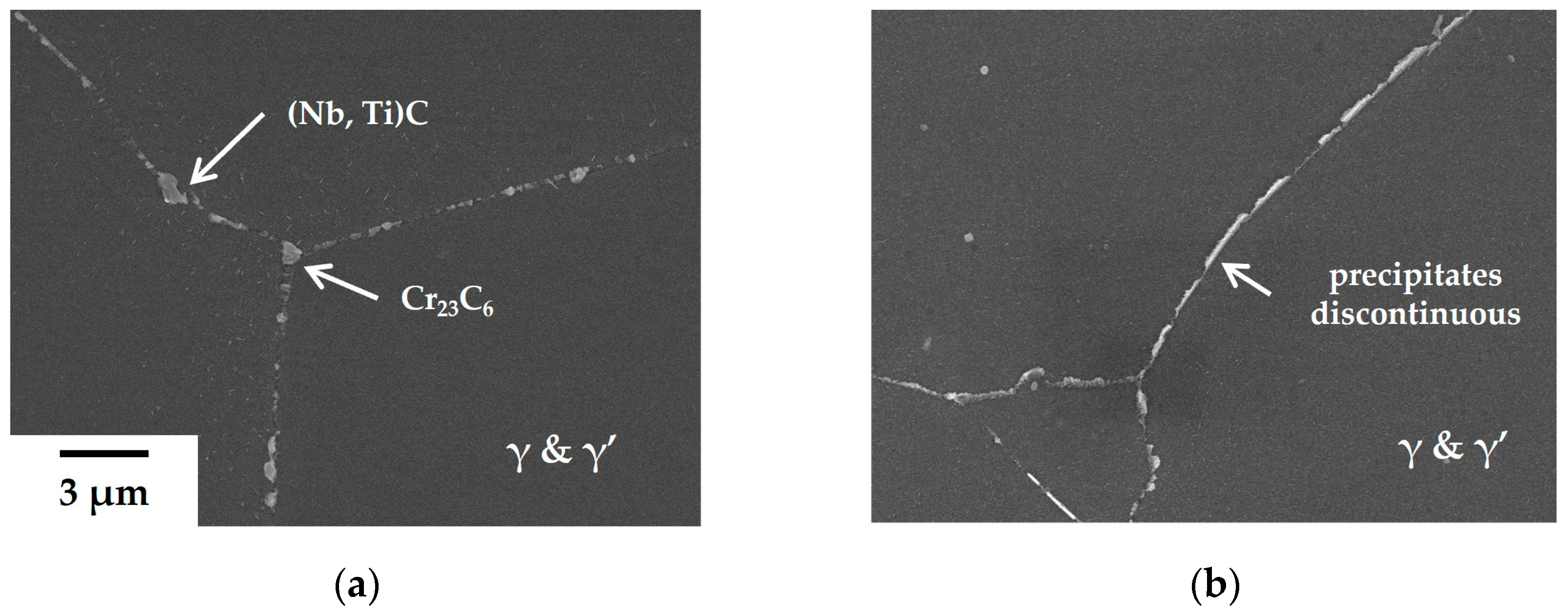
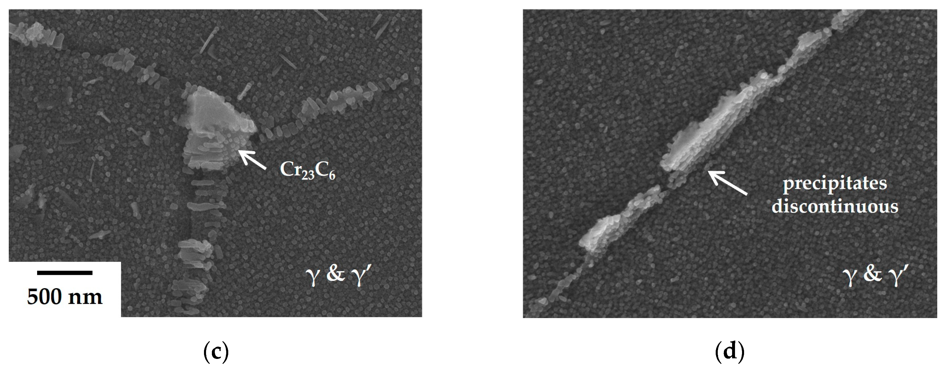
However, precipitates at the GBs of the 80B alloys undergo significant alteration (
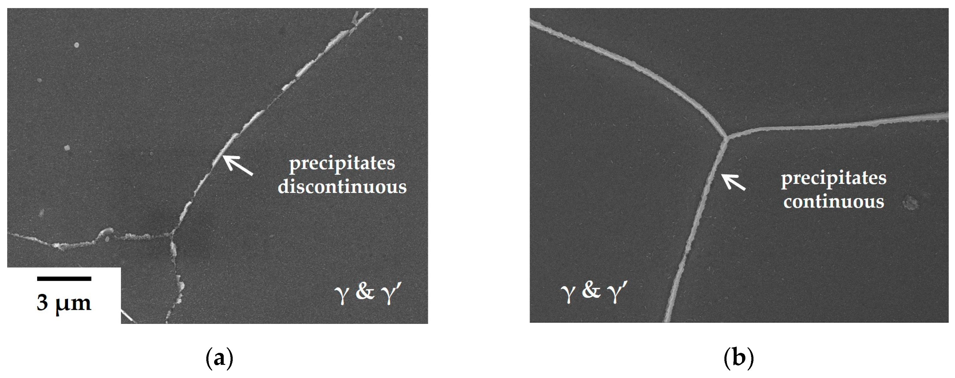
Figure 3). There are no blocky carbides present besides precipitates with a thickness of approximately 100 nm in
Figure 3b. In contrast, Cr
23C
6 carbide precipitates, about 500 nm in diameter, are typically formed at triple points on GBs in the base alloy (
Figure 3c), with the adjacent area of agglomerated Cr
23C
6 carbides exhibiting depleted γ’ phases. In the 80B alloy, the depleted area is not formed and the precipitates are surrounded by γ’ phases along the GBs, as depicted in
Figure 3d. These microstructural alterations significantly enhance the creep resistance of the 80B alloy compared to other alloys without B.
The formation of precipitates becomes more continuous with the addition of a trace amount of Zr to the 80B alloy, as illustrated in
Figure 4. This morphological change cannot be explained solely by the effect of Zr on stabilizing (Nb, Ti)C carbides during heat treatment. It may be necessary to reassess the influence of Zr. Based on the results of the creep tests and microstructural observations, it is hypothesized that these precipitates, formed upon the addition of B and Zr, significantly enhance creep resistance. It is well recognized that the creep-resistant properties can be improved if carbides and γ’ phases form a film structure along grain boundaries [
29]. Therefore, it is imperative to examine the internal structure of these precipitates. In order to elucidate the composition of precipitates, TEM and EDS analyses were conducted.
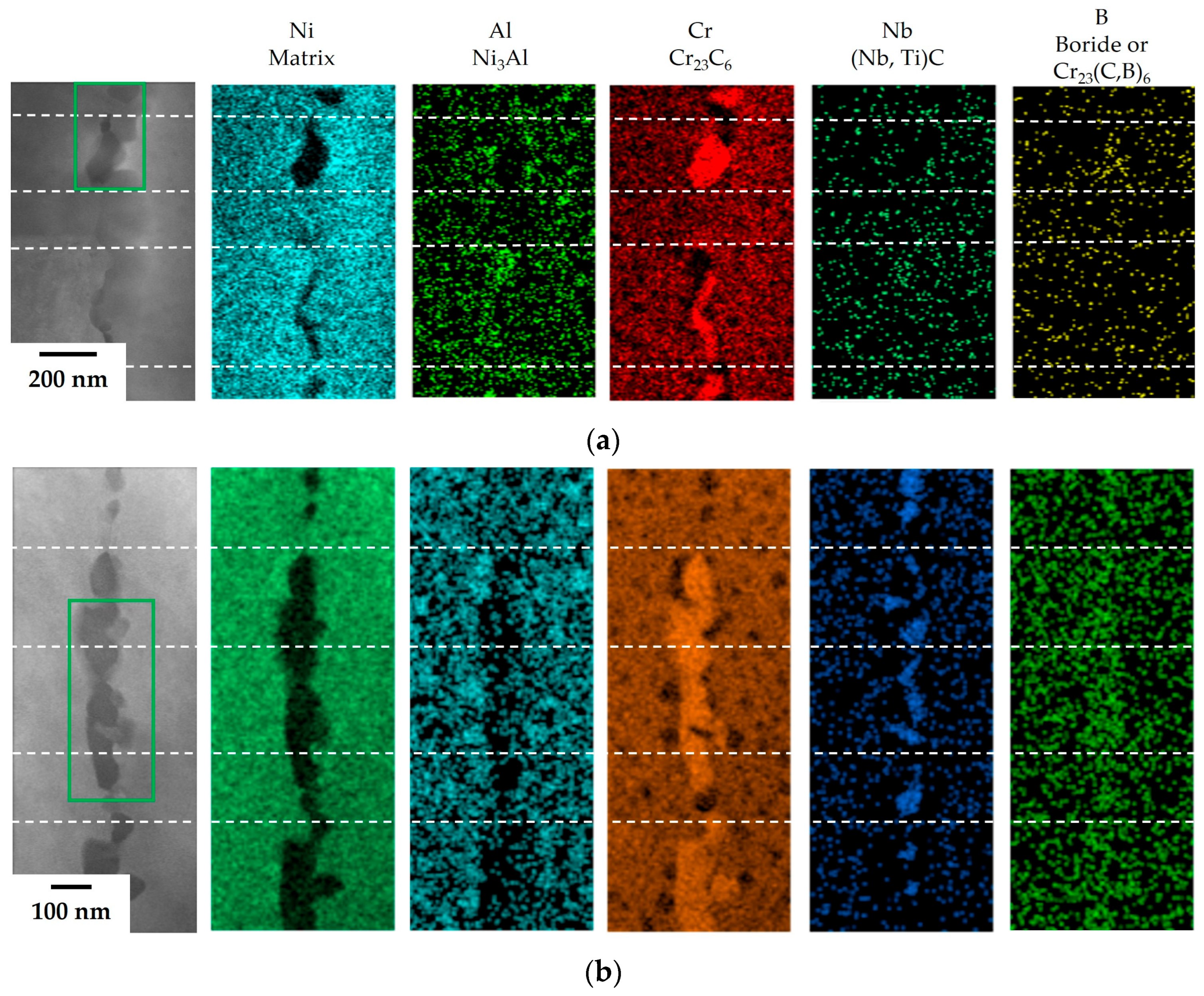
The results of TEM and EDS analysis on the precipitates at the GBs in the 80B and 80B-80Zr alloys are illustrated in
Figure 5. In the 80B alloy, Al– or Cr–rich adjacent areas were observed within the precipitates at the GBs, which were assumed to form the γ’ (Ni
3Al) phases and Cr
23C
6 carbides. The γ’ phases were observed to be approximately 30 nm in diameter, while the Cr
23C
6 carbides exhibited shapes resembling islands and needles, approximately 200 nm in length. The precipitates resulting from the addition of B confirmed a film structure composed of Cr
23C
6 carbides and γ’ phases. In the 80B-80Zr alloy, on the other hand, Al– or Cr–rich adjacent areas were observed and Nb–rich regions were detected between Cr–rich areas. Therefore, the film structure, which was assumed to be constructed upon adding a trace amount of B and Zr, was expected to include γ’ phases, Cr
23C
6, and (Nb, Ti)C carbides at the GBs. The size of the carbides, with Cr
23C
6 being 70 nm and (Nb, Ti)C being 40 nm, is smaller than that of the 80B alloy. Each carbide is distributed alternately within a line in the film structure. However, since B and Zr are only added at a concentration of 100 ppm, they are not detected using EDS. To detect the trace elements within the film structure, an EELS analysis of the carbides along the GBs (green box in
Figure 5) was performed.
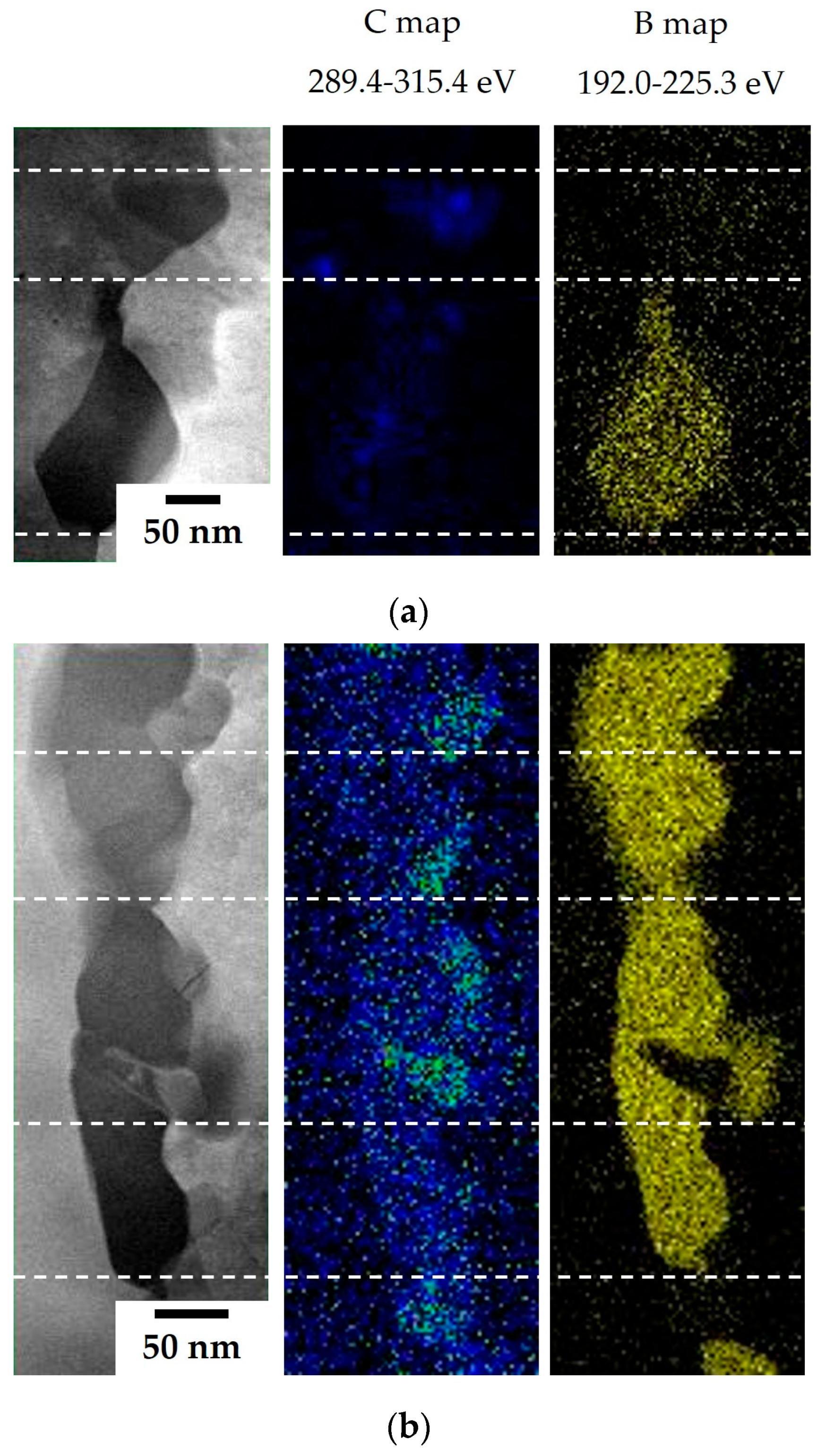
The results of the TEM and EELS analyses on the precipitates are illustrated in
Figure 6. In the 80B alloy, B– and C–rich areas are detected separately (upper area,
Figure 6a) and simultaneously (lower area) within the Cr–rich areas. It is confirmed that not only Cr
23C
6 carbides but also Cr
23(C, B)
6 boro-carbides are formed in the film structure upon the addition of B. In the 80B-80Zr alloy, B and C are detected identically in every Cr–rich area and a strong C signal is detected in the Nb–rich areas. These strong C signals in the Nb–rich areas are indicative of the combination of C and metal atoms, such as (Nb, Ti)C carbides, at a ratio of 1:1. Therefore, it is clarified that the film structure, upon adding a trace amount of B and Zr, includes Cr
23(C, B)
6 boro-carbides, as well as (Nb, Ti)C carbides.
Based on the results of SEM and TEM analyses, the effects of the addition of B and Zr were studied in phase-controlled nickel-based superalloys. However, the precise distribution of B and Zr within the film structure cannot be determined solely from these two-dimensional microstructures. Therefore, the film structure was examined in three dimensions using APT. To ensure the inclusion of various phases in the APT analysis area, the film structure was positioned at the end of nanotips using FIB milling. The processed nanotips are depicted in
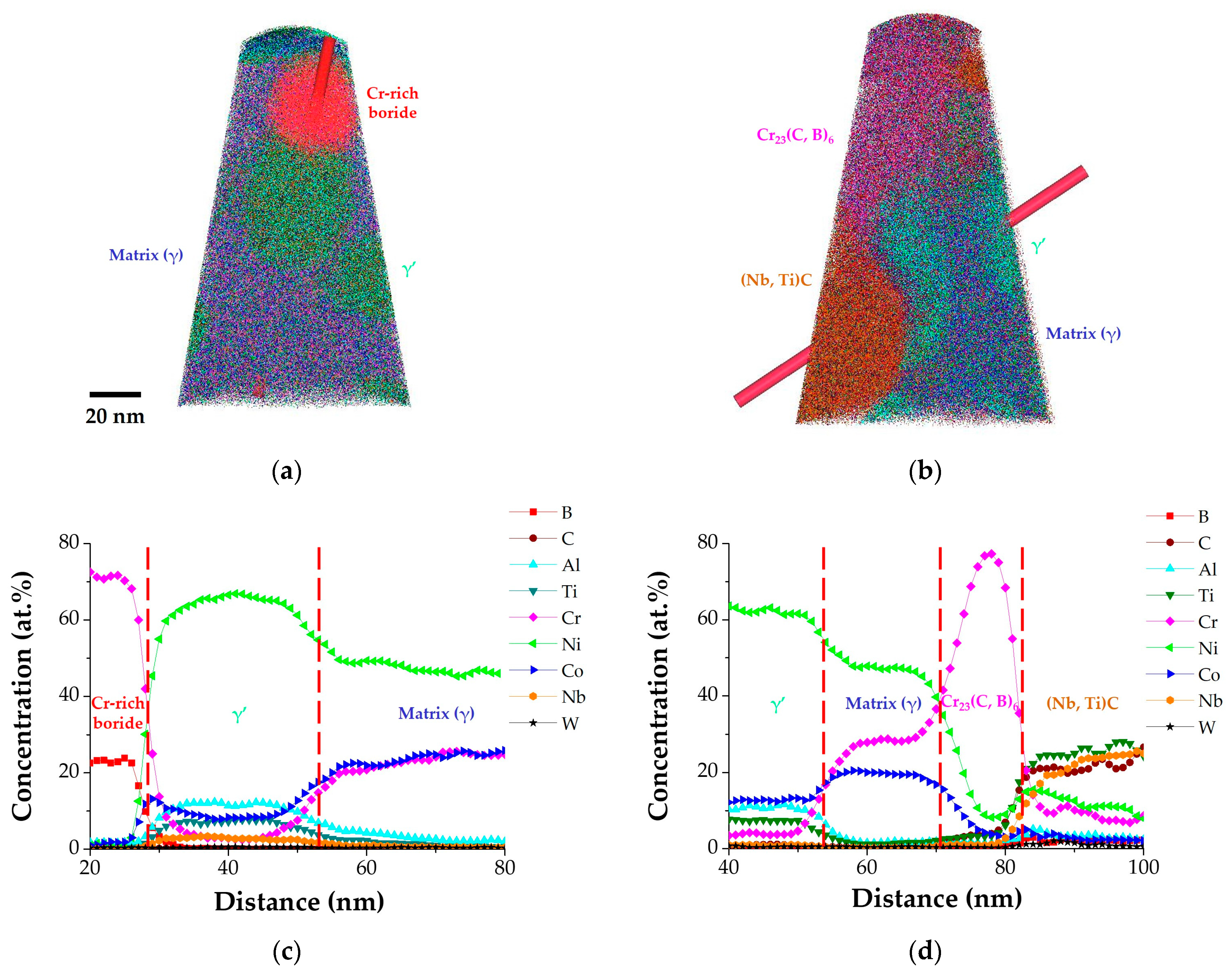
Figure 7, while the APT 3D reconstruction of the nanotips and concentration profile plots along the GBs (i.e., 80B and 80B-80Zr) are presented in
Figure 8.
The reconstruction image is presented with various color areas, including matrix (γ, indigo), γ’ (lime green), Cr
23(C, B)
6 (magenta), (Nb, Ti)C (brown), and Cr–rich boride (red) (
Figure 8a,b). The red cylinder in
Figure 8a,b is a region of interest (ROI) that can create a 1D concentration profile. The concentration gradients of each element within each phase are also depicted (
Figure 8c,d). The color of the phases is determined by mixing the colors of the dominant elements. The 2D images of SEM and TEM show that the film structure consists of carbides, boro-carbides, or both, surrounded by γ’ phases. The reconstruction display of APT could confirm the three-dimensional structure of the film. In the 80B alloy, nanometer-sized Cr–rich boride is also observed in a sphere in
Figure 8a. The discontinuous film structure was confirmed to be constructed of nanometer-sized Cr
23C
6 carbides, Cr
23(C, B)
6 boro-carbides, and Cr–rich borides, surrounded by γ’ phases. In the 80B-80Zr alloy, the continuous film structure of nanometer-sized Cr
23(C, B)
6 boro-carbides and (Nb, Ti)C carbides alternately distributed and surrounded by γ’ phases was reconfirmed.
The results of the creep test, SEM, TEM, and APT confirm that the formation of the film structure significantly increases the creep resistance with the addition of B. Furthermore, when Zr is added along with B, the creep resistance doubles compared to the 80B alloy, attributed to the presence of nanometer-sized Cr
23(C, B)
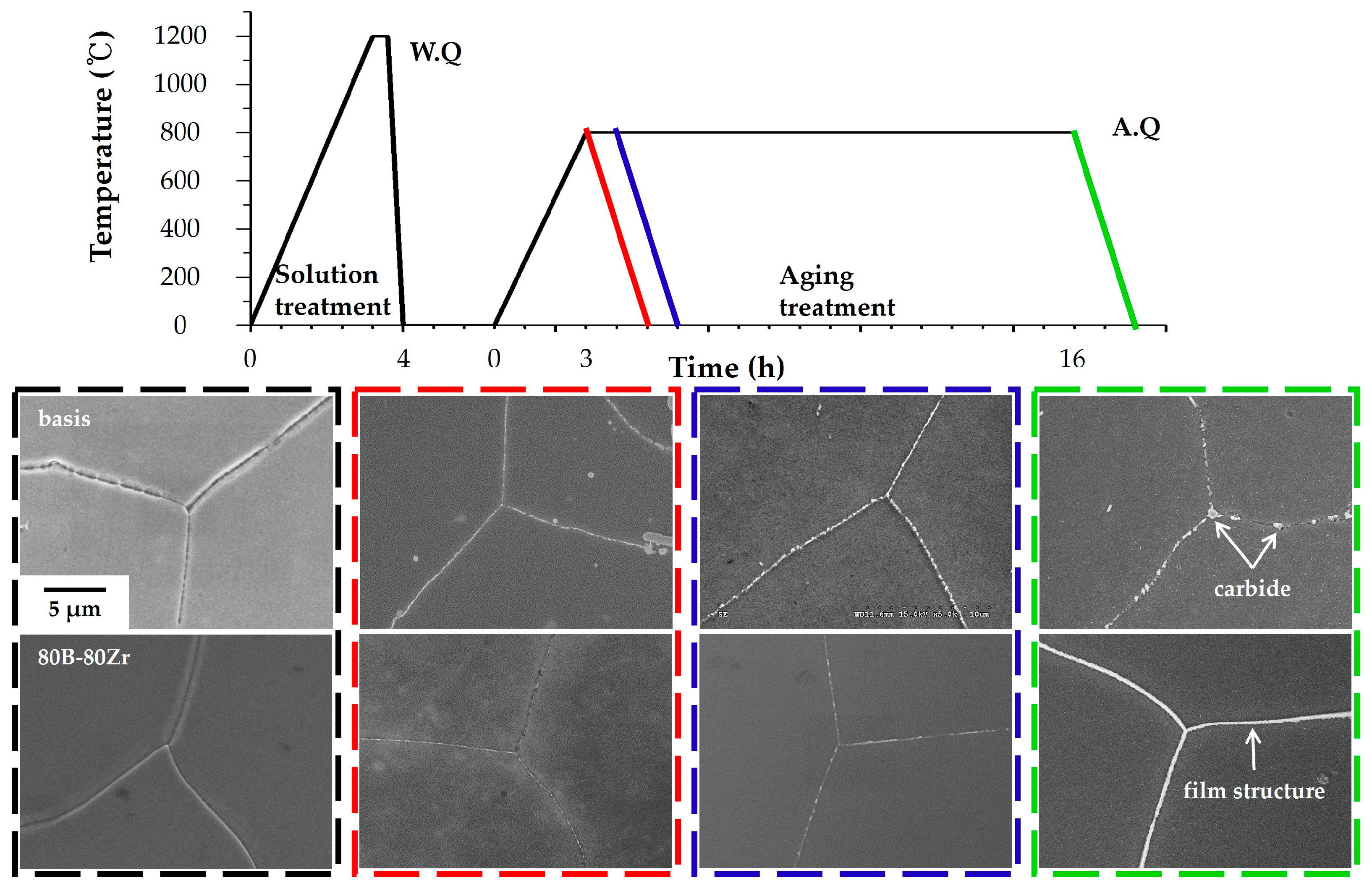
6 and (Nb, Ti)C, forming alternately in the continuous film structure. The film structure is a dominant influence on creep resistance. Therefore, understanding the process of film structure formation during heat treatment is crucial. The results of the microstructural observations regarding the heat treatment stage are presented in
Figure 9.
The schematic graph and SEM images show the stages of heat treatment with color coding, namely after solution treatment (black), aging treatment 0 h (red), 1 h (blue), and 16 h (green). To clarify and compare the formation of the film structure, investigations were conducted on both the basis alloy and the 80B-80Zr alloy. Following solution heat treatment, no precipitates are observed at GBs in either alloy (indicated by the black dashed box). During aging heat treatment, carbide precipitates of the basis alloy quickly form at the GBs, compared to the 80B-80Zr alloy. In the case of the region marked by the red dashed square, despite the basis alloy being heated to 800 °C and then immediately removed without holding and subsequently air-cooled, precipitates are observed in almost every region of the GBs. These precipitates grow and agglomerate during aging heat treatment (blue and green dashed boxes), forming Cr
23C
6 and (Nb, Ti)C carbides of a micrometer-sized island-type structure, as discussed in
Figure 2c and
Figure 3c. It is confirmed that the (Nb, Ti)C or (Nb, Ti, Zr)C carbides at the GBs were not formed during solidification from the melt, but rather through a precipitation reaction during heat treatment in both the basis alloy and the 90Zr alloy. In the 80B-80Zr alloy, numerous nucleation sites of precipitates are also formed along the GBs (red dashed box). However, precipitates grow relatively slowly and do not agglomerate to micrometer-sized (blue and green dashed boxes) and form the continuous film structure, including numerous nanometer-sized precipitates (i.e., Cr
23(C, B)
6 and (Nb, Ti)C in
Figure 5b and
Figure 6b) alternately distributed (green dashed box).
4. Discussion
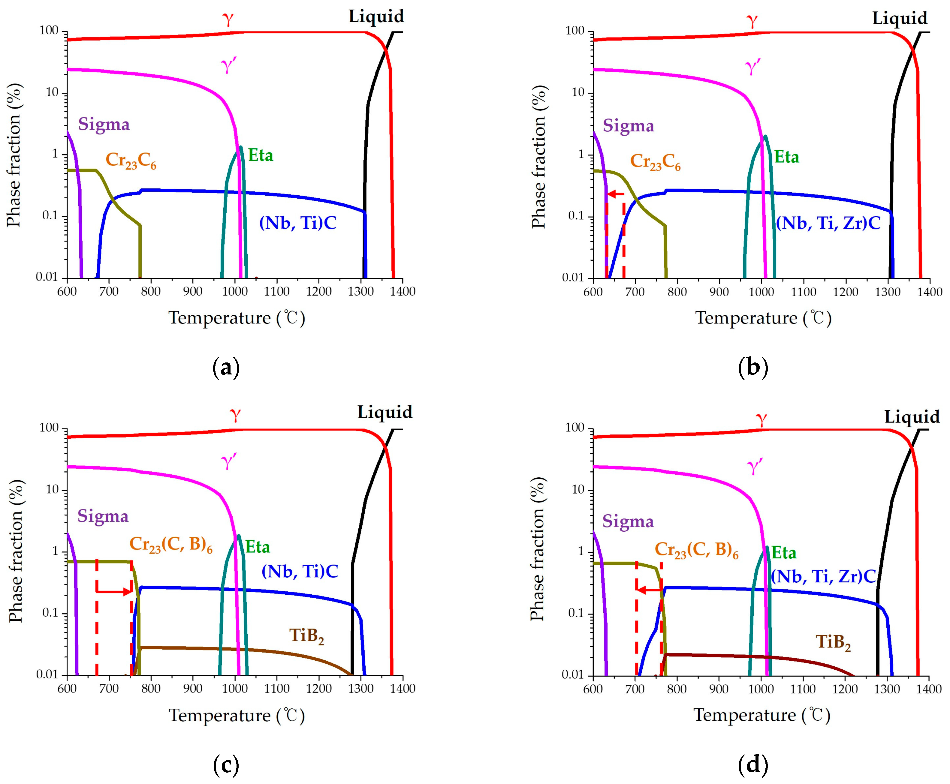
It is well known that the addition of trace amounts of B and Zr increases creep resistance in nickel-based superalloys. Meanwhile, the effect of each trace element has not been fully understood from a microstructural perspective, because the nickel-based superalloy has been combined with various elements for use at high temperatures and oxidation environments. In this study, B and Zr were added at approximately 100 ppm in phase-controlled nickel-based superalloys, affecting the precipitates at the GBs. These experimental results are discussed from the precipitation perspective, with the predicted fraction of stable phases depending on the temperature, using the JMatPro program. The predicted graphs are shown in
Figure 10.
The graph presents liquid (melt), γ, γ’, TCP phases (e.g., eta and sigma), carbide, boro-carbide, and boride. According to experimental results, the addition of a trace amount of B and Zr only changed the microstructure at the GBs. Therefore, the carbide, whose fraction is below 1% but distributed dominantly at the GBs, is focused on and discussed. In the graphs of the 90Zr and 80B-80Zr alloys, MC carbide is calculated and presented as (Nb, Ti, Zr)C. Additionally, in the graphs of the 80B and 80B-80Zr alloys, boride is calculated and presented as MB
2 (TiB
2), but has not been detected in this study. A Ti atom must be consumed to form boride from a calculation point of view. However, from the experimental results, it has been clearly demonstrated that Ti is detected at (Nb, Ti)C carbides or γ’ phases, and B facilitates the formation of the Cr–rich boride or Cr
23(C, B)
6 boro-carbides, rather than contributing to the formation of the TiB
2 phase and this result is consistent with previous studies [
9,
10,
11,
12,
13,
14].
It is reported that the precipitation of NbC carbides is observed during aging treatment and precipitate-free zones (γ’ and γ’’) are formed in adjacent areas in the IN 718 alloy [
30]. Zr is also a strong former of MC carbide [
31] and it transforms from Ti–rich carbide to ZrC at elevated temperatures in the Zr–doped IN 100 alloy [
18]. The 90Zr alloy in this study is similar to the morphology of the basis alloy at the GBs. Adding Zr slightly improves the creep resistance and it increases the fraction of MC carbides (i.e., (Nb, Ti)C and (Nb, Ti, Zr)C) at the GBs, as shown in
Figure 2. Compared with the basis and the 90Zr alloy in the predicted graph, it is generally similar to the experimental results. By adding Zr, the temperature at which the (Nb, Ti, Zr)C carbide was predicted to exist decreased from 670 °C to 640 °C, as presented by the dashed line and arrow in
Figure 10b. It can be evidenced that the fraction of MC carbides (i.e., (Nb, Ti)C and (Nb, Ti, Zr)C) increased during the precipitation reaction.
The 80B alloy significantly increases the creep resistance by forming a film structure, constructed of Cr
23C
6 carbides, Cr
23(C, B)
6 boro-carbides, and Cr–rich borides surrounded with γ’. Added B is segregated into GBs and forms Cr–rich borides or Cr
23(C, B)
6 boro-carbides [
4,
5,
6,
7,
8,
9,
10,
11,
12,
13,
14,
15,
16,
17]. Interestingly, the fraction of carbides is contrary to the 90Zr alloy, as presented by the dashed line and arrow in
Figure 10c. The temperature at which the (Nb, Ti)C carbide was predicted to exist increased from 670 °C to 760 °C and the fraction of Cr
23(C, B)
6 boro-carbides was increased at the same range. These calculated results can explain the precipitation of the film structure without (Nb, Ti)C carbide at the GBs, as shown in
Figure 4. Because the (Nb, Ti)C carbide does not form at the GBs, co-segregated C and B in certain areas actively react with Cr to form the Cr
23C
6 carbides, Cr
23(C, B)
6 boro-carbides, and Cr–rich borides. Nb and Ti, concentrated in the adjacent area, combine with Ni and Al to form the γ’ phase. Therefore, the film structure is partially distributed along the GBs. It is well known that the creep-resistant property is decreased by precipitation of near-continuous carbides, but is increased by the formation of film structure with carbides and γ’ phases [
29].
Film structures, constructed of numerous nanometer-sized precipitates, (Cr
23(C, B)
6 boro-carbides, and (Nb, Ti)C carbides), alternately distributed and surrounded by γ’ phases, are formed continuously in the 80B-80Zr alloy; the rupture time of the 80B-80Zr alloy was measured to be twice that of the 80B alloy. A synergy effect occurred with the addition of B and Zr, as presented in
Figure 10d. The fraction of Cr
23(C, B)
6 carbides is similar to that of the 80B alloy; the temperature at which (Nb, Ti)C carbides were predicted to exist decreased from 760 °C to 700 °C. As is observed from the microstructure in
Figure 9, numerous nucleation sites of precipitates formed along every GB in the 80B-80Zr alloy. These precipitates grew to numerous nanometer-sized Cr
23(C, B)
6 boro-carbides (70 nm) and (Nb, Ti)C carbides (40 nm), distributed alternately in the film structure (
Figure 5b and
Figure 6b). Considering the result of the calculation and the observed microstructure, it is confirmed that segregated B combines with Cr and C to form the nucleation site of the Cr
23(C, B)
6 boro-carbide, and Zr affects Nb, Ti, and C to nucleate the precipitate sites of the (Nb, Ti)C carbide. Nucleation sites are formed alternately and simultaneously and grow to a nanometer size until facing each other at the GBs. The creep-resistant property is improved by forming the continuous film structure constructed with numerous nanometer-sized precipitates and GB γ’ phases. Consequentially, the effect of the addition of B and Zr is such that the nucleation sites of Cr
23(C, B)
6 boro-carbide and (Nb, Ti)C carbide are formed alternately and simultaneously during the precipitation reaction in the 80B-80Zr alloy.
