Communication

Machinability of MoS2 after Oxygen Plasma Treatment under Mechanical Scanning Probe Lithography

1
Shenzhen Key Laboratory of Cross-Scale Manufacturing Mechanics, Southern University of Science and Technology, Shenzhen 518055, China
2
SUSTech Institute for Manufacturing Innovation, Southern University of Science and Technology, Shenzhen 518055, China
3
Department of Mechanics and Aerospace Engineering, Southern University of Science and Technology, Shenzhen 518055, China
4
Sichuan Precision and Ultra-Precision Machining Engineering Technology Center, Chengdu 610200, China
*
Authors to whom correspondence should be addressed.
Crystals 2024, 14(3), 280; https://doi.org/10.3390/cryst14030280
Submission received: 1 March 2024 / Revised: 10 March 2024 / Accepted: 13 March 2024 / Published: 15 March 2024
(This article belongs to the Section Inorganic Crystalline Materials)

Abstract

:
The surface of molybdenum disulfide (MoS2) underwent oxygen plasma treatment to enhance its machinability and mitigate the tearing effects commonly associated with mechanical forces on 2D materials. This treatment led to the oxidation of the atoms on the top 1–3 layers of MoS2, resulting in the formation of MoO3 on the surface. During mechanical scanning probe lithography (m-SPL), only the surface oxide layer was uniformly removed, with material accumulation occurring predominantly on one side of the machined area. The resolution of the machining process was significantly enhanced via dynamic lithography while maintaining atomic-level smoothness in the machined area. Importantly, these techniques only removed the surface oxide layer, preserving the integrity of the underlying MoS2 surface, which was pivotal in avoiding damage to the original material structure. This study provided valuable insights and practical guidance for the nanofabrication of transition metal dichalcogenides (TMDCs) nanodevices, demonstrating a method to finely tune the machining of these materials.

1. Introduction

In recent years, 2D transition metal dichalcogenides (TMDCs) have gained significant attention for their use in nanoelectronics, optoelectronics, biosensing and other applications, due to their excellent optical, electrical, and mechanical properties [1,2,3,4]. However, a challenge in device fabrication involving these 2D materials is the difficulty in removing photoresists or electron beam lithography resists. These residues impaired the performance of the fabricated devices [5,6,7]. To address this, post-lithography methods like thermal annealing, solvent rinsing or plasma cleaning were employed to remove resist residues, enhance surface passivation, and improve metal–semiconductor contacts [8,9,10]. It remains challenging to develop techniques that effectively prevent the accumulation of surface residues on 2D material surfaces.
Within this context, scanning probe nanolithography (SPL) has emerged as a potent and resist-free lithographic technique, providing precise nanoscale accuracy and direct patterning capabilities on TMDCs [11,12,13,14,15]. Notably, mechanical scanning probe lithography (m-SPL), the fundamental method of SPL, involved directly applying force to remove material from a surface. A few defects were formed on molybdenum disulfide (MoS2) surfaces under nano-scratching, especially around the edges of the nanogrooves [16]. Consequently, two distinctive types of cracks were observed on the MoS2 surfaces [17]: semi-circular cracks at the fracture front and periodical zigzag cracks in the middle. The anisotropic nature of these cracks during their formation and propagation contributed to a reduction in the quality of the nanofabrication process, posing challenges for the integrity and performance of the resultant nanodevices. On the basis of ensuring nanofabrication resolution, it is particularly important to further enhance the machinability of mechanical scanning probe lithography.
The objective of this letter is to explore the machinability of MoS2 after oxygen plasma treatment when subjected to mechanical scanning probe lithography. After the application of an oxygen plasma treatment, a uniform oxide layer is formed on MoS2 flake. We will employ atomic force microscopy (AFM) for nano-scratching and dynamic lithography on these oxide-coated flakes. Our aim is to elucidate the characteristics of material removal, thereby contributing valuable insights to nanofabrication techniques for TMDC surfaces. This understanding is crucial for developing nanomachining processes tailored to these materials for the advancement of nanoscale devices.

2. Materials and Methods

2.1. Oxygen Plasma Treatment

In this study, few-layer flakes of MoS2 (SPI supplies, West Chester, PA, USA) were produced, which were mechanically exfoliated using adhesive tape and subsequently transferred onto SiO2/Si substrates, as depicted in Figure 1a. For this transfer, commercially available viscoelastic polydimethylsiloxane (PDMS) films (Gelfilm, Gel-Pak, Hayward, CA, USA) were employed. After the preparation of few-layer MoS2 flakes, the flakes were treated by oxygen plasma under a low-pressure plasma system (Tetra, Diener electronic GmbH, Ebhausen, Germany), with an applied power of 200 W for a duration of 1 min, as shown in Figure 1b.

2.2. Mechanical Scanning Probe Lithography

The scanning probe lithography experiments were conducted using a commercial AFM system (Dimension Icon, Bruker Corporation, Billerica, MA, USA). The equipped Nanoman module in the AFM system is utilized for the scratching process in this study. Figure 1c illustrates the schematic of the lithography processes. To carry out the nanomachining on MoS2 flakes, a silicon tip (MPP-11120, Bruker Corporation, Billerica, MA, USA) with a nominal spring constant of 40 N/m was utilized. During the nano-scratching process in contact mode, the cantilever deformation was regulated by the voltage of the laser on the photodetector (Vsetpoint), influencing the applied normal load. In tapping mode, the driven amplitude Vr (reading voltage) was obtained by actuating the cantilever at its resonant frequency. For dynamic lithography, the cantilever of the AFM tip was driven to Vw (writing voltage). The driven amplitude ratio Vw/Vr was maintained in the range of 5–25 under dynamic lithography. The direction of m-SPL was perpendicular to the long axis of the cantilever. Post-nanogroove fabrication, a new silicon tip was used to assess the morphology of the generated nanogroove under tapping mode. The scan rate was set at 1 Hz with each scan line comprising 256 pixels. The resulting AFM images were processed using Nanoscope Analysis 1.90 software (Version) provided by Bruker Company.

3. Results and Discussion

3.1. MoS2 Nanosheets under Oxygen Plasma Treatment

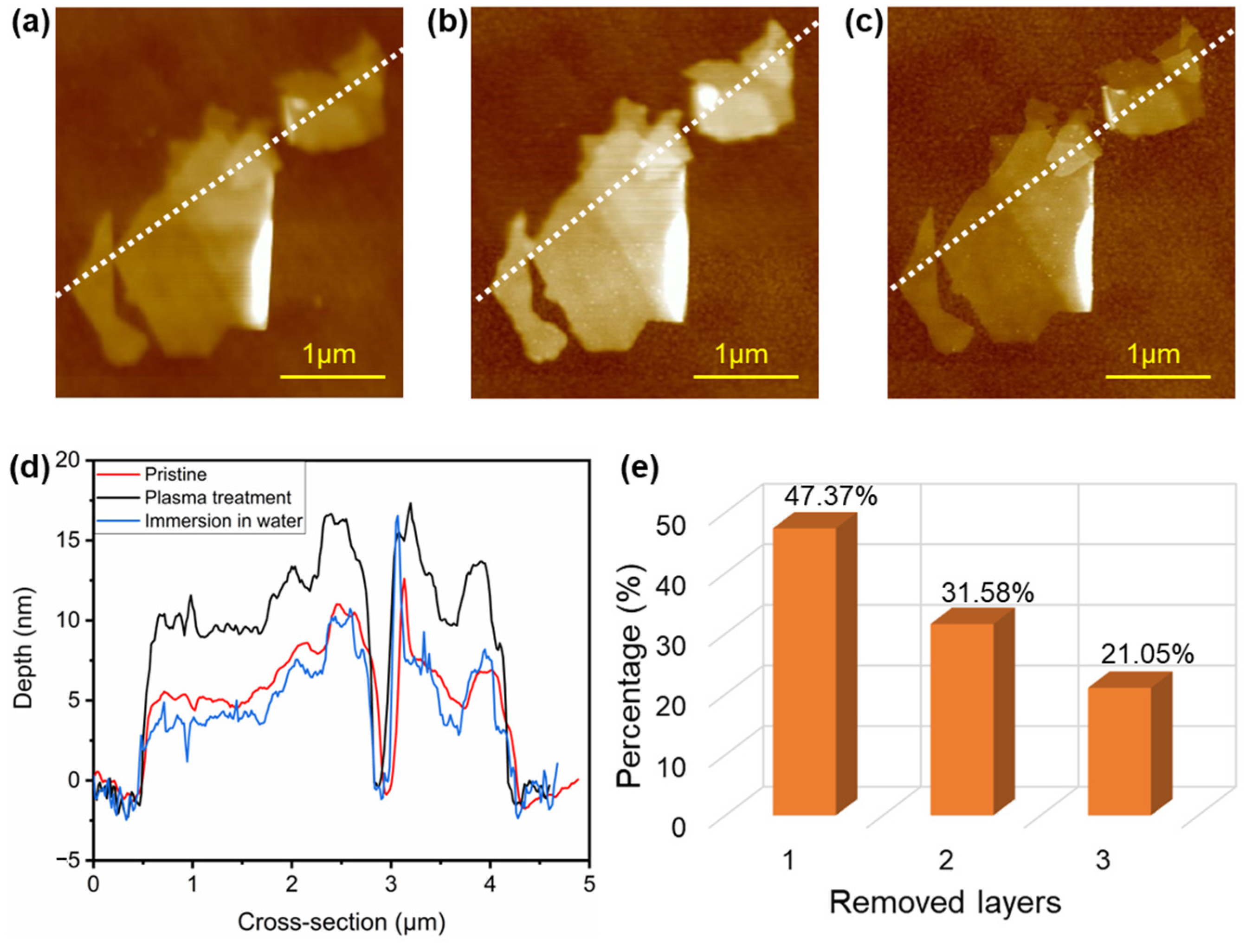
The optical microscope was initially used to locate the position of the flakes, followed by precise positioning using the AFM tip. After the preparation of few-layer MoS2 flakes through mechanical exfoliation, one flake surface was analyzed, as illustrated in Figure 2a. Subsequently, the surface was treated with oxygen plasma, resulting in the oxidized surface depicted in Figure 2b. An essential step in this process was measuring identical flakes along the same cross-sections. By comparing AFM images before and after oxygen plasma treatment, as shown in Figure 2a,b, it is indicated that the surface height of MoS2 flakers increased in the range from 4 to 5 nm, according to cross-sections of the pristine flakes of the surface with plasma treatment in Figure 2d, which confirms that the oxidation layer formed was MoO3 [18,19]. To measure the thickness of the oxidation layer, the produced oxidation was soluble in water, as indicated in Figure 2c. The resulting flake was about 1–2 nm thinner than the pristine flake, based on the heights of the flake after immersion in water for 30 s, as shown in Figure 2d. The same processes were performed on 19 flakes, and it was found that after being treated in oxygen plasma, 1 to 3 layers of MoS2 were oxidized based on statistics data in Figure 2e, corresponding to the Raman spectroscopy analysis [20]. The oxygen plasma treatment process produced reactive particles, which resulted in thinning the surface through physical bombardment. Note that the oxygen plasma treatment process produced an oxidation phenomenon in this study. The surface, after the oxygen plasma treatment, was relatively flat, which is suitable for mechanical scanning probe lithography.

3.2. Comparation between Nano-Scratching and Dynamic Lithography

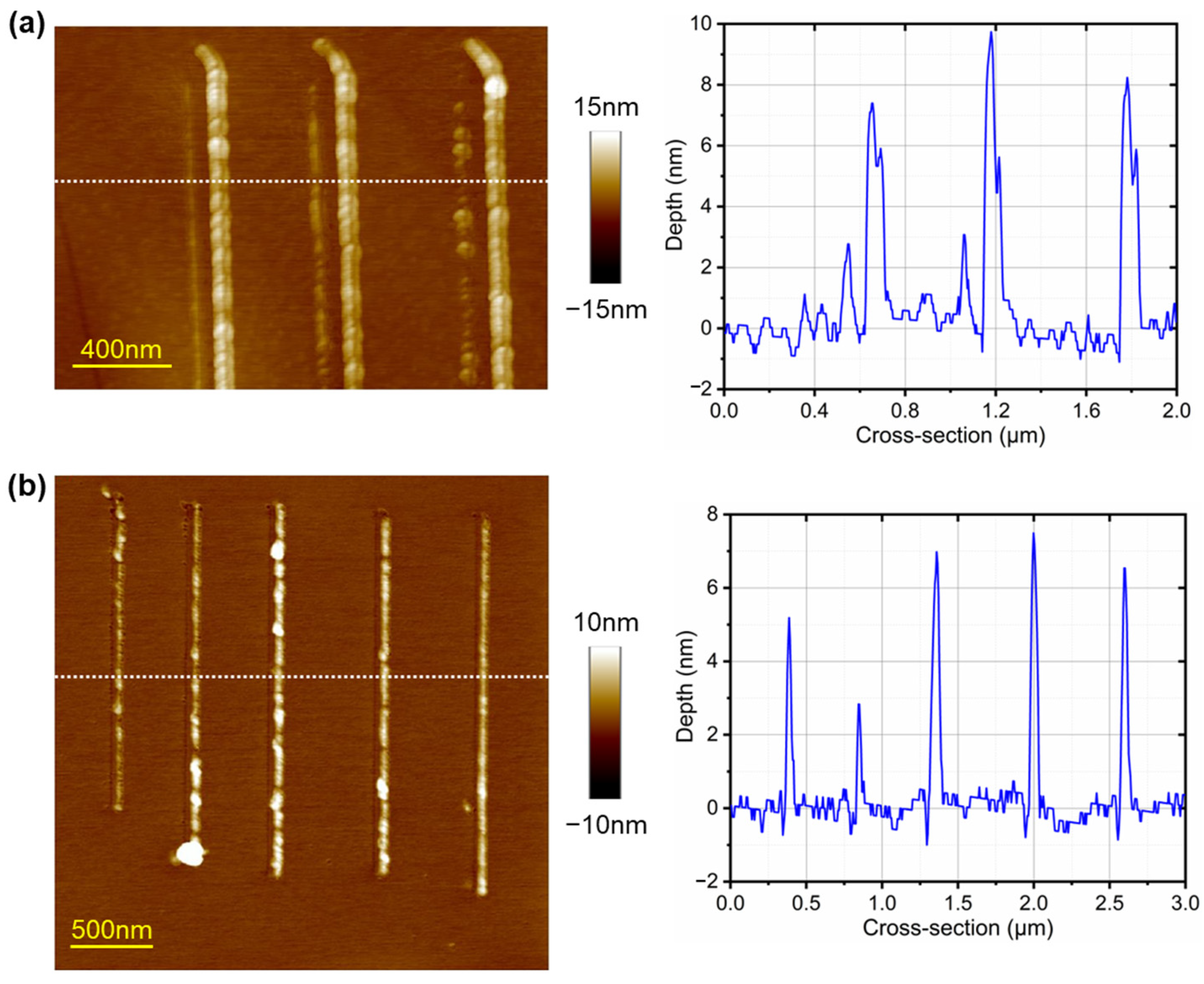
Following the oxygen plasma treatment on the MoS2 surface, nano-scratching was conducted in AFM contact mode with the voltage bias from 1 to 3 V. As shown in Figure 3a, it was found that the nanogrooves were processed under the mechanical load, and the removed surface materials were accumulated around the nanogrooves. The fabrication results indicated that the process led to plastic deformation without causing any cracks. The width and depth of the nanogrooves were measured to be about 55 nm and 0.88 ± 0.17 nm, respectively. And the machined depth remained consistent even as the mechanical load increased. This process effectively removed the oxide layer, exposing the original MoS2 flake. An additional shallower groove surrounding the main grooves may have resulted from a defect in the AFM tip. To further enhance the resolution of m-SPL, a dynamic lithography technique was employed. As depicted in Figure 3b, the nanogrooves were produced when the driven amplitude ratio varied from 5 to 25. The cyclic extrusion of the tip not only removed the oxide layer but also led to the formation of material pileups. The machined depth was around 1.30 ± 0.47 nm, and it remained stable across different driven amplitude settings. The month width was roughly 23 nm, showcasing the capability of dynamic lithography in achieving high-resolution nanofabrication on TMDCs surfaces. Therefore, the application of the oxidation treatment enhanced the machinability of the MoS2 surface, effectively preventing the formation of uncontrolled cracks [17] due to mechanical stress. And the tearing of the 2D surface [21] was prevented during dynamic lithography. The treated surface also exhibited isotropic properties, as discussed in [20], enhancing the overall quality and consistency of the nanofabrication process. In the future, it is worth further investigating methods to eliminate material pileups.

3.3. Characterization on Nanofabrication Quality of Dynamic Lithography

Dynamic lithography was utilized for high-resolution nanomachining. The nanofabrication quality should be further assessed. Figure 4 displays the surface morphologies and the corresponding cross-sections of the machined areas via dynamic lithography at the driven amplitude ratio of 10, 15 and 20. The results showed uniform material removal from the surface, with minimal material debris remaining at the edges. Most of the removed material accumulated at the end of the tip trace. The machined depth varied from 0.96 to 2.21 nm, corresponding to approximately 1 to 3 layers of MoS2 thickness. Additionally, Figure 4 includes phase images of the machined areas, which could be employed to explore the influence on the mechanical properties of 2D materials at the nanoscale through contact stiffness measurements [22]. To verify that the observed phase contrast was not due to topographic changes, the phase measurements were taken in both forward and backward scanning directions. The consistency in these measurements across both directions confirmed the material contrast, indicating successful removal of the surface oxidation layer and exposure of the pristine MoS2 surface. The surface roughness of both the machined area and the original surface was quantified, as shown in Table 1. It was observed that the surface roughness of the machined area was marginally higher than that of the original surface. Nevertheless, the resulting surface was atomically flat, demonstrating that the dynamic lithography technique yielded high-quality surface nanomachining.

4. Conclusions

This study has investigated the material removal capabilities of MoS2 after oxygen plasma treatment under mechanical scanning probe lithography. Oxygen plasma treatment enhanced the MoS2 surface’s machinability. Under this condition, the surface material could be precisely removed using techniques like nano-scratching and dynamic lithography. Notably, dynamic lithography demonstrated superior machining resolution and maintained surface integrity more effectively. The surface oxide layer was selectively removed by nanomachining, exposing the untouched MoS2 surface without causing any damage. This resulted in a machined surface with atomic-level smoothness for the fabrication of subsequent nanodevices.

Author Contributions

Conceptualization, Y.H., X.S. and K.H.; methodology, Y.H.; validation, Y.H., X.S. and K.H.; formal analysis, Y.H.; investigation, Y.H.; data curation, Y.H.; writing—original draft preparation, Y.H.; writing—review and editing, X.S. and K.H.; funding acquisition, Y.H., X.S. and K.H. All authors have read and agreed to the published version of the manuscript.

Funding

The authors gratefully acknowledge the financial support of the National Natural Science Foundation of China Project 52105488 and 52293401, Shenzhen Key Laboratory of Cross-Scale Manufacturing Mechanics Project ZDSYS20200810171201007 and Shenzhen Science and Technology Program Project RCBS20210706092216025.

Data Availability Statement

The original contributions presented in the study are included in the article. Further inquiries can be directed to the corresponding author.

Conflicts of Interest

The authors declare no conflicts of interest.

References

  1. Radisavljevic, B.; Radenovic, A.; Brivio, J.; Giacometti, V.; Kis, A. Single-layer MoS2 transistors. Nat. Nanotechnol. 2011, 6, 147–150. [Google Scholar] [CrossRef] [PubMed]
  2. Hu, Z.; Wu, Z.; Han, C.; He, J.; Ni, Z.; Chen, W. Two-dimensional transition metal dichalcogenides: Interface and defect engineering. Chem. Soc. Rev. 2018, 47, 3100–3128. [Google Scholar] [CrossRef] [PubMed]
  3. Fathi-Hafshejani, P.; Azam, N.; Wang, L.; Kuroda, M.A.; Hamilton, M.C.; Hasim, S.; Mahjouri-Samani, M. Two-dimensional-material-based field-effect transistor biosensor for detecting COVID-19 Virus (SARS-CoV-2). ACS Nano 2021, 15, 11461–11469. [Google Scholar] [CrossRef]
  4. Park, H.; Park, J.; Kang, S.; Jeong, S. 3D-nanostructured MoS2 nanoscroll with highly active sites for improving NO2 gas detection. Mater. Lett. 2023, 349, 134733. [Google Scholar] [CrossRef]
  5. Liang, J.; Xu, K.; Toncini, B.; Bersch, B.; Jariwala, B.; Lin, Y.; Robinson, J.; Fullerton-Shirey, S.K. Impact of post-lithography polymer residue on the electrical characteristics of MoS2 and WSe2 field effect transistors. Adv. Mater. Interfaces 2019, 6, 1801321. [Google Scholar] [CrossRef]
  6. Jia, Y.; Gong, X.; Peng, P.; Wang, Z.; Tian, Z.; Ren, L.; Fu, Y.; Zhang, H. Toward high carrier mobility and low contact resistance: Laser cleaning of PMMA residues on graphene surfaces. Nano-Micro Lett. 2016, 8, 336–346. [Google Scholar] [CrossRef] [PubMed]
  7. Suk, J.W.; Lee, W.H.; Lee, J.; Chou, H.; Piner, R.D.; Hao, Y.; Akinwande, D.; Ruoff, R.S. Enhancement of the electrical properties of graphene grown by chemical vapor deposition via controlling the effects of polymer residue. Nano Lett. 2013, 13, 1462–1467. [Google Scholar] [CrossRef] [PubMed]
  8. Choi, J.; Zhang, H.; Du, H.; Choi, J.H. Understanding solvent effects on the properties of two-dimensional transition metal dichalcogenides. ACS Appl. Mater. Interfaces 2016, 8, 8864–8869. [Google Scholar] [CrossRef]
  9. Thoutam, L.R.; Mathew, R.; Ajayan, J.; Tayal, S.; Nair, S.V. A critical review of fabrication challenges and reliability issues in top/bottom gated MoS2 field-effect transistors. Nanotechnology 2023, 34, 232001. [Google Scholar] [CrossRef]
  10. Tilmann, R.; Bartlam, C.; Hartwig, O.; Tywoniuk, B.; Dominik, N.; Cullen, C.P.; Peters, L.; Stimpel-Lindner, T.; McEvoy, N.; Duesberg, G.S. Identification of ubiquitously present polymeric adlayers on 2D transition metal dichalcogenides. ACS Nano 2023, 17, 10617–10627. [Google Scholar] [CrossRef]
  11. Chang, S.; Yan, Y.; Geng, Y. Local nanostrain engineering of monolayer MoS2 using atomic force microscopy-based thermomechanical nanoindentation. Nano Lett. 2023, 23, 9219–9226. [Google Scholar] [CrossRef] [PubMed]
  12. Zheng, X.; Calò, A.; Albisetti, E.; Liu, X.; Alharbi, A.S.M.; Arefe, G.; Liu, X.; Spieser, M.; Yoo, W.J.; Taniguchi, T.; et al. Patterning metal contacts on monolayer MoS2 with vanishing Schottky barriers using thermal nanolithography. Nat. Electron. 2019, 2, 17–25. [Google Scholar] [CrossRef]
  13. Dago, A.I.; Ryu, Y.K.; Palomares, F.J.; Garcia, R. Direct patterning of p-type-doped few-layer WSe2 nanoelectronic devices by oxidation scanning probe lithography. ACS Appl. Mater. Interfaces 2018, 10, 40054–40061. [Google Scholar] [CrossRef] [PubMed]
  14. Li, J.; Yi, S.; Wang, K.; Liu, Y.; Li, J. Alkene-catalyzed rapid layer-by-layer thinning of black phosphorus for precise nanomanufacturing. ACS Nano 2022, 16, 13111–13122. [Google Scholar] [CrossRef] [PubMed]
  15. Rani, E.; Wong, L.S. High-resolution scanning probe nanolithography of 2D materials: Novel nanostructures. Adv. Mater. Technol. 2019, 4, 1900181. [Google Scholar] [CrossRef]
  16. Khac, B.T.; DelRio, F.W.; Chung, K. Interfacial strength and surface damage characteristics of atomically thin h-BN, MoS2, and graphene. ACS Appl. Mater. Interfaces 2018, 10, 9164–9177. [Google Scholar] [CrossRef] [PubMed]
  17. Ye, S.; Xu, K.; Lei, L.; Hussain, S.; Pang, F.; Liu, X.; Zheng, Z.; Ji, W.; Shi, X.; Xu, R.; et al. Nanoscratch on single-layer MoS2 crystal by atomic force microscopy: Semi-circular to periodical zigzag cracks. Mater. Res. Express 2019, 6, 025048. [Google Scholar] [CrossRef]
  18. Zhang, Y.; Liu, J.; Pan, Y.; Luo, K.; Yu, J.; Zhang, Y.; Jia, K.; Yin, H.; Zhu, H.; Tian, H.; et al. The evolution of MoS2 properties under oxygen plasma treatment and its application in MoS2 based devices. J. Mater. Sci. Mater. Electron. 2019, 30, 18185–18190. [Google Scholar] [CrossRef]
  19. Pei, C.; Li, X.; Fan, H.; Wang, J.; You, H.; Yang, P.; Wei, C.; Wang, S.; Shen, X.; Li, H. Morphological and spectroscopic characterizations of monolayer and few-layer MoS2 and WSe2 nanosheets under oxygen plasma treatment with different excitation power: Implications for modulating electronic properties. ACS Appl. Nano Mater. 2020, 3, 4218–4230. [Google Scholar] [CrossRef]
  20. Ryu, Y.K.; Dago, A.I.; He, Y.; Espinosa, F.M.; Lopez-Elvira, E.; Munuera, C.; Garcia, R. Sub-10 nm patterning of few-layer MoS2 and MoSe2 nanolectronic devices by oxidation scanning probe lithography. Appl. Surf. Sci. 2021, 539, 148231. [Google Scholar] [CrossRef]
  21. Vasić, B.; Kratzer, M.; Matković, A.; Nevosad, A.; Ralević, U.; Jovanović, D.; Ganser, C.; Teichert, C.; Gajić, R. Atomic force microscopy based manipulation of graphene using dynamic plowing lithography. Nanotechnology 2013, 24, 015303. [Google Scholar] [CrossRef]
  22. Vasić, B.; Matković, A.; Gajić, R. Phase imaging and nanoscale energy dissipation of supported graphene using amplitude modulation atomic force microscopy. Nanotechnology 2017, 28, 465708. [Google Scholar] [CrossRef]
Figure 1. (a) Mechanical exfoliation of MoS2 flakes from bulk crystal. (b) MoS2 flakes treated by oxygen plasma. (c) Mechanical scanning probe lithography on MoS2 flakes after oxygen plasma treatment, including nano-scratching and dynamic lithography.
Crystals 14 00280 g001
Figure 2. AFM images of a MoS2 flake: (a) pristine flake obtained from mechanical exfoliation, (b) after oxygen plasma treatment and (c) after immersion in water for 30 s. (d) Cross-sections of the flakes in (ac) marked in white. (e) Removal layers of MoS2 flakes treated with oxygen plasma and DI water.
Crystals 14 00280 g002
Figure 3. AFM images and the corresponding cross-sections of nanogrooves marked in white on a MoS2 flake with oxygen plasma treatment under (a) nano-scratching and (b) dynamic lithography.
Crystals 14 00280 g003
Figure 4. AFM images and the corresponding cross-sections of fabrication results marked in white under dynamic lithography with the driven amplitude ratio Vw/Vr of (a) 10, (b) 15 and (c) 20.
Crystals 14 00280 g004
Table 1. Roughness of unmachined surface and machined surface after dynamic lithography with varied driven amplitude ratio.
Vw/VrUnmachined Surface Ra (nm)Machined Surface Ra (nm)
100.130.17
150.200.31
200.190.21
Disclaimer/Publisher’s Note: The statements, opinions and data contained in all publications are solely those of the individual author(s) and contributor(s) and not of MDPI and/or the editor(s). MDPI and/or the editor(s) disclaim responsibility for any injury to people or property resulting from any ideas, methods, instructions or products referred to in the content.