Article

Uncommon Cold-Rolling Faults in an Fe–Mn–Si–Cr Shape-Memory Alloy

by
Gheorghe Bădărău
1,
Mihai Popa
1,
George Stoian
2,
Ana-Maria Roman
1,
Radu-Ioachim Comăneci
1,
Bogdan Pricop
1,
Nicanor Cimpoeșu
1 and
Leandru-Gheorghe Bujoreanu
1,*
1
Faculty of Materials Science and Engineering, “Gheorghe Asachi” Technical University of Iași, Blvd. Dimitrie Mangeron 71A, 700050 Iași, Romania
2
National Institute of Research and Development for Technical Physics, Blvd. Dimitrie Mangeron 47, 700050 Iași, Romania
*
Author to whom correspondence should be addressed.
Crystals 2024, 14(3), 250; https://doi.org/10.3390/cryst14030250
Submission received: 18 February 2024 / Revised: 27 February 2024 / Accepted: 1 March 2024 / Published: 2 March 2024
(This article belongs to the Special Issue Microstructure and Properties of Steels and Other Structural Alloys)

Abstract

:
The paper analyzes the occurrence of evenly spaced cracks on the surface of lamellar specimens of Fe-28Mn-6Si-5Cr (mass %) shape-memory alloy (SMA), during cold rolling. The specimens were hot rolled and normalized and developed cold rolling cracks with an approximate spacing of about 1.3 mm and a depth that increased with the thickness-reduction degree. At normalized specimens, X-ray diffraction patterns revealed the presence of multiple crystallographic variants of brittle α′ body-bcc martensite, which could be the cause of cold-rolling cracking. Both normalized and cold-rolled specimens were analyzed using scanning electron microscopy SEM. SEM micrographs revealed the presence of several crystallographic variants of α′-body-centered cubic (bcc) and ε hexagonal close-packed (hcp) martensite plates within a γ-face-centered cubic (fcc) austenite matrix in a normalized state. High-resolution SEM, recorded after 25% thickness reduction by cold-rolling, emphasized the ductile character of the cracks by means of an array of multiple dimples. After additional 33% cold-rolling thickness reduction, the surface of crack walls became acicular, thus revealing the fragile character of failure. It has been argued that the specimens cracked in the neutral point but preserved their integrity owing to the ductile character of γ-fcc austenite matrix.

1. Introduction

Shape-memory materials are a class of intelligent materials able to recover a previous shape they had in their thermomechanical history [1]. The shape recovery phenomenon can be triggered in alloys, ceramics, polymers, composites or hydrides by various stimuli such as mechanical stress, temperature, magnetic field, irradiation, pH change and pressure, etc. [2].
In the specific case of shape-memory alloys (SMAs), the microstructural mechanism of shape recovery is a reversible martensitic transformation that can be thermally, mechanically or magnetically induced [3].
The existence of a reversible thermally induced martensitic transformation, between a high-temperature (parent) phase called austenite and a low-temperature phase called martensite, is a necessary yet not sufficient condition for the occurrence of the shape-memory effect (SME) associated with the thermal memory [4]. The SMA, with a “hot shape” induced in the high temperature austenitic domain, has to be cooled to the martensitic domain, deformed into a “cold shape” to form stable stress-induced martensite, and heated to recover its hot shape. SME represents the unique recovery of the hot shape, by heating an SMA that was previously deformed into a stable cold shape [5]. Essentially, the microscopic reversion that causes the transformation of the unit cell of stress-induced martensite into that of austenite is accompanied by shape recovery at the macroscopic level. One has to note that no SME can be obtained if the SMA cannot be deformed into a stable “cold shape” different from the “hot” one [6].
All the above transitions define “thermal memory” by means of SME, caused by thermal stimuli. But, besides thermal stimuli, there are also mechanical and magnetic stimuli able to trigger specific types of martensitic transformations [7].
The former is stress-induced, produces an unstable martensite and is responsible for the occurrence of the superelasticity phenomenon, characterized by isothermal recovery strains as high as 25%, during mechanical unloading [8].
The latter is caused by the overlapping of thermally and magnetically induced transformations which can produce large magnetic-field-induced strains (typically 8%) and high response frequencies [9].
It is generally accepted that three SMA systems have become commercially used: (i) NiTi-based, (ii) Cu-based and (iii) Fe-based systems [10]. While NiTi-based SMAs are considered “pivotal smart materials” [11], they are rather expensive and difficult to machine due to several drawbacks such as excessive tool wear, adverse chip form or the formation of burrs after turning and grinding [12]. On the other hand, Cu-based SMAs have lower cost, better electrical and thermal conductivities and higher ductility yet inferior shape-memory properties compared to NiTi-based ones [13].
As compared to the other two SMA systems, the Fe-based one comprises alloys with lower costs [14], higher recovery stress [15], better technological properties and the ability to take advantage of the technological development of the ironworking industry [16]. Extremely promising results were reported on the superelastic behavior of Fe–Ni–Co–Al–Ta–B and Fe–Mn–Al–Ni alloys. The former were able to develop superelastic strains and stress plateaus of 13% and 800 MPa, respectively [17], while the latter experienced a stable superelastic behavior between −50 and 150 °C [18]. Nevertheless, to the present date, only Fe–Mn–Si-based SMAs have become of commercial use [19].
Fe–Mn–Si-based shape-memory alloys (SMAs) can recover a “hot” shape, characteristic of the γ-face-centered cubic (fcc) austenite state, by heating a “cold” shape characteristic of ε-hexagonal close-packed (hcp) stress-induced martensite [20]. At low Mn %, [21] or high-stress level, α′-body-centered cubic (bcc) martensite can occur at the intersection of ε-hcp martensite plates [22], which is considered detrimental for the magnitude of SME, due to the low plasticity of the bcc structure [23].
After the first report on the occurrence of SME at Fe-30Mn-1Si (mass %, as hereinafter, throughout the text) single crystals [24], polycrystalline alloys were developed within the composition range of Fe-(28–34) Mn-(4–6.5) Si [25]. Aiming to increase corrosion resistance, the additions of Cr and Ni were investigated, which led to the development of two commercial FeMnSi-based SMA grades: Fe-28Mn-6Si-5Cr [26] and Fe-l4Mn-6Si-9Cr-5Ni [27].
One of the main drawbacks of the so-called “ingot metallurgy” processing of Fe–Mn–Si-based SMAs is the necessity to apply slow cooling to avoid contraction cracking, especially during the rolling plastic-deformation process [28].
Despite the various processing attempts of Fe–Mn–Si-based SMAS, either by non-conventional methods [29] or centrifugal casting [30], it is rolling processing that has remained the preferred method of reducing the specimen’s section to a thickness of 1 mm, which is necessary for the materialization of the shape-memory phenomena [31].
Rolling represents a plastic-deformation process during which a billet is forced to pass between at least two rollers that rotate with the same revolution rate in opposite senses, which reduces and unifies its thickness [32]. For productivity increase, rolling produces flat-shaped products [33] that can be wound into rolls [34]. Rolling optimization [35] involves an accurate shape control of the final products [36] and detecting multiplicative faults [37] such as inclusions, the shape of which can markedly evolve during rolling [38].
Fe–Mn–Si-based SMAs are hard-to-deform materials that are usually thinned and compacted by hot rolling, a processing routine that requires a comprehensive defect prediction [39] based on the evolution of microstructure and mechanical properties with hot rolling temperatures [40].
Some of the most common rolling faults are (i) wavy edges; (ii) zipper cracks in the center of the strip; (iii) edge cracks; and (iv) alligator cracks [41]. Figure 1 illustrates the schematic of three of the above cracks along with hot-rolled Fe–Mn–Si-based SMA specimens that developed edge cracks during our previous experiments. As mentioned, the elevated cracking sensitivity of high manganese steels renders edge cracks impossible to avoid.
The cracks form at the first hot-rolling pass but, as the specimen becomes thinner and wider, the cracks’ depths become negligible and can be finally removed by simple mechanical grinding. The bilateral edge cracks from Figure 1b were enlarged by over-heating. If the two rollers were not perfectly parallel, specimen curvature would occur, which would magnify the cracks on the concave side as in Figure 1c. On the other hand, the edge cracks noticeable in Figure 1d cannot be avoided.
In the processing of Fe–Mn–based SMAs, cold rolling is commonly used to finally reduce the thickness below 1 mm while keeping the fibering structure that reinforces tensile strength along the rolling direction. In a previous report on an Fe–28Mn–6Si-5Cr (wt. %, as all chemical compositions will be listed, hereinafter) SMA, the ingots were cast, cut by spark erosion and hot rolled at 1050 °C down to a final thickness of 1 mm [42].
Aiming to further decrease the thickness below 1 mm, hot-rolled specimens were normalized (900 °C/1 h/air) and subjected to a 58% total thickness reduction by cold rolling. The resulting specimens are shown in Figure 2.
Most of the specimen’s length had kept its consistency but the entire specimen became very brittle and it would fracture under the least stress. The present paper aims to find the reason and explanation for this uncommon behavior of hot-rolled and normalized specimens of Fe–28Mn–6Si–5Cr SMA that cracked during cold rolling.

2. Materials and Methods

An Fe–28Mn–6Si–5Cr SMA was cast through levitation (cold crucible)-induction melting, using high-purity powders (exceeding 99%) of the four chemical elements. The melting chamber was preliminarily evacuated to 1.33 Pa, and melting was performed in a rarefied Ar atmosphere to avoid evaporation, especially of Mn. The furnace’s power was 17–20 kW; the frequency of the electromagnetic field was 105–107 kHz; and the temperature was 1570–1600 °C. The ingots had a diameter of 18 mm and a length of 37–44 mm.
The ingots were longitudinally cut by spark erosion and hot rolled with an experimental roller with a power of 800 W. The specimens were pushed into the alumina tube of a tubular furnace, where they were heated up to 1050 °C without a protective atmosphere. The rolling rate was set to 0.194 m/s. After each rolling pass, the hot-rolled specimens were immediately (in 3 s) reintroduced into the heated alumina tube to avoid cooling-induced cracking. After the final hot rolling pass, to mitigate the elevated cracking tendency of Fe-Mn alloys during cooling, the specimens were slowly cooled at 200 °C. Below this temperature, it was noticed that no marked cracking occurred during cooling. The final thickness, after hot rolling, was of 1 mm [43].
As previously mentioned, 1 mm thick hot-rolled lamellar specimens of Fe-28Mn-6Si-5Cr SMA can be easily deformed at room temperature (RT) into a “cold” temporary shape, which is stable and can be indefinitely preserved in this state in the absence of heating. In this way, stable ε-hcp stress-induced martensite is formed, which, when heated, reverts to γ-fcc) austenite while the specimens recover their “hot” permanent undeformed shape by SME [44]. Previous reports have shown that Fe–28Mn–6Si–5Cr SMA specimens can develop both free-recovery and constrained-recovery SME [45].
Aiming to further soften the hot-rolled specimens, a normalization heat treatment was applied (900 °C/1 h/air). During the heating and holding stages of this heat treatment, a predominantly austenitic phase was formed. Then, the specimens were mechanically ground to remove any marks of oxide (caused by heating in an unprotected atmosphere) and the inevitable edge cracks (caused by hot-rolling). In this way, the specimens’ thickness was reduced to 0.8 mm. Cold rolling was subsequently applied, employing a DC Quarto Rolling Mill [6], with rolling cylinders having Φ 36 mm diameter and a rotation speed of 100 rot/min. The first thickness reduction was from 0.8 to 0.6 mm (25%) and the second to 0.4 mm (33%). These two thickness-reduction degrees were chosen, within the range of 20–35% recommended by Drucker et al., for RT rolling [31], with aim of obtaining final integer values of the thickness of the cold-rolled samples, without completely breaking them.
Cold-rolled specimens were analyzed by X-ray diffraction (XRD) and scanning electron microscopy, with resolutions ranging from micrometric (SEM) to nanometric range (high-resolution, HR-SEM).
XRD patterns were recorded at RT, in the significance region 2θ = 40–100°, with an Expert PRO MPD diffractometer (Malvern Panalytical B.V., Almelo, The Netherlands) using Cu Kα radiation. The XRD maxima of γ-fcc, ε-hcp and α′-bcc phases were identified using the crystallographic databases 01-071-8288, 01-071-8285, and 00-034-0396 JCPDS. For this purpose, the crystallographic parameters of unit cell of the three above-mentioned phases were used, namely, aγ = 0.36 nm, aε = 0.254 nm and c ε = 0.4 nm as well as aα′ = 0.287 nm, respectively, for bcc. The crystallographic parameters are summarized in Table 1.
The cracked specimens were analyzed using SEM and HR-SEM, using a scanning electron microscope VEGA II LSH TESCAN device (TESCAN, Brno—Kohoutovice, Czech Republic) and a JEOL JSM 6390 device with ED, with a resolution of 1.1 ÷ 2.5 nm at a voltage of U = 20 ± 1 kV, respectively.
According to a previously described routine, the specimens were prepared by water-stream grinding and polishing, followed by etching with a solution of 1.2% K2S2O5 + 1% NH4HF2 in 100 mL distilled water. Particular care was taken to neutralize etched surfaces, considering the degradability tendency of FeMnSi-based SMAs after the deterioration of the protective outer-oxide layer [46].

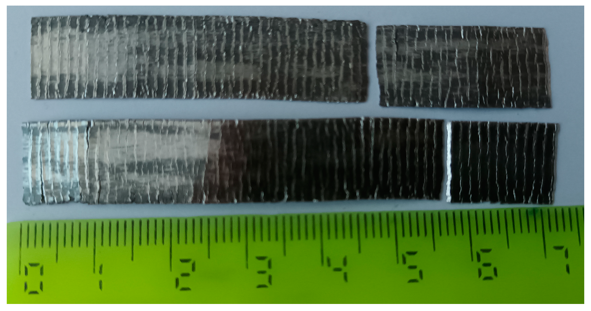
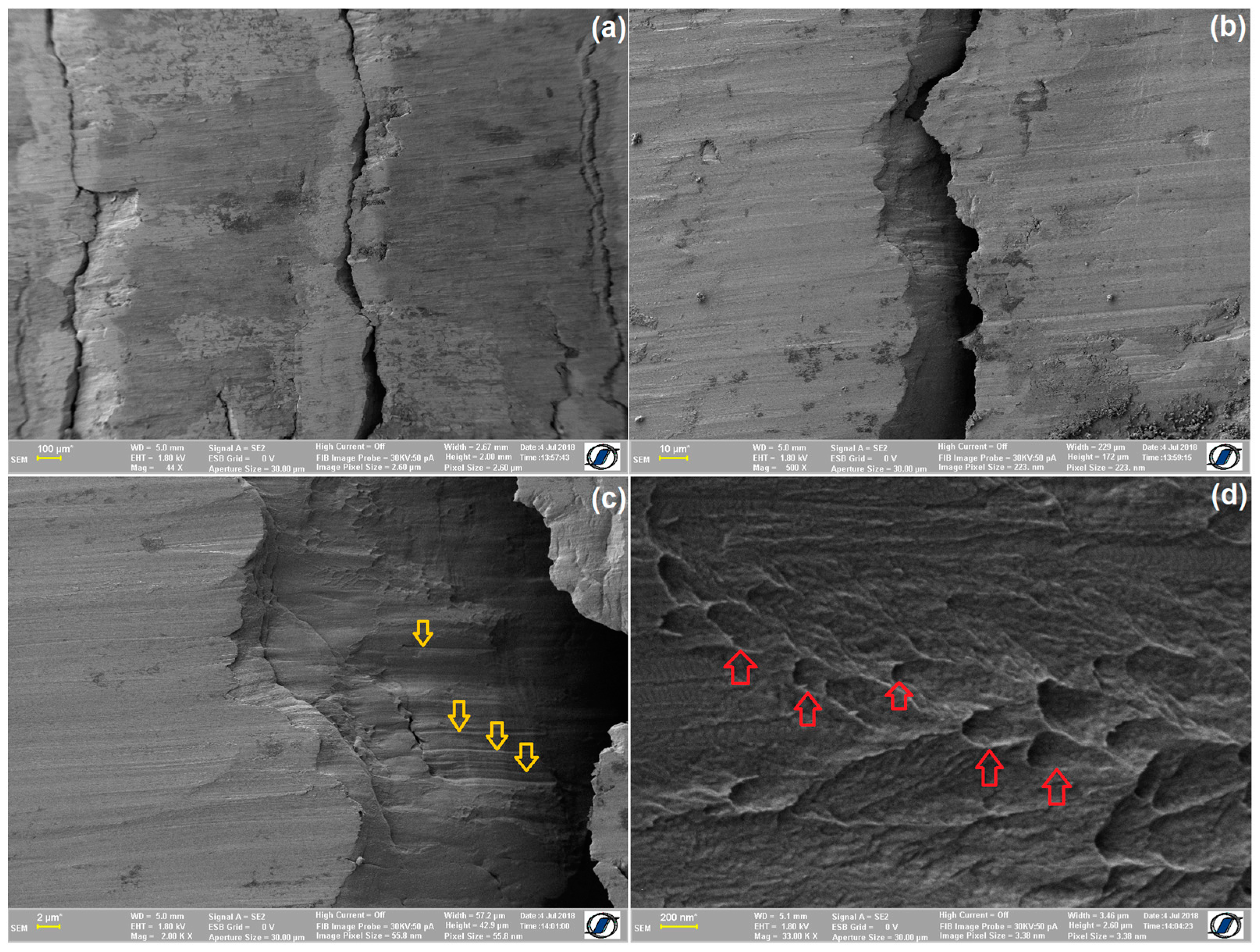
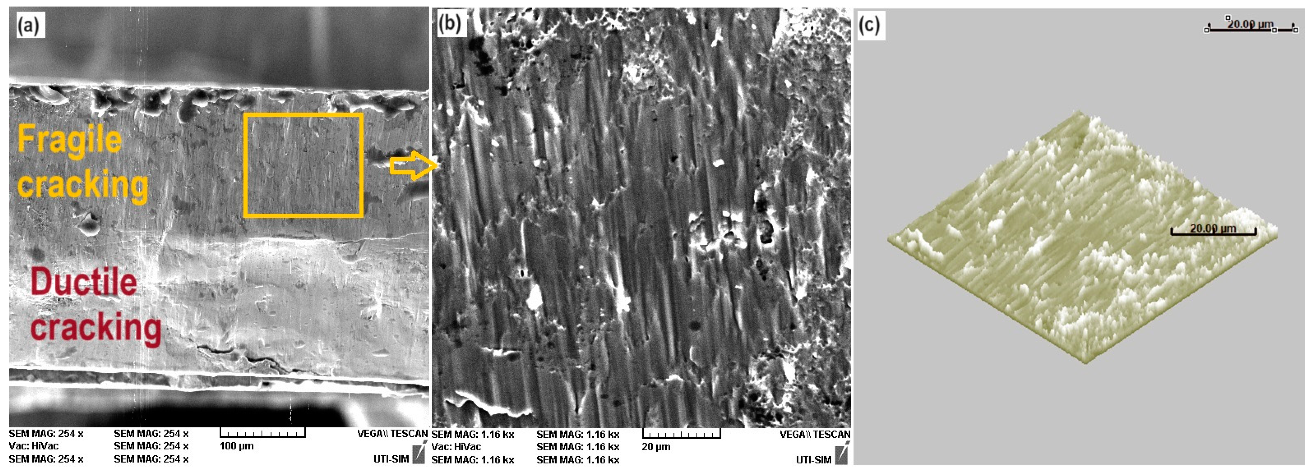
3. Results and Discussion

The structural analysis of hot-rolled Fe–28Mn–6Si–5Cr SMA specimens was firstly performed using XRD. The representative XRD pattern is displayed in Figure 3.
It is noticeable that there are three crystallographic variants of α′-bcc martensite plates, two of ε-hcp martensite and retained γ-fcc austenite.
Using semi-quantitative analysis, performed by comparing the heights of XRD maxima [47], the amounts of the three phases were determined as 56% α′-bcc, 26% γ-fcc and 18% ε-hcp martensite.
The majority presence of α′-bcc martensite plates has been confirmed using the representative SEM micrograph shown in Figure 4.
The difference between the area with the ε-hcp martensite plates and that with α′-bcc martensite plates is obvious. The former are very narrow and shallow while the latter are wide and deep, being characterized by a marked surface relief [48]. The presence of the bcc phase subdivides the matrix into domains of parallel ε-hcp martensite plates, which contributes to the enhancement of ε-hcp → γ-fcc reverse-martensitic transformation, which is desirable for its high-shape-recovery properties. [49]. On the other hand, it has been reported that the higher the content of the bcc phase, the higher the fracture strength, yield strength and hardness of the alloy [50]. Zhang et al. observed that α′-bcc-martensite was formed through the lattice expansion of fcc and hcp structures [51] while Mohri et al. assigned the formation of α′-bcc-martensite to the fast-cooling rate during the manufacturing process [52].
These characteristics are accommodation effects of the two martensite plate-types within the crystalline lattice of the matrix of γ-fcc austenite. ε-hcp martensite is produced by a simple atomic shuffle that causes a stacking fault, while keeping the close-packed plane families <111> γ // <001> ε [53]. α′-bcc martensite does not have any close-packed plane families, is hard and requires a marked distortion of the fcc matrix [54]. In addition, some of the present authors have previously reported that, in the structure of Fe–Mn–Si-based SMAs with large amounts of thermally induced α′-bcc martensite, multiple sub-bands may form, especially in the areas of multiple parallel α′-bcc plates [55]. These plates may be a cause for the high cracking sensitivity of these SMAs. In order to decrease the amount of α′-bcc martensite, the simplest method would be the reduction of the deformation degree [22].
After the first cold-rolling pass, some superficial cracks became visible, but after the second pass, the specimen cracked along its entire width. The resulting structures are visible in Figure 5.
It is obvious that, with the increase in cumulated thickness-reduction degree, cracking depth increased, but the average crack’s spacing, estimated at 1.3 mm, did not change.
A 0.6 mm thick specimen that partially cracked during the first cold-rolling pass was analyzed with increasing magnifications using HR-SEM. The representative micrographs are summarized in Figure 6.
According to Figure 6a, the width of the cracks does not exceed 0.1 mm. The cracks’ walls present obvious slip marks in Figure 6b, which were marked by descending arrows in the detail in Figure 6c. The HR-SEM micrograph from Figure 6d shows an array of dimples, some of them designated with ascending arrows. These dimples of ductile separation [56] indicate that the cracks that form during the first cold-rolling pass, characterized by a thickness-reduction degree of 25%, are an effect of ductile failure.
Nevertheless, in the second cold-rolling pass, even if the additional thickness-reduction degree is only a little higher; 33%, cracks deepening occurred by fragile facture because the deformed material has been work-hardened by cold rolling [57]. The fragile character of cracking is noticeable in Figure 7 on the fractured surface of a broken segment located between two cracks.
Figure 7a is a fractographic image of the lateral area of the broken fragment. Along the cross-section thickness, which can be approximated at 0.4 mm, two different areas are noticeable: a smooth and a rough area. The former was caused by ductile cracking during the first cold-rolling pass, with a 25% thickness-reduction degree. The latter was produced by fragile cracking, during the second cold-rolling pass, with an additional 33% thickness-reduction degree. Figure 7b illustrates a detail of the rough area, where parallel columns are visible. These aligned columns have a surface relief as well, as shown in the 3D image produced with the SEM-device software (VEGA II LSH TESCAN device).
The above argument can be an explanation for cracking occurrence during the cold rolling of hot-rolled and normalized Fe-28Mn-6Si-5Cr SMA lamellae. But it still does not account for the equal spacing of the cracks.
The general principle scheme of rolling is illustrated in Figure 8.
In zone I, there is a difference in the displacement speeds of specimen’s outer layer and cylinder’s surface. The outer layer, which is in contact with the rolling cylinder, is displaced with the entrance speed, Vi, which is lower than the tangential speed of the cylinder, Vc. Since Vc > Vi, it means that the specimen’s surface is moving slower than the roller’s surface; therefore, this area is designated as the delay zone, where the outer layer is elongated.
In zone II, the specimen’s outer layer becomes accelerated by the displacement of the feeding material. Therefore, the exit speed of the outer layer exceeds the tangential speed of the cylinder, Ve > Vc, and the respective area is designated as the advancement zone, where the outer layer is compressed.
In other words, within the delay zone, friction forces act in the same sense as the rolling forces, while in the advancement zone they act in opposite senses.
Between the delay and the advancement zones, there is a point, N (defined by the angle γ), where the two speeds are equal, Vi = Vc = Ve; therefore, it is called neutral point, and the respective area is called the adherence zone. It is only within this narrow zone, located around the angle γ, that the deformed material moves concomitantly with the roller.
It follows that any material volume that is continuously drawn into the driving zone (defined by the driving angle α) is subjected to an extension–compression cycle [58].
Considering the first cold-rolling pass, the cylinder’s radius is R = 0.018 m, the specimen’s initial thickness is h0 = 0.001 m, the final one is h = 0.0006 m, and the driving angle results in α ≈ 8.54°. The axial length of the driving area is R sinα ≈ 0.00267 m, which is double the average crack spacing, 1.3 mm.
Tensile failure tests, performed on dog-bone specimens cut from hot-rolled Fe–28Mn–6Si–5Cr SMA gave ultimate strains between 54.5% and 80.9%, as well as ultimate stresses between 950 MPa and 1035 Mpa. The former results were obtained on specimens with calibrated gauges with a cross-section of 4 mm2 and a length of 20 mm, while the latter were obtained on specimens with a cross-section of 2 mm2 and a length of 3 mm. These differences were ascribed to the decrease in the degree of intergranular incompatibility, which enabled easier stress propagation among neighboring grains in smaller cross-sections [59].
On the other hand, it has been reported that Fe–Mn–Si-based SMAs, subjected to tension–compression cycles, experience a deformation-induced reverse transformation, with martensite plates transforming from being tensile stress-induced to compression stress-induced and backwards [60].
One can assume that, during an extension–compression cycle caused by cold rolling, the deformed material drawn in the axial-driving area is broken in the neutral point, N, situated about the middle of the 2.7 mm length. In this way, the resulting cracks are evenly spaced at about 1.3 mm.

4. Summary and Conclusions

Ingots of Fe–28Mn–6Si–5Cr SMA, cast by levitation-induction melting and cut by spark erosion, were hot rolled at 1050 °C until they reached a final 1 mm thickness and normalized at 900 °C/1 h/air.
In this normalized state, besides an amount of ε-hcp martensite estimated at 13% and 26% parent γ-fcc austenite, several crystallographic variants of brittle α′-bcc martensite plates were observed using XRD and SEM, which could be the cause of cracking during further cold working.
Further thickness reductions were performed by cold rolling, first with a 25% and then with a 33% thickness-reduction degree.
After the first cold-rolling pass, evenly spaced incomplete cracks were observed with the walls characterized by ductile separation dimples. This ductile behavior could be related to the presence of γ-fcc austenite that enhanced plastic deformation, as illustrated by the representative HRSEM micrographs from Figure 6.
After the second cold-rolling pass, applied to the work-hardened material, the depth of the evenly spaced cracks increased until they crossed the entire specimen’s thickness. The cracks had rough separation-wall characteristic of fragile failure. But even in this case, due to the ductile character of γ-fcc austenite which occupied about 26% of the microstructure, the 0.4 mm thick cold-rolled specimens did not completely fail.
Due to the extension–compression cycle, caused by cold rolling, the material drawn into the drive area was continuously fractured when reaching the neutral point. The position of the neutral point was estimated at about half of the axial-driving area, which was calculated at 2.67 mm. This could explain crack formation with an average spacing of 1.3 mm.
These preliminary results have been intended to report the occurrence of these uncommon cold-rolling faults by suggesting some possible explanations for the two-stage cracking occurrence and the relatively evenly spaced cracks. In order to fully explain these two phenomena, observed during the cold rolling of hot-rolled normalized Fe–28Mn–6Si–5Cr SMAs, further investigations are necessary.
More intricate structural analyses (e.g., using XRD), focusing on the cracking points that occurred after various deformation degrees, are necessary to monitor the structural phase evolution during cold rolling.

Author Contributions

Conceptualization, L.-G.B.; methodology, G.B.; software, M.P.; validation, G.B., N.C., B.P. and L.-G.B.; formal analysis, M.P.; investigation, G.S., R.-I.C. and N.C.; resources, G.S.; data curation, B.P.; writing—original draft preparation, L.-G.B.; writing—review and editing, B.P.; visualization, R.-I.C.; supervision, G.B.; project administration, A.-M.R.; funding acquisition, A.-M.R. All authors have read and agreed to the published version of the manuscript.

Funding

This research received no external funding.

Data Availability Statement

Data are contained within the article.

Acknowledgments

The authors acknowledge the support of B. Istrate in performing XRD experiments.

Conflicts of Interest

The authors declare no conflicts of interest.

References

  1. Yang, Y.; Bahador, S.D.; Lihua, T.; Lei, Z. Strain transfer models for macrofiber-composite strain actuators. Mater. Manuf. Proc. 2010, 25, 237–242. [Google Scholar] [CrossRef]
  2. Sun, L.; Huang, W.M.; Ding, Z.; Zhao, Y.; Wang, C.C.; Purnawali, H.; Tang, C. Stimulus-responsive shape memory materials: A review. Mater. Design 2012, 33, 577–640. [Google Scholar] [CrossRef]
  3. Ma, J.; Karaman, I. Expanding the repertoire of shape memory alloys. Science 2010, 327, 1468–1469. [Google Scholar] [CrossRef] [PubMed]
  4. Kamila, S. Introduction, classification and applications of smart materials: An overview. Am. J. Appl. Sci. 2013, 10, 876–880. [Google Scholar] [CrossRef]
  5. Wayman, C.M.; Duerig, T.W. An introduction to martensite and shape memory. In Engineering Aspects of Shape Memory Alloys; Duerig, T.W., Melton, K.N., Stöckel, D., Wayman, C.M., Eds.; Butterworth-Heinemann: London, UK, 1990; pp. 3–20. [Google Scholar]
  6. Otsuka, K.; Wayman, C.M. Introduction. In Shape Memory Materials; Otsuka, K., Wayman, C.M., Eds.; Cambridge University Press: Cambridge, UK, 1998; pp. 1–26. [Google Scholar]
  7. Kumar, P.K.; Lagoudas, D.C. Introduction to Shape Memory Alloys. In Shape Memory Alloys. Modelling and Engineering Applications; Lagoudas, D.C., Ed.; Springer: Berlin/Heidelberg, Germany, 2008; pp. 1–51. [Google Scholar]
  8. Oliveira, J.P.; Zeng, Z.; Berveiller, S.; Bouscaud, D.; Fernandes, F.B.; Miranda, R.M.; Zhou, N. Laser Welding of Cu-Al-Be Shape Memory Alloys: Microstructure and Mechanical Properties. Mater. Design 2018, 148, 145–152. [Google Scholar] [CrossRef]
  9. Gao, Z.Y.; Yang, S.; Zhang, H.J.; Dong, G.F.; Cai, W. Effect of aging on phase transformation, thermoelastic and fracture behaviour of Mn53Ni25Ga22 ferromagnetic shape memory alloy. Mat. Sci. Eng. A 2014, 594, 1–6. [Google Scholar] [CrossRef]
  10. Saedi, S.; Acar, E.; Raji, H.; Saghaian, S.E.; Mirsayar, M. Energy damping in shape memory alloys: A review. J. Alloys Compd. 2023, 956, 170286. [Google Scholar] [CrossRef]
  11. Amadi, A.; Mohyaldinn, M.; Ridha, S.; Ola, V. Advancing engineering frontiers with NiTi shape memory alloys: A multifaceted review of properties, fabrication, and application potentials. J. Alloys Compd. 2024, 976, 173227. [Google Scholar] [CrossRef]
  12. Mehta, K.; Gupta, K. Fabrication and Processing of Shape Memory Alloys; Springer: Berlin/Heidelberg, Germany, 2019; pp. 9–37. [Google Scholar] [CrossRef]
  13. Dasgupta, R. A look into Cu-based shape memory alloys: Present scenario and future prospects. J. Mater. Res. 2014, 29, 1681–1698. [Google Scholar] [CrossRef]
  14. James, R.D.; Hane, K.F. Martensitic transformations and shape-memory materials. Acta Mater. 2000, 48, 197–222. [Google Scholar] [CrossRef]
  15. Murakami, M.; Otsuka, H.; Suzuki, H.G.; Matsuda, S. Complete shape memory effect in polycrystalline Fe-Mn-Si alloys. In Proceedings of the International Conference on Martensitic Transformation (Japan Institute of Metals), Nara, Japan, 26–30 August 1986; pp. 985–990. [Google Scholar]
  16. Dunne, D. Diffusionless transformations, high strength steels, modelling and advanced analytical techniques. In Phase Transformations in Steels; Pereloma, E., Edmonds, D.V., Eds.; Woodhead: Cambridge, MA, USA, 2012; Volume 2, pp. 83–125. [Google Scholar]
  17. Tanaka, Y.; Himuro, Y.; Kainuma, R.; Sutou, Y.; Omori, T.; Ishida, K. Ferrous Polycrystalline Shape-Memory Alloy Showing Huge Superelasticity. Science 2010, 327, 1488–1490. [Google Scholar] [CrossRef] [PubMed]
  18. Omori, T.; Ando, K.; Okano, M.; Xu, X.; Tanaka, Y.; Ohnuma, I.; Kainuma, R.; Ishida, K. Superelastic Effect in Polycrystalline Ferrous Alloys. Science 2011, 333, 68–71. [Google Scholar] [CrossRef]
  19. Shimpo, Y.; Seki, H.; Wongsatanawarid, A.; Taniguchi, S.; Maruyama, T.; Kurita, T.; Murakami, M. The improvement of the superconducting Y–Ba–Cu–O magnet characteristics through shape recovery strain of Fe–Mn–Si alloys. Phys. C 2010, 470, 1170–1172. [Google Scholar] [CrossRef]
  20. Kajiwara, S. Characteristic features of shape memory effect and related transformation behavior in Fe-based alloys. Mater. Sci. Eng. A 1999, 273–275, 67–88. [Google Scholar] [CrossRef]
  21. Bracke, L.; Mertens, G.; Penning, J.; De Cooman, B.C.; Liebeherr, M.; Akdut, N. Influence of phase transformations on the mechanical properties of high-strength austenitic Fe-Mn-Cr steel. Metall. Mater. Trans. A 2006, 37A, 307–317. [Google Scholar] [CrossRef]
  22. Arruda, G.J.; Buono, V.T.L.; Andrade, M.S. The influence of deformation on the microstructure and transformation temperatures of Fe–Mn–Si–Cr–Ni shape memory alloys. Mater. Sci. Eng. A 1999, 273–275, 528–532. [Google Scholar] [CrossRef]
  23. Li, J.C.; Zhao, M.; Jiang, Q. Alloy design of Fe-Mn-Si-Cr-Ni shape memory alloys related to stacking-fault energy. Metall. Mater. Trans. A 2000, 31, 581–584. [Google Scholar] [CrossRef]
  24. Sato, A.; Chishima, E.; Soma, K.; Mori, T. Shape memory effect in γ ↔ ε transformation in Fe-30Mn-1Si alloy single crystals. Acta Metall. 1982, 30, 1177–1183. [Google Scholar] [CrossRef]
  25. Murakami, M.; Otsuka, H.; Suzuki, H.; Matsuda, S. Effect of alloying content, phase and magnetic transformation on shape memory effect of Fe-Mn-Si alloys. Trans. Iron Steel Inst. Jpn. 1987, 27, B88. [Google Scholar]
  26. Otsuka, H.; Yamada, H.; Maruyama, T.; Tanahashi, H.; Matsuda, S.; Murakami, M. Effects of alloying additions on Fe-Mn-Si shape memory alloys. ISIJ Int. 1990, 30, 675–679. [Google Scholar] [CrossRef]
  27. Moriya, Y.; Kimura, H.; Ishizaki, S.; Hashizume, S.; Suzuki, S.; Suzuki, H.; Sampei, T. Properties of Fe-Cr-Ni-Mn-Si (-Co) shape memory alloys. J. Phys. IV C 1991, 4, 433–437. [Google Scholar] [CrossRef]
  28. Berns, H.; Theisen, W. Ferrous Materials: Steel and Cast Iron; Springer: Berlin/Heidelberg, Germany, 2008; pp. 26–30. [Google Scholar] [CrossRef]
  29. Manjaiah, M.; Narendranath, S.; Basavarajappa, S. Review on non-conventional machining of shape memory alloys. Trans. Nonferrous Met. Soc. China 2014, 24, 12–21. [Google Scholar] [CrossRef]
  30. Kubo, H.; Otsuka, H.; Farjami, S.; Maruyama, T. Characteristics of Fe–Mn–Si–Cr shape memory alloys in centrifugal casting. Scr. Mater. 2006, 55, 1059–1062. [Google Scholar] [CrossRef]
  31. Druker, A.V.; Sobrero, C.; Malarría, J.; Garbe, U.; Brokmeier, H.-G.; Bolmaro, R.E. Effect of texture heterogeneities on the shape memory properties of rolled Fe-Mn-Si SMA. Z. Kristallogr Suppl. 2009, 30, 297–302. [Google Scholar] [CrossRef]
  32. Ginzburg, V.B. Steel-Rolling Technology: Theory and Practice; Marcel Dekker Inc.: New York, NY, USA, 1989; pp. 187–198. [Google Scholar]
  33. Zhi, Y.; Wang, X.; Wang, S.; Liu, X. A review on the rolling technology of shape flat products. Int. J. Adv. Manuf. Technol. 2018, 94, 4507–4518. [Google Scholar] [CrossRef]
  34. Lee, C. Stresses and Defects in Roll Products: A Review of Stress Models and Control Techniques. Int. J. Precis. Eng. Manuf. 2018, 19, 781–789. [Google Scholar] [CrossRef]
  35. Zhao, R.-J.; Fu, J.-X.; Wu, Y.-X.; Yang, Y.-J.; Zhu, Y.-Y.; Zhang, M. Representative Technologies for Hot Charging and Direct Rolling in Global Steel Industry. ISIJ Int. 2015, 55, 1816–1821. [Google Scholar] [CrossRef]
  36. Wang, D.-C.; Liu, H.-M.; Liu, J. Research and Development Trend of Shape Control for Cold Rolling Strip. Chin. J. Mech. Eng. 2017, 30, 1248–1261. [Google Scholar] [CrossRef]
  37. Li, L.; Ding, S.X. Optimal Detection Schemes for Multiplicative Faults in Uncertain Systems With Application to Rolling Mill Processes. IEEE Trans. Control Syst. Technol. 2020, 28, 2432–2444. [Google Scholar] [CrossRef]
  38. Yang, Y.; Zhan, D.; Qiu, G.; Li, X.; Jiang, Z.; Zhang, H. Inclusion evolution in solid steel during rolling deformation: A review. J. Mater. Res. Technol. 2022, 18, 5103–5115. [Google Scholar] [CrossRef]
  39. Elsilä, U.; Röning, J. Defect prediction in hot strip rolling. Ironmak. Steelmak. 2004, 31, 241–248. [Google Scholar] [CrossRef]
  40. Ma, H.; Chen, C.; Qi, X.; Li, J.; Lv, B.; Zhang, F. Effect of rolling temperature on microstructure evolution and mechanical properties of high carbon high manganese steel. J. Mater. Res. Technol. 2022, 21, 319–329. [Google Scholar] [CrossRef]
  41. Muley, A.; Mundlik, A.; Nairale, S. Defects in rolled sheets-A paper review. Int. Res. J. Eng. Technol. 2022, 9, 248–252. [Google Scholar]
  42. Suru, M.-G.; Lohan, N.M.; Pricop, B.; Spiridon, I.P.; Mihalache, E.; Comăneci, R.I.; Bujoreanu, L.-G. Structural effects of high-temperature plastic deformation process on martensite plate morphology in a Fe-Mn-Si-Cr SMA. Int. J. Mater. Prod. Technol. 2015, 50, 276–288. [Google Scholar] [CrossRef]
  43. Popa, M.; Popa, F.; Pricop, B.; Cimpoeșu, N.; Lohan, N.-M.; Kicsi, G.; Istrate, B.; Bujoreanu, L.-G. Heat Treatment and Dynamic Mechanical Analysis Strain Sweep Effects on the Phase Structure and Morphology of an Fe-28Mn-6Si-5Cr Shape Memory Alloy. Nanomaterials 2023, 13, 1250. [Google Scholar] [CrossRef] [PubMed]
  44. Spiridon, I.-P.; Lohan, N.-M.; Suru, M.-G.; Mihalache, E.; Bujoreanu, L.-G.; Pricop, B. A study of free recovery in a Fe–Mn–Si–Cr shape memory alloy. Met. Sci. Heat. Treat. 2016, 57, 548–552. [Google Scholar] [CrossRef]
  45. Paleu, V.; Gurău, G.; Comăneci, R.I.; Sampath, V.; Gurău, C.; Bujoreanu, L.G. A new application of Fe-28Mn-6Si-5Cr (mass%) shape memory alloy, for self adjustable axial preloading of ball bearings. Smart Mater. Struct. 2018, 27, 75026. [Google Scholar] [CrossRef]
  46. Pricop, B.; Söyler, A.U.; Özkal, B.; Bujoreanu, L.-G. Powder Metallurgy: An Alternative for FeMnSiCrNi Shape Memory Alloys Processing. Front. Mater. 2020, 7, 247. [Google Scholar] [CrossRef]
  47. Sawaguchi, T.; Bujoreanu, L.-G.; Kikuchi, T.; Ogawa, K.; Yin, F. Effects of Nb and C in Solution and in NbC Form on the Transformation-related Internal Friction of Fe–17Mn (mass%) Alloys. ISIJ Int. 2008, 48, 99–106. [Google Scholar] [CrossRef]
  48. Wen, Y.H.; Peng, H.B.; Sun, P.P.; Liu, G.; Li, N. A novel training-free cast Fe–18Mn–5.5Si–9.5Cr–4Ni shape memory alloy with lathy delta ferrite. Scr. Mater. 2010, 62, 55–58. [Google Scholar] [CrossRef]
  49. Kim, D.; Ferretto, I.; Leinenbach, C.; Lee, W.; Kim, W. Effect of direct aging on microstructure, mechanical properties and shape memory behavior of Fe-17Mn-5Si-10Cr-4Ni-(V, C) shape memory alloy fabricated by laser powder bed fusion. Mater. Char 2023, 197, 112705. [Google Scholar] [CrossRef]
  50. Zou, Q.; Ye, X.; Li, Y.; Luo, W.; Luo, Y. Preparation and properties of Fe–Mn–Si–Cr–Ni shape memory alloy. J. Mater. Sci. 2023, 58, 3346–3359. [Google Scholar] [CrossRef]
  51. Zhang, Z.-X.; Zhang, J.; Wu, H.; Ji, Y.; Kumar, D.D. Iron-Based Shape Memory Alloys in Construction: Research, Applications and Opportunities. Materials 2022, 15, 1723. [Google Scholar] [CrossRef]
  52. Mohri, M.; Ferretto, I.; Khodaverdi, H.; Leinenbach, C.; Ghafoori, E. Influence of thermomechanical treatment on the shape memory effect and pseudoelasticity behavior of conventional and additive manufactured FeeMneSieCreNi-(V,C) shape memory alloys. J. Mater. Res. Technol. 2023, 24, 5922–5933. [Google Scholar] [CrossRef]
  53. Sawaguchi, T.; Tomota, Y.; Yoshinaka, F.; Harjo, S. Evidence supporting reversible martensitic transformation under cyclic loading on Fe–Mn–Si–Al alloys using in situ neutron diffraction. Acta Mater. 2023, 242, 118494. [Google Scholar] [CrossRef]
  54. Singh, D.; Tasaki, W.; Yoshinaka, F.; Takamori, S.; Emura, S.; Tsuchiya, K.; Sawaguchi, T. Unveiling the transformation pathways of hierarchical γ90–εtwin–α′ triple phase structure formation at ε-ε martensite intersection. Mater. Charact. 2023, 205, 113358. [Google Scholar] [CrossRef]
  55. Pricop, B.; Grigoras, M.; Borza, F.; Özkal, B.; Bujoreanu, L.-G. On the Possible Cause of Sudden Storage Modulus Increase during the Heating of PM FeMnSiCrNi SMAs. Nanomaterials 2022, 12, 2342. [Google Scholar] [CrossRef] [PubMed]
  56. Maruschak, P.; Konovalenko, I.; Sorochak, A. Methods for evaluating fracture patterns of polycrystalline materials based on the parameter analysis of ductile separation dimples: A review. Eng. Fail. Anal. 2023, 153, 107587. [Google Scholar] [CrossRef]
  57. Bulzak, T.; Pater, Z.; Tomczak, J.; Wojcik, L.; Murillo-Marrodan, A. Internal crack formation in cross wedge rolling: Fundamentals and rolling methods. J. Mater. Proc. Technol. 2022, 307, 117681. [Google Scholar] [CrossRef]
  58. Wusatowski, Z. Fundamentals of Rolling; Pergament Press: Oxford, UK, 1969; pp. 69–202. [Google Scholar]
  59. Mocanu, M.; Mihalache, E.; Comăneci, R.-I.; Pricop, B.; Özkal, B.; Bujoreanu, L.-G. Tensile Stress-Induced Structural Changes Associated with Martensite Transformations in Fe-Mn-Si Based Shape Memory Alloys. Mater. Sci. Forum 2017, 907, 25–30. [Google Scholar] [CrossRef]
  60. Sawaguchi, T.; Bujoreanu, L.-G.; Kikuchi, T.; Ogawa, K.; Koyama, M.; Murakami, M. Mechanism of reversible transformation-induced plasticity of Fe–Mn–Si shape memory alloys. Scr. Mater. 2008, 59, 826–829. [Google Scholar] [CrossRef]
Figure 1. Rolling cracks: (a) three types of schematic cracks [41]; (b) bilateral edge cracks on an overheated Fe–Mn–Si specimen; (c) uneven edge cracks on a curved hot-rolled Fe–Mn–Si-Cr-Ni specimen; (d) common edge cracks on a hot-rolled Fe–Mn–Si-Cr-Ni specimen.
Crystals 14 00250 g001
Figure 2. Evenly spaced cracks on the surface of hot-rolled and normalized specimens after a total 58% thickness reduction in two cold-rolling passes.
Crystals 14 00250 g002
Figure 3. XRD pattern of a hot-rolled normalized Fe–28Mn–6Si–5Cr SMA specimen.
Crystals 14 00250 g003
Figure 4. Typical SEM micrograph of a hot-rolled normalized Fe-28Mn-6Si-5Cr SMA specimen.
Crystals 14 00250 g004
Figure 5. Macrographs of cold-rolled specimens reveal shallow cracks after a 25% thickness-reduction degree (up) and deep cracks after an additional 33% thickness-reduction degree (down).
Crystals 14 00250 g005
Figure 6. SEM micrographs revealing the fractographic images of the superficial cracks caused by the first cold-rolling pass applied to a hot-rolled normalized Fe–28Mn–6Si–5Cr SMA specimen: (a) general aspect of three cracks; (b) detail of a single crack; (c) magnified fractography of one crack with slip marks highlighted with yellow arrows; (d) HR-SEM fractography illustrating the ductile character of cracking, with an array of dimples marked with red arrows.
Crystals 14 00250 g006
Figure 7. SEM micrographs revealing the fragile character of the cracking produced during the second cold-rolling pass: (a) failure surface of the broken fragment, emphasizing two types of cracking; (b) detail of the columnar area of fragile cracking; (c) 3D image of SEM micrograph.
Crystals 14 00250 g007
Figure 8. Principle scheme of rolling.
Crystals 14 00250 g008
Table 1. Crystallographic data of XRD maxima corresponding to the metallographic phases of Fe–Mn–Si-based SMAs.
2θ, °I (a.u.)Miller IndicesPhase
hkl
41.166 268 1 0 0 ε (hcp)
43.608 999 1 1 1 γ (fcc)
44.381 274 0 0 2 ε (hcp)
44.485 100 1 1 0 α′ (bcc)
47.041 999 1 0 1 ε (hcp)
50.795 420 2 0 0 γ (fcc)
62.128 112 1 0 2 ε (hcp)
64.779 20 2 0 0 α′ (bcc)
74.681 172 2 2 0 γ (fcc)
75.025 100 1 1 0 ε (hcp)
81.986 50 2 1 1 α′ (bcc)
83.634 98 1 0 3 ε (hcp)
89.358 13 2 0 0 ε (hcp)
90.673 158 3 1 1 γ (fcc)
91.541 94 1 1 2 ε (hcp)
93.446 65 2 0 1 ε (hcp)
95.953 43 2 2 2 γ (fcc)
98.117 12 0 0 4 ε (hcp)
98.475 18 2 2 0 α′ (bcc)
Disclaimer/Publisher’s Note: The statements, opinions and data contained in all publications are solely those of the individual author(s) and contributor(s) and not of MDPI and/or the editor(s). MDPI and/or the editor(s) disclaim responsibility for any injury to people or property resulting from any ideas, methods, instructions or products referred to in the content.

