Article

Tribological Behavior and Wear Mechanism of Cu-SiO2 Sintered Composite under Different Sliding Speeds

1
School of Chemical and Environmental Engineering, Liaoning University of Technology, Jinzhou 121001, China
2
School of Materials Science and Engineering, Liaoning University of Technology, Jinzhou 121001, China
*
Author to whom correspondence should be addressed.
Crystals 2024, 14(3), 232; https://doi.org/10.3390/cryst14030232
Submission received: 24 January 2024 / Revised: 22 February 2024 / Accepted: 23 February 2024 / Published: 28 February 2024

Abstract

:
In this paper, the tribological behavior of Cu-SiO2 composite against 1045 steel was studied. Based on the characterization of worn surface, worn subsurface and wear debris in morphology and composition, the friction layer effects on the tribological behavior of coupled materials and the wear mechanism were discussed. Abrasive wear and adhesive wear are the dominant mechanisms at the 0.56 m/s–1.12 m/s condition. Delamination wear and oxidation wear are the dominant wear mechanisms at the 1.68 m/s–2.24 m/s condition. Plastic and thermal deformation cause the evolution in morphology and structure of the tribolayer of Cu-SiO2. There is a certain correlation between the friction coefficient and the variation in friction temperature during sliding wear of Cu-SiO2 and 1045 steels. The addition of SiO2 induces the accumulation of frictional heat at the friction interface, which leads to an increase in the average temperature of the contact surface and transfer.

1. Introduction

During friction and wear, the materials adjacent to the contact surface are modified. The modified materials are called the third body (TB), tribolayer (TL) and mechanically mixed layer (MML) [1,2]. The third body concept was introduced by Godet [3]. From then on, more and more studies concentrated on the effects of TB/TL/MML in friction and wear properties of materials. It has been widely recognized that TL has an important effect on friction and wear behavior of materials [4,5,6,7,8]. The morphology, composition and structure of TLs are different from the contact bulk materials. Rigney and Österle found that a nanocrystalline layer is presented underneath the worn surface. The factors which can affect TL have been widely investigated, such as load, environmental temperature and so on. M.H. Cho [6] found that the thickness of TLs is affected by the contact temperature of the frictional surface. The thick TLs on the disk surface tend to reduce the wear and oscillation amplitude of the friction coefficient. W. Österle Rigney [7] presented the TLs on copper. Depending on the constituent of the pad, one, two or three layers were identified. The three-layer structure comprised: (i) A 100 nm thick friction film containing nanocrystalline metal oxides and an amorphous phase which was enriched with sulfur, (ii) A nanocrystalline friction layer of compacted wear debris accommodating surface roughness, (iii) A severely deformed layer if the supporting constituent was a metal particle. Though the majority of loose wear particles were iron oxide, the friction film which adhered tightly to the pad surface contained a large amount of copper and sulfur, whereas zinc was transferred to the cast-iron rotor. A.R. Riahi [8] showed that mild wear in the graphitic composites is primarily controlled by formation of the TLs on the contact surfaces. When two coupled materials rub against each other, the work of frictional force will be consumed in plastically deforming at the contact surface and initiating some secondary processes (e.g., acoustic and luminescence emission, heat). It is known that friction heat soon generates under unlubricated sliding, especially at high speed, and induces the rise in bulk temperature. The plastic deformation and flow on the contact surface are improved. And then, the shear stress increases, resulting from the enlarged contact spot. The major portion of work will be transformed into thermal energy and generating frictional heat [9,10]. The accumulation of frictional heat can induce the formation of a temperature gradient near the contact surface [11,12]. The second recrystallization, phase transformation and element diffusion can also happen [13,14].
It is shown that friction heat has an important influence on the tribological behavior and failure of sliding components. The friction coefficient of most metals decreases with the rise in surface temperature. The wear can be aggravated due to the frictional heat. The friction heat modifies the frictional surface. But less attention has been paid to the effect of friction heat on the tribolayer and tribological behavior. Powder metallurgy (PM) Cu-based composites are used in aircraft and automobile brake systems. The composites consist of a combination of numerous ingredients. Hard particles, such as SiO2 or SiC, can improve the wear resistance. In our present work, we aim to explore the effect of frictional heat on the friction coefficient, wear rate and tribolayer of Cu-SiO2. We chose Cu-SiO2 composite as the study subject. The addition of hard particles (SiC, SiO2) into the copper matrix can improve the strength, and copper matrix (Cu-SiC, Cu-SiO2) composite can potentially be used as a brake material [15,16,17,18]. The wear mechanism, considering frictional heat, is discussed. Attempts to study the correlation between tribological behavior and TLs, considering frictional heating, are made. A new insight is provided for the tribological design of materials during unlubricated wear.

2. Materials and Methods
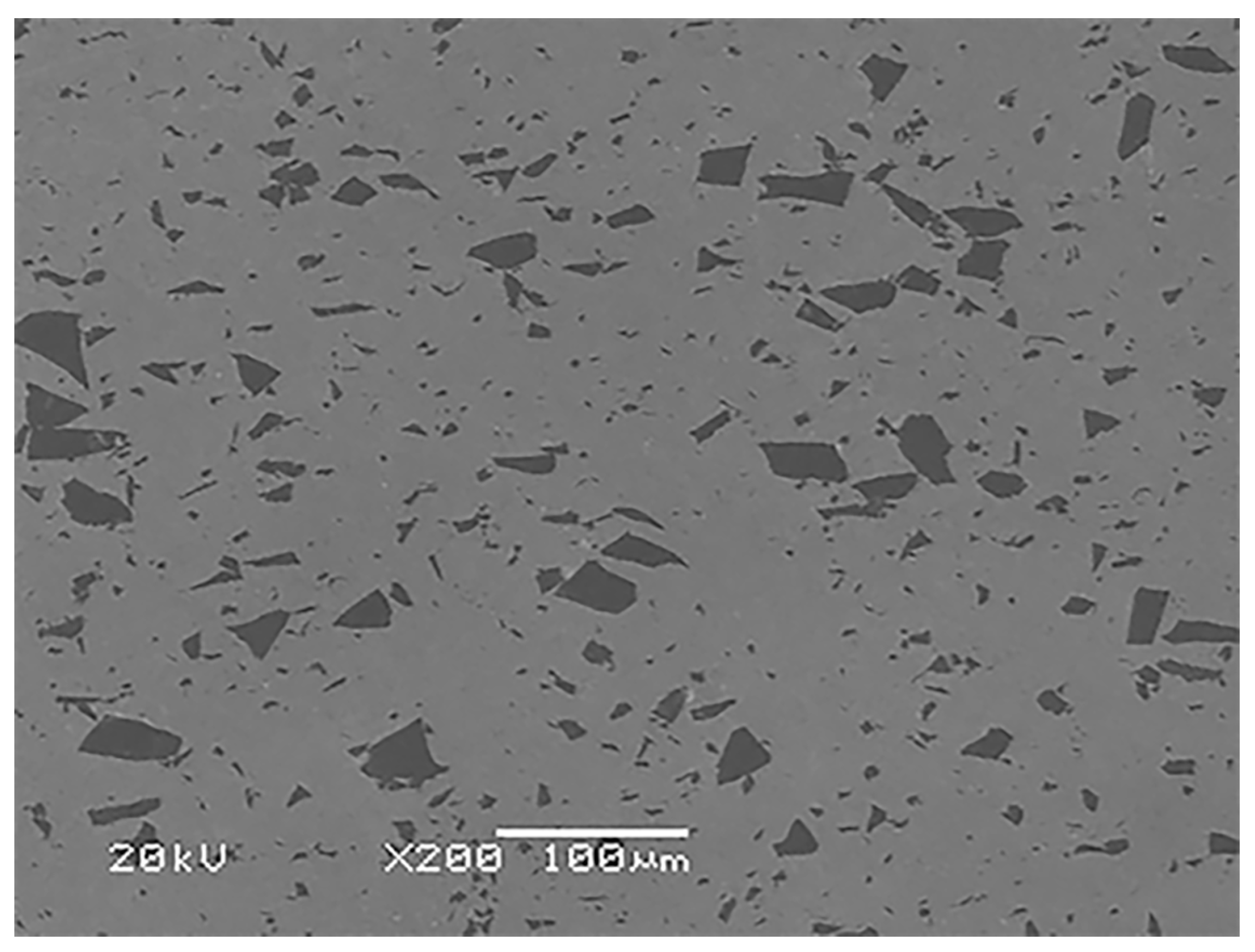
2.1. Materials

The raw material in the experiment is electrolytic copper powder; it is provided by Shanghai Shanpu Chemical Co., Ltd. (Shanghai, China) and the purity is greater than 99.6%. SiO2 powder is provided by Tianjin Meiyu Chemical Co., Ltd. (Tianjin, China), the purity is greater than 99.4% and the particle size distribution is from 5–30 µm. Two powders of Cu-5 wt% SiO2 were dry mixed in a ball mill for 12 h. The mixed powder, after ball milling, was cold pressed into cylindrical blocks at 230 MPa, and then hot pressed and sintered in a medium frequency induction furnace. The sintering temperature is 850 ° C, the holding time is 40 min and the sintering pressure is about 22 MPa. Finally, the Φ 25 mm × 20 mm cylindrical blocks. The relative density of Cu-SiO2 sintered body is 97%, and the Brinell hardness is around HB 73 (with a load of 62.5 kgf and a holding time of 30 s). The microstructure of sintered Cu-SiO2 is shown in Figure 1. The AISI 1045 steel (0.42~0.50% C, 0.17~0.37% Si, 0.50~0.80% Mn, 98.91~98.33% Fe) is chosen for the friction pair with a composite material because the steel is usually used in other works, and it is commercially available. The steel surface is HB 180 ± 3 in hardness.

2.2. Sliding Wear Tests

The sliding wear experiment was conducted on a self-made friction and wear test machine, using a one-way sliding method of pin disk contact. The scales sample is Cu-SiO2 with a diameter of 5 mm, and the contact end face is processed into a hemispherical shape. The surface is polished with metallographic sandpaper. The disk sample is 1045 steel that has undergone annealing treatment, with a size of Ф 50 mm × 8 mm. Before the experiment, clean the pin and disk samples with acetone ultrasound for 10 min, and dry them before use. The sliding experiments were conducted at room temperature and in an air atmosphere. The friction coefficient is automatically recorded in real-time by a computer. Use an electronic balance with an accuracy of 0.1 mg to weigh the mass of the pin sample before and after wear, using the formula Wr = Δ. Calculate the wear rate of the pin sample using m/(PL). Among them, Δ M represents quality loss; that is, the quality difference before and after wear; P represents contact pressure, L represents sliding distance. In order to measure the temperature of the substrate material during sliding wear, a hole was drilled at the end of the pin specimen 5 mm away from the contact surface, and a thermocouple was fixed in it. The temperature change during the sliding process was automatically recorded by connecting a multimeter. The sliding speed was 1.68 m/s–3.36 m/s. The test device is shown in the embedded small figure in Figure 2a.

2.3. Morphology and Composition Characterization

The worn samples are cleaned by ultrasound and then hot mounted. Use a precision linear cutting saw (Buehler ISO MET-1000, Buehler Inc., Salem, MA, USA) to cut the cross-section perpendicular to the worn surface, parallel to or perpendicular to the sliding direction in the area of wear marks or spots. The obtained cross-sectional samples were polished on an automatic polishing machine (Buehler ISO MET-1000, Buehler Inc., Salem, MA, USA) for observation. The worn surfaces of samples were observed using SEM (JSM-5600LV, JEOL Ltd., Tokyo, Japan). The chemical composition of the worn surfaces was analyzed by EDS, XPS and LRS.
After the wear tests, the chemical composition of the worn surfaces was analyzed by X-ray photoelectron spectroscopy (Thermo Fisher ESCALAB Xi+, Thermo Fisher Scientific, Waltham, MA, USA) and laser Raman spectroscopy (Invia Renishaw, Renishaw, Inc., Wotton-under-Edge, UK). A monochromatized Al K-radiation (1486.6 eV) was used as X-ray source and with a spot size of 250 nm. The energy scales were calibrated with Ag 3d5/2 and Cu 2p3/2 lines. The binding energies of the peaks were referenced to C 1s binding energy as 284.6 eV. Sputter depth profiles were obtained on the samples by a 3 keV Ar+ ion beam with a current density of 1.0 nA mm−2.

3. Results

3.1. Friction Coefficient, Wear Rate and Bulk Temperature

The friction coefficient (μ), wear rate (Wr) and bulk temperature (Tbr) of Cu-SiO2 in sliding against 1045 steel at 0.56 m/s–2.24 m/s are shown in Figure 2. The friction coefficients of Cu-SiO2 in sliding against 1045 steel at 0.56 m/s and 1.68 m/s are similar. However, the μ at 1.68 m/s fluctuates heavily. The Tbr and Wr of Cu-SiO2 composite in sliding against 1045 steel at 1.68 m/s are higher, especially the wear rate. The Wr of Cu-SiO2 composite at 1.68 m/s and 2.24 m/s is multiple.

3.2. Morphology of Cu-SiO2 Worn Surface

Two different morphologies are shown in Figure 3 and Figure 4 on the worn surfaces of Cu-SiO2 at 0.56 m/s and 1.68 m/s. The morphologies of low magnification at the two sliding speeds are similar, as shown in Figure 3a and Figure 4a. The worn surfaces are characterized by two distinct regions, the dense layer (the black region) and the loose particle layer (the white region). At 0.56 m/s, the dense layer is smooth, and the fracture is propagated in Figure 3b, while at 1.68 m/s, the plastic flow is evident and the voids resulting from pull-out of the SiO2 particles can be seen. Comparing Figure 3c and Figure 4c, more exposed SiO2 particles can be seen.

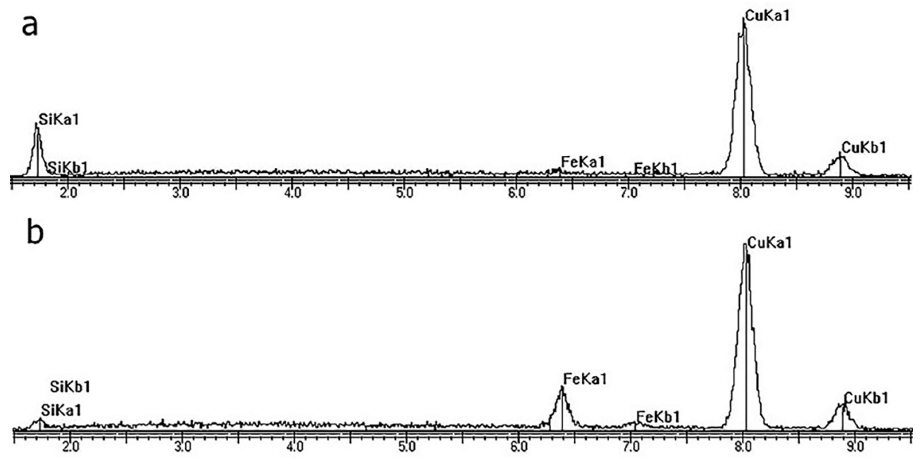
3.3. Composition of Cu-SiO2 Worn Spot

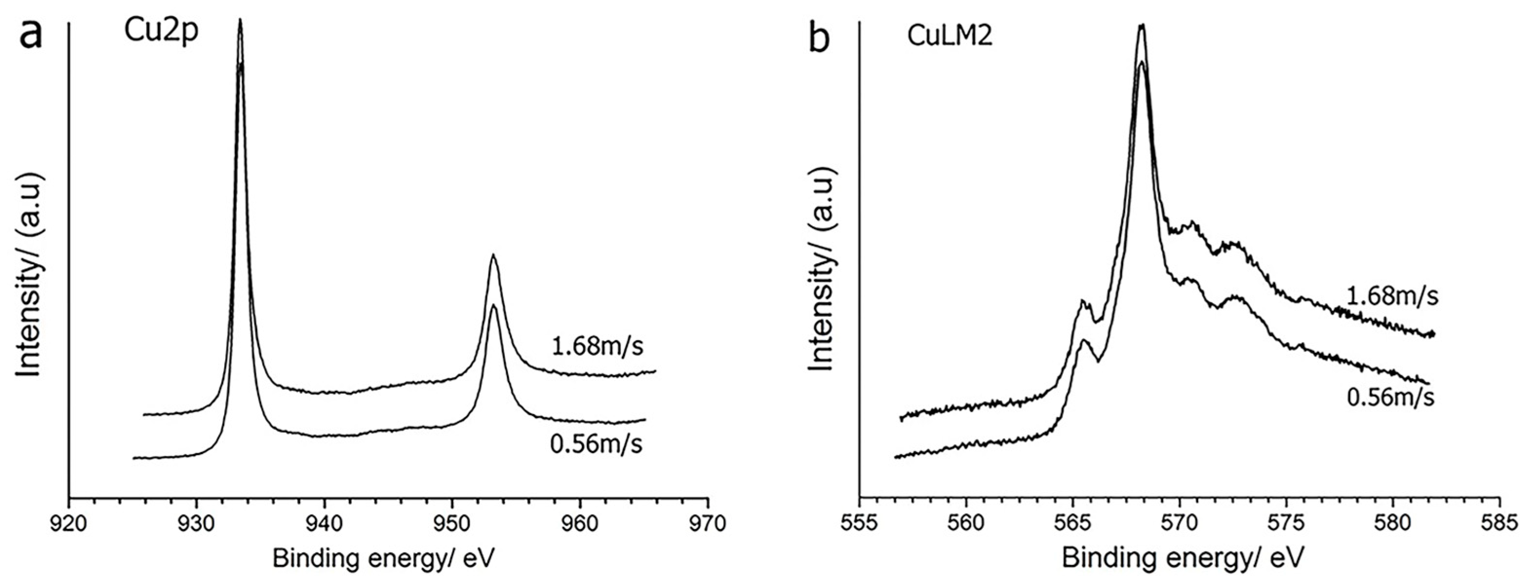
3.3.1. XPS of Cu-SiO2 Worn Spot

To further know the chemical states of the copper element, XPS analysis was conducted (Figure 5). It can be seen that the binding energy of Cu 2p is about 932.7 eV, responding to Cu + 1 or Cu0, since Cu + 1 is not stable [19].
XPS analysis of the worn surfaces was performed and the relative atomic concentration of the elements on the worn surface was obtained. Figure 3 shows the spectra of XPS analyses for elements Fe2p, Cu2p and O1s on the rubbed surface after the test at 10 N for 30 min. The binding energies of copper in its XPS spectrum in Figure 3 reveal the Cu2p3/2 peak at about 932.6 eV and the Cu2p1/2 peak at about 952.4 eV corresponding to elemental Cu or Cu+. Since Cu (I) and metallic copper have almost the same binding energy, these two valence states of copper cannot be differentiated based on the chemical shift in binding energy of Cu2p3/2 peak and Cu2p1/2. However, copper is an unreactive metal and cannot be oxidized into Cu2O, except in the presence of high temperature. Possibly a small amount of Cu2O is formed by tribochemical reaction. On the other hand, Cu (I) is a chemically unstable state, and it can be further oxidized to Cu (II) on the rubbing surface. The peak position of Cu (II) lies at about 933.7 eV [6]. From the XPS spectra shown in Figure 3, there is no evidence showing the presence of Cu (II). Therefore, it is suggested that the large amount of copper on the rubbed surface was mainly present in the form of metallic copper. More evidence for metallic copper is given by the XPS spectrum of oxygen. The peak position of O1s was mainly at about 532.5 and 531.2 eV. There is no peak evident at 530.1 eV, which would be associated with O1s binding energies in Fe2O3 (529.8 eV), Cu2O (530.3 eV) and Fe3O4 (530.0 eV). It indicated that the amount of Cu2O is very small. In other words, a considerable amount of metal Cu was present on the rubbed surface. From the results of the binding energies on the worn surface, it is concluded that the tribolayer is mainly composed of Fe3O4 + Cu.
The spectra of Cu2p, CuLMM on the worn surface of Cu-SiO2 at speeds 0.56 m/s and 1.68 m/s are shown in Figure 5. In Figure 5a, no obvious peaks of Cu2p can be found on the worn surface at 0.56 m/s, while at 1.68 m/s, the peaks of Cu2p are notable. The Cu2p1/2 at 952.5 eV and Cu2p3/2 at 932.5 eV can be assigned to Cu or Cu2O, from the CuLMM spectra in Figure 5b; the Cu2p peak belonged to metallic Cu.

3.3.2. LRS of Cu-SiO2 Worn Spot

The LRS spectra on the worn surface of Cu-SiO2 at 0.56 m/s and 1.68 m/s are shown in Figure 6. The peaks at 670 cm−1 and 530 cm−1 can be attributed to the strongest band of the magnetite phase (Fe3O4). The peaks at 295 cm−1 and 615 cm−1 can be assigned to hematite (α-Fe2O3) (7). The peaks at 1,340 cm−1 and 1,598 cm−1 corresponding to carbon (D-band and G-band, respectively) are found on both worn surfaces. This carbon spectrum corresponds to the XPS peak of C1s. It is indicated that the element carbon is transferred from the counterface.

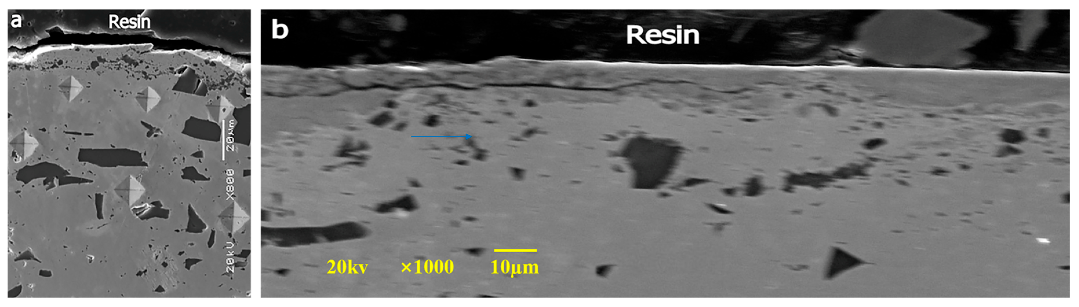
3.4. Morphology of Worn Surface/Subsurface

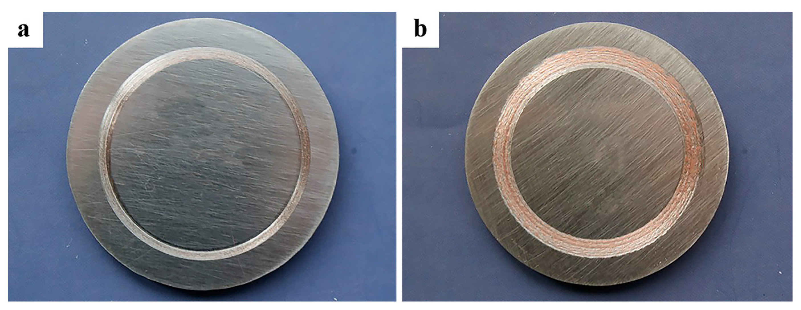
3.4.1. Morphologies of Cu-SiO2 Worn Spot

Figure 7 shows the microstructure of a worn subsurface of Cu-SiO2 sliding against AISI 1045 steel after different sliding distances. The sliding direction is shown in the pictures. The copper grains are curved in the sliding direction and some fractured SiO2 particles can be seen at the top zone of the subsurface. And then, the SiO2 particles are small in the subsurface layer and the copper grains are fine. These longitudinal sections of Cu-SiO2 (parallel to the sliding direction) correspond to the grey/loose area. A distinct layer separated from the bulk can be found at the top subsurface zone of the transversal sections of Cu-SiO2 (perpendicular to the sliding direction) corresponding to the dark area. The layer is provided with a delaminated structure distributed uniformly in thickness. The sliding directions are marked in the pictures.

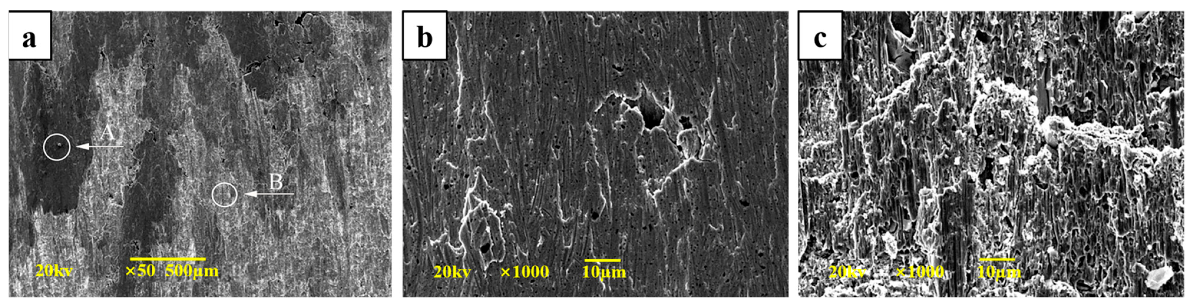
3.4.2. Morphology of 1045 Steel Worn Surface

After 1045 steel slides against Cu-SiO2, a clear brick red layer covers the surface of the circular wear scar area, as Figure 8 shows. The red layer is the Cu-SiO2 transferred layer, with a thickness of approximately 10 μm. As the sliding speed increases, the more Cu-SiO2 comes from the couple transfer to the 1045 steel worn scar area. Energy spectrum analysis shows that there is a large amount of surface metal Cu, but only a small amount of metal Fe, as Figure 9 shows. And the transfer layer has a clear interface with the steel substrate, but its bonding force with the steel substrate is strong and difficult to remove.

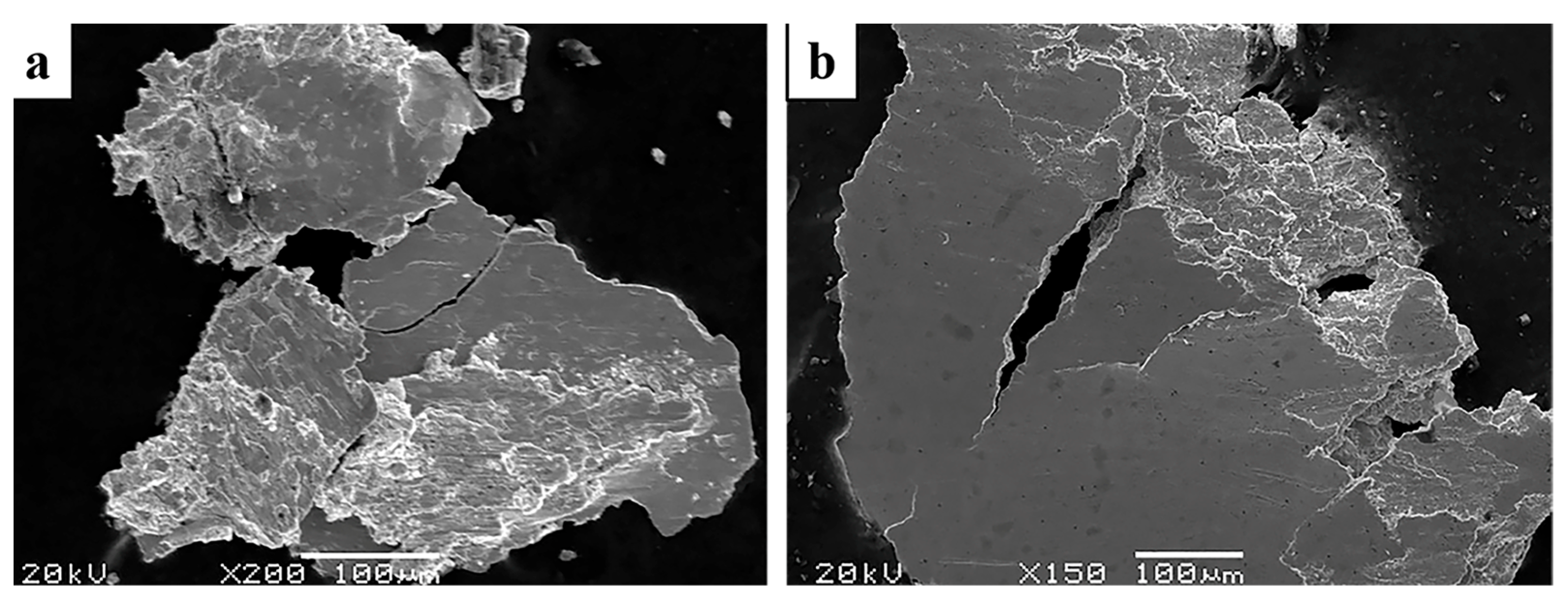
3.5. Morphology of Wear Debris

Wear debris collected at each stage indicates the evolution of the wear regime and mode of material removal. As shown in Figure 10a, typical curl-tailed debris is observed, and it is generated from the coupled steel through the plowing action of hard SiO2 particles in the initial stage. Figure 10b shows the flaky debris with flow impression. This can be generated from the TL on the steel counterbody through the rolling effect in the break-in stage. The blocky and laminar debris are observed in the stable stage, and we deduce that the fracture and delamination of TL occur on the worn surfaces of Cu-SiO2 or steel.

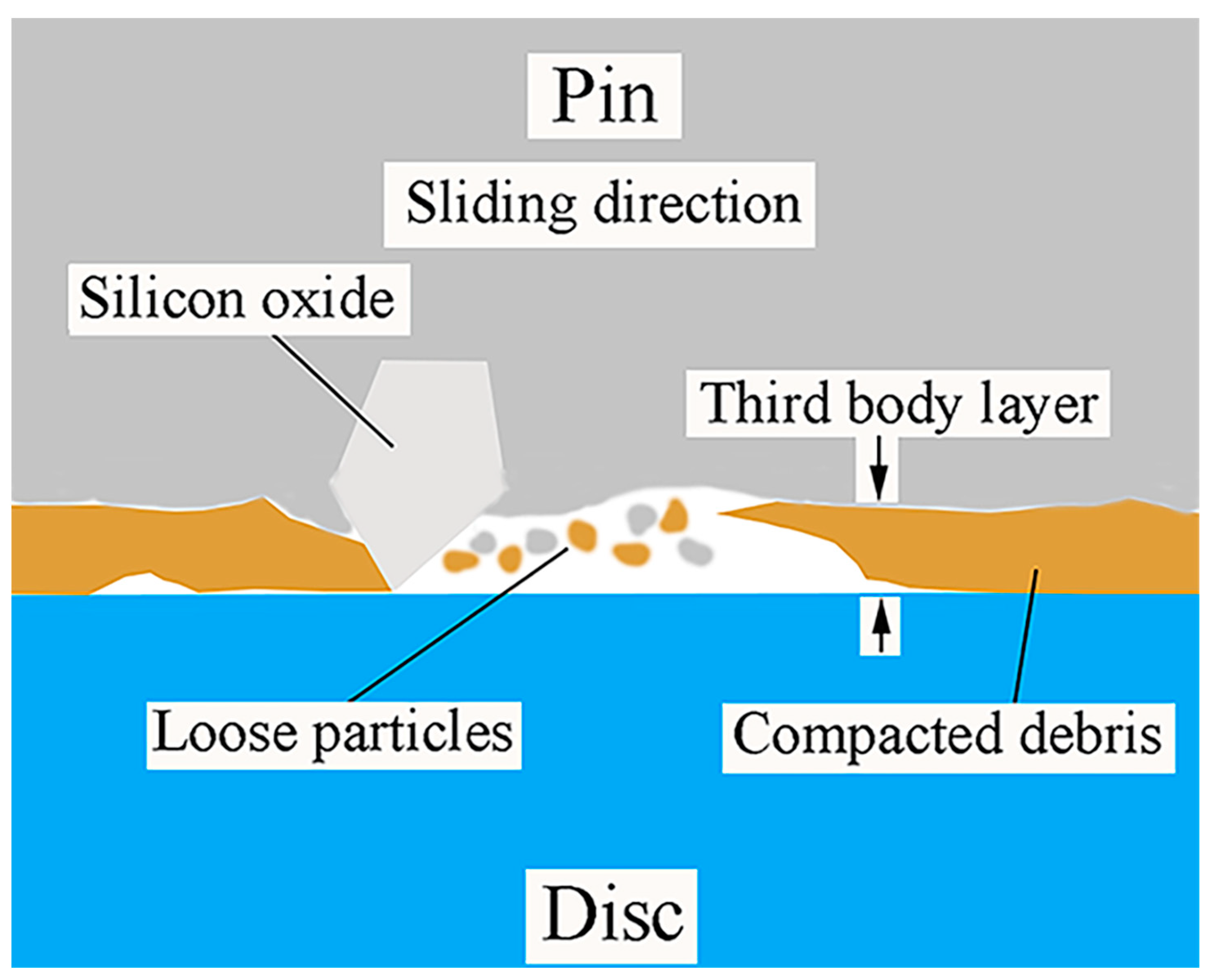
4. Formation Mechanism of Tribolayer

There are two main mechanisms for the formation of abrasive particles and thin layers shed from the substrate material during friction and wear. Under the action of normal pressure and friction force, plastic deformation occurs on the contact surface of the material. When the deformation is accumulated to a certain extent, the material failure of the contact surface falls off in the form of debris and is sandwiched in the friction interface, forming a thin layer under the action of continuous rolling.
The formation mechanism of the third body was investigated for the Cu-SiO2 sintered material. At the beginning of friction, the third body particles are blocked by the SiO2 particles embedded in the matrix and pile up around the SiO2 to form a compaction zone. With the increase in friction time, the number of particles accumulated around the SiO2 particles increases, which increases the area of the third body compaction zone and leads to the increase in the bearing capacity of SiO2 particles. When the load exceeds the load-bearing capacity of the SiO2 particles, the SiO2 particles are broken and the third body compaction zone is crushed, as Figure 11 shows.

5. Discussion

In the above sections, the worn surfaces/subsurface have been characterized. The worn surfaces and subsurface present differences in structure and composition. Friction heat is the key in the present experiment. At 0.56 m/s, the temperature rise in Cu-SiO2 bulk (Tbr) is 24 °C during sliding; the generated friction heat is not enough to make the large-area contact zone of bulk soften and this can be indicated by the morphology of worn surface. The evidence of plastic flow is not obvious and cracks perpendicular to the sliding direction are found. Little copper is transferred to the coupled steel and the wear loss is low for Cu-SiO2. While at 1.68 m/s, the more friction heat is generated, which is reflected by the relative high value of Tbr. Although the recorded bulk temperature near the contact surface of the Cu-SiO2 composite is much lower than the on-set softening point of copper (about 400 °C), the real temperature or flash temperature at the interface is higher than the measured bulk temperature. Hereby, thermal softening can happen at the top subsurface of the Cu-SiO2. We can see the plastic flow is evident in Figure 4b,c. The SiO2 particles are pulled out from the softened bulk and the void is presented. Much softened copper is transferred to the coupled steel (Figure 8b) and the wear loss is high for Cu-SiO2. It can be seen that when the sliding speed is low, the friction interface is basically an isothermal environment and the interface temperature is relatively low, which is not enough to change the intrinsic properties of the material; while, when the sliding speed is high, the friction interface is an adiabatic environment and the friction heat has no time to be discharged from the interface, so that the interface temperature is high and the material is easy to oxidize and change the intrinsic properties of the material.
We have presented the evolution of the tribolayer in morphology and structure. During the initial stage, hard SiO2 particles located at the surface of Cu-SiO2 plow 1045 steel. Abrasive evidence, i.e., tailed debris is produced during sliding. And then, the SiO2 can be fractured or pulled out of the contact zone and the contact surface is rough. The frictional coefficient fluctuates heavily in this stage due to the rough contact surface, and abrasive wear is the dominant mechanism. During the next stage, the plastic flow is promoted by the frictional heating of the Cu bulk indicated by the rise in the near-surface temperature of the Cu-SiO2. This layer is characterized with flow and makes the contact surface become relatively smooth. The friction coefficient is, thereby, relatively stable. A compacted layer covers the worn surface extensively. This layer is separated from the bulk and has a delaminated structure. The flaky and blocky debris can be produced from the contact surface of Cu-SiO2. When the softening of the Cu-SiO2 bulk occurs, the metallic Cu is prone to transfer the steel surface and cover the contact zone. The friction coefficient is relatively stable due to the even contact surface; adhesive wear and delaminated wear are the dominant mechanisms in this stage. A distinct zone is produced at the subsurface of the Cu-SiO2. The contact surface evolves into a similar morphology. But the surface is less rough, comparatively. The contact material is strengthened due to deformation, and it is difficult to remove because of “cold welding”. Laminar debris is produced at the edge of the worn surface of Cu-SiO2 (Figure 9b). The delaminated wear is the predominant mechanism in this stage. When the tribolayer is smooth and compacted, the friction coefficient presents little fluctuation and the bulk temperature rise becomes stabilized. The low bulk temperature indicates the little generation of frictional heating, and the strength and the load carrying ability of the contact material can be maintained; thereby mild wear may be caused.

6. Conclusions

The tribological behaviors of Cu-SiO2 composite sliding against steel at 0.56 m/s–2.24 m/s are investigated. And the influencing mechanisms of sliding speeds associating with frictional heat are discussed.
(1)
Abrasive wear and adhesive wear are the dominant mechanisms at the 0.56 m/s condition.
(2)
Delamination wear and oxidation wear are the dominant wear mechanisms at the 1.68 m/s condition.
(3)
Plastic and thermal deformation cause the evolution in morphology and structure of the tribolayer of Cu-SiO2.
(4)
There is a certain correlation between the friction coefficient and the variation in friction temperature during sliding wear of Cu-SiO2 and 1045 steels. The addition of SiO2, inducing the accumulation of frictional heat at the friction interface, leads to an increase in the average temperature of the contact surface, and induces sticking welding and transfer.

Author Contributions

Writing—original draft preparation, Q.C.; Writing—review and editing, J.S.; data curation, E.X. All authors have read and agreed to the published version of the manuscript.

Funding

This research was funded by National Natural Science Foundation of China, grant number 51405215; the open program of State Key Laboratory of Solid Lubrication, Lanzhou Institute of Chemical Physics, Chinese Academy of Science (LSL-1413).

Data Availability Statement

The datasets generated during this study are available from the corresponding author upon reasonable request.

Conflicts of Interest

The authors declare no conflict of interest.

References

  1. Rigney, D.A. Transfer, mixing and associated chemical and mechanical processes during the sliding of ductile materials. Wear 2000, 245, 1–9. [Google Scholar] [CrossRef]
  2. Rigney, D.A.; Karthikeyan, S. The evolution of tribomaterial during sliding: A brief introduction. Tribol. Lett. 2009, 39, 3–7. [Google Scholar]
  3. Godet, M. The third-body approach: A mechanical view of wear. Wear 1984, 100, 437–452. [Google Scholar] [CrossRef]
  4. Riahi, A.R.; Alpas, A.T. The role of tribo-layers on the sliding wear behaviour of graphitic aluminium matrix composites. Wear 2001, 251, 1396–1407. [Google Scholar] [CrossRef]
  5. Descartes, S.; Berthier, Y. Rheology and flows of solid third bodies: Background and application to an MoS1.6 coating. Wear 2002, 252, 546–556. [Google Scholar] [CrossRef]
  6. Österle, W.; Urban, I. Friction layers and friction films on PMC brake pads. Wear 2004, 257, 215–226. [Google Scholar] [CrossRef]
  7. Emge, A.; Karthikeyan, S.; Rigney, D. The effects of sliding velocity and sliding time on nanocrystalline tribolayer development and properties in copper. Wear 2009, 267, 562–567. [Google Scholar] [CrossRef]
  8. Singh, J.B.; Wen, J.G.; Bellon, P. Nanoscale characterization of the transfer layer formed during dry sliding of Cu-15wt.% Ni-8wt.% Sn bronze alloy. Acta Mater. J. 2008, 56, 3053–3064. [Google Scholar] [CrossRef]
  9. Burton, R.A. Thermal deformation in frictionally heated contact. Wear 1980, 59, 1–20. [Google Scholar] [CrossRef]
  10. Abdel-Aal, H.A. Temperature fields in dry sliding contact by a hybrid laser-speckle technique. Wear 1995, 181–183, 723–729. [Google Scholar]
  11. Yu, J.W.; Gong, Z.L. Analysis to the Thermal mechanism of wear in dry friction condition. Lubr. Eng. J. 2005, 171, 173–176. (In Chinese) [Google Scholar]
  12. Kennedy, F.E. Thermal and thermomechanical effects in dry sliding. Wear 1984, 100, 453–476. [Google Scholar] [CrossRef]
  13. Abdel-Aal, H.A. On the connection of thermal dilatation to protective layer formation in the fretting of metallic tribo-specimens. Wear 2001, 247, 76–87. [Google Scholar] [CrossRef]
  14. Abdel-Aal, H.A. Correlating thermal dilatation to protective layer formation in fretting wear. Int. Commun. Heat Mass Transf. 2001, 28, 97–106. [Google Scholar] [CrossRef]
  15. Kennedy, F.E.; Ballbahadur, A.C.; Lashmore, D.S. The friction and wear of Cu-based silicon carbide particulate metal matrix composites for brake applications. Wear 1997, 203–204, 715–721. [Google Scholar] [CrossRef]
  16. Dhokey, N.; Paretkar, R. Study of wear mechanisms in copper-based SiCp (20% by volume) reinforced composite. Wear 2008, 265, 117–133. [Google Scholar] [CrossRef]
  17. Xiong, X.; Chen, J.; Yao, P.; Li, S.; Huang, B. Friction and wear behaviors and mechanisms of Fe and SiO2 in Cu-based P/M friction materials. Wear 2007, 262, 1182–1186. [Google Scholar] [CrossRef]
  18. Shang, J.; Ma, W.L.; Lu, J.J. Formation of laminar structure under unlubricated friction of Cu-SiO2 composite. Tribol. Lett. J. 2012, 48, 249–254. [Google Scholar] [CrossRef]
  19. Su, L.; Gao, F.; Han, X.; Chen, J. Effect of copper powder third body on tribological property of copper-based friction materials. Tribol. Int. 2015, 90, 420–425. [Google Scholar] [CrossRef]
Figure 1. SEM microstructure of sintered Cu-SiO2 composite.
Crystals 14 00232 g001
Figure 2. Friction coefficient (μ), wear rate (Wr) and bulk temperature (Tbr) of Cu-SiO2 in sliding against 1045 steel at 0.56 m/s–2.24 m/s: (a) Friction coefficient, (b) Wear rate, (c) Near-surface temperature (the inset picture in shows the pin-on-disk tribometer applied in present study).
Crystals 14 00232 g002
Figure 3. Worn surface morphologies of Cu-SiO2 after sliding against 1045 steel at 0.56 m/s: (a) Large area, (b) Zone A, (c) Zone B.
Crystals 14 00232 g003
Figure 4. Worn surface morphologies of Cu-SiO2 after sliding against 1045 steel at 1.68 m/s: (a) Large area, (b) Zone A, (c) Zone B.
Crystals 14 00232 g004
Figure 5. Worn surface XPS of Cu-SiO2 after sliding against 1045 steel at (a) 0.56 m/s, (b) 1.68 m/s.
Crystals 14 00232 g005
Figure 6. Raman of worn surface of Cu-SiO2 in sliding against 1045 steel at (a) 0.56 m/s and (b) 1.68 m/s.
Crystals 14 00232 g006
Figure 7. SEM morphologies of worn surface of Cu-SiO2 in sliding against 1045 steel at (a) 0.56 m/s and (b) 1.68 m/s.
Crystals 14 00232 g007
Figure 8. Macroscopic morphologies of 1045 steel sliding against Cu-SiO2 at (a) 0.56 m/s and (b) 1.68 m/s.
Crystals 14 00232 g008
Figure 9. EDS worn surface of Cu-SiO2 after sliding against 1045 steel at (a) 0.56 m/s and (b) 1.68 m/s.
Crystals 14 00232 g009
Figure 10. SEM worn debris of Cu-SiO2 after sliding against 1045 steel at (a) 0.56 m/s and (b) 1.68 m/s.
Crystals 14 00232 g010
Figure 11. The mechanism of tribolayer formation during Cu-SiO2 sliding against 1045 steel.
Crystals 14 00232 g011
Disclaimer/Publisher’s Note: The statements, opinions and data contained in all publications are solely those of the individual author(s) and contributor(s) and not of MDPI and/or the editor(s). MDPI and/or the editor(s) disclaim responsibility for any injury to people or property resulting from any ideas, methods, instructions or products referred to in the content.

