Article

Size and Temperature Effects on Band Gap Analysis of a Defective Phononic Crystal Beam

1
School of Civil Engineering, Chongqing University, Chongqing 400044, China
2
PowerChina Guiyang Engineering Corporation Limited, Guiyang 550081, China
3
Jiangsu Key Laboratory of Engineering Mechanics, School of Civil Engineering, Southeast University, Nanjing 210096, China
*
Authors to whom correspondence should be addressed.
Crystals 2024, 14(2), 163; https://doi.org/10.3390/cryst14020163
Submission received: 11 January 2024 / Revised: 30 January 2024 / Accepted: 1 February 2024 / Published: 4 February 2024

Abstract

:
In this paper, a new defective phononic crystal (PC) microbeam model in a thermal environment is developed with the application of modified couple stress theory (MCST). By using Hamilton’s principle, the wave equation and complete boundary conditions of a heated Bernoulli–Euler microbeam are obtained. The band structures of the perfect and defective heated PC microbeams are solved by employing the transfer matrix method and supercell technology. The accuracy of the new model is validated using the finite element model, and the parametric analysis is conducted to examine the influences of size and temperature effects, as well as defect segment length, on the band structures of current microbeams. The results indicate that the size effect induces microstructure hardening, while the increase in temperature has a softening impact, decreasing the band gap frequencies. The inclusion of defect cells leads to the localization of elastic waves. These findings have significant implications for the design of microdevices, including applications in micro-energy harvesters, energy absorbers, and micro-electro-mechanical systems (MEMS).

1. Introduction

Phononic crystal (PC) [1,2,3,4] is an artificial composite structure characterized by periodic variations in material parameters or geometric shapes. One significant attribute of PC is the ability to create band gaps in the propagation of elastic waves, which means that elastic waves in certain or all directions within a specified frequency range cannot freely propagate in the structure [5,6,7,8]. If the periodicity of PC is disrupted, one or more dispersion curves, referred to as defect bands, will appear within that gap [9,10,11,12]. Consequently, elastic waves with defect frequencies are localized at these defects, which means that the vibration energy concentrates at specific locations. Although the presence of defect bands does not entirely prevent the propagation of elastic waves within the PC, it allows for the concentration and harvesting of vibrational energy at specific locations. By employing the numerical method, Sigalas [11] revealed for the first time the generation mechanism of defect bands in two-dimensional PCs with geometric defects. Li et al. [13] introduced material defects by replacing materials at different positions of the PC and studied the impact of material properties on the waveguiding and acoustic confinement of the defect PC plate. Yao et al. [14] investigated the impacts of defect configurations, encompassing geometric size and filling fraction, on defect bands within PC plates. Jo et al. [15] discussed the principles of defect band formation and splitting based on PC models with single or double defects.
As the engineering environment grows increasingly complex, traditional PCs face challenges in adapting to changes in external conditions and autonomously adjusting the bandgap frequency and bandwidth post-manufacturing. Currently, researchers have developed various PC models that control the band gap through multi-physics coupling, incorporating mechanisms such as electro-elastic coupling [16,17,18], magneto-elastic coupling [19], and thermo-elastic coupling [20]. Likewise, the defect bands can be actively regulated by controlling the magnetic field [21,22] or electric field [23]. Typically, the environment temperature can significantly influence the performance of the device [24,25]. Temperature variations not only alter the physical properties of materials but also impact the structural stress state through thermal effects, consequently influencing the dynamic behavior of PC. Hu et al. [26] numerically studied the influence of temperature changes on the defect state of two-dimensional PC. Geng et al. investigated the band structure and energy harvesting behavior of PC Timoshenko beams with single [27] or double [28] defects under thermal load.
With the advancement of manufacturing technology, devices are progressively moving towards micronization. However, numerous static [29,30,31,32] and dynamic experiments [33,34] have demonstrated that the prediction of the mechanical behavior of microstructures based on classical continuum mechanics theory significantly deviates from experimental results. The size effect induces distinct mechanical properties in microstructures compared to macrostructures. Currently, many high-order theories are proposed to describe the size effect [35,36,37,38,39,40,41,42,43,44], such as the couple stress theory [45], strain gradient theory [46], non-local elasticity theory [47], surface elasticity theory [48], and reformulated strain gradient elasticity theory [49,50,51]. Utilizing the couple stress theory, Yang et al. established the modified couple stress theory (MCST), which specifically accounts for the symmetric curvature tensor with one additional material parameter for isotropic material. Based on the simplified non-classical theory, the mechanical behaviors of numerous microstructures have been investigated [52,53,54]. However, there is currently no research on one-dimensional defective PC micromodels with temperature effects based on non-classical theory. This paper fills this gap.
This paper studies the band gap characteristics of defective PC microbeams incorporating temperature effects. In Section 2, the wave equation and boundary conditions are obtained based on the MCST. In Section 3, the dispersion curves of perfect and defective heated PC microbeams are solved by using the transfer matrix method (TMM) and supercell technology. In Section 4, the accuracy of the current model is verified with the help of the finite element method. The influence of size effect, thermal effect, and defect segment length on the band gap of the current and classic models is discussed. The mode shapes of the defective heated PC microbeam at the defect frequency are also exhibited to discuss the feasibility of the structure for energy harvesting. The conclusion is given in Section 5.

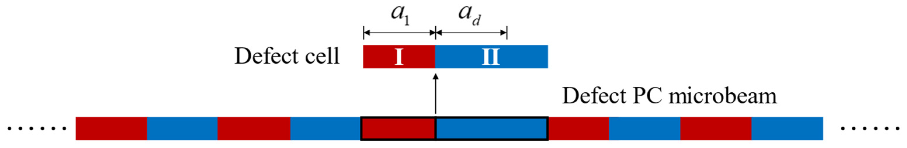
2. Model and Formulation

As depicted in Figure 1, an Euler microbeam subjected to axial thermal load FT with length L, height h, and width b in the Cartesian coordinate system is considered. Because of the temperature variation and boundary conditions, an axial load is generated at both ends of the beam.
According to the Bernoulli–Euler beam theory, the displacements are given as follows [39,55]:
u 1 = w ( x ,   t ) z ,   u 2 = 0 ,   u 3 = w ( x ,   t ) .
where u1, u2, and u3 are the displacements of a point (x, y, z) in the microbeam at time t, respectively. And w denotes the deflection.
Based on the MCST [56,57], the components of the strain and symmetric curvature tensors are defined as
ε i j = 1 2 ( u i , j + u j , i ) ,   χ i j = 1 4 ( e i p q u q , p j + e j p q u q , p i ) ,
where eijk represents the Levi-Civita symbol; ui,j is the derivative of ui with respect to j; uq,pj is the second derivative of uq with respect to p and j; and i, j, p, q = xz. εij and χij are both second-order tensors.
Substituting Equation (1) into Equation (2) yields
ε x x = z 2 w x 2 ,   χ x y = 1 2 2 w x 2 .
The constitutive relations of the heated microbeam composed of isotropic material are written as
σ i j = λ ε k k δ i j + 2 μ ε i j α Δ T ,   m i j = 2 l 2 μ χ i j .
where σij and mij are, respectively, the Cauchy stress and deviatoric couple stresses, λ and μ are the lame constants, δij is the Kronecker symbol, α is the material thermal expansion coefficient, and ΔT represents the temperature rise of the environment. l is the material length scale parameter.
According to Equation (3), Equation (4) can be written as
σ x x = E ( 1 v ) ( 1 + v ) ( 1 2 v ) z 2 w x 2 α Δ T ,   m x y = l 2 μ 2 w x 2 .
where E is the Young’s modulus and v is the Poisson’s ratio.
It is worth noticing that the stress in Equation (5) includes Poisson’s effect on the microbeam. Because only the axial stress σxx is considered in the equilibrium of the microbeam, the strain component εxx is only related to σxx, so that (1 − v)/((1 + v)(1 − 2v)) is equal to 1 in Equation (5).
According to Equations (3) and (5), the strain energy is described by
T U d t = T Ω ( σ x x ε x x + 2 m x y χ x y ) d V d t ,
with Ω being the beam volume.
The kinetic energy of the microbeam can be written as [58]
T K d t = 1 2 T Ω ρ ( u i t u i t ) d V d t ,
where ρ denotes the mass density.
The work carried out by the thermal load of the microbeam without any other external force is given as follows
T W d t = 1 2 T L F T ( w x ) 2 d x d t .
where FT is the axial load produced by temperature rise.
With the application of Hamilton’s principle [58], the relationship of the first variation of the strain energy, kinetic energy, and external work must meet the following balance requirement
δ T [ K ( U W ) ] d t = 0 .
And the first variation of strain and kinetic energy, and virtual work are expressed as
δ T U d t = T M x x ( w x ) | 0 L d t + T M x x x δ w | 0 L d t T L 2 M x x x 2 δ w d x d t + T Y x y x δ w | 0 L d t T Y x y w x | 0 L d t T L 2 Y x y x 2 δ w d x d t ,
δ T K d t = T L ( ρ A 2 w t 2 ρ I 4 w x 2 t 2 ) δ w d x d t ,
δ T W d t = T L F T 2 w x 2 δ w d x d t + T F T w x δ w | 0 L d t ,
where
M x x = A z σ x x d A = E I 2 w x 2 ,   Y x y = A m x y d A = G A l 2 2 w x 2 .
And A = bh is the section area, and I = bh3/12 is the inertia moment.
Substituting Equations (10)–(12) into Equation (9), applying the fundamental lemma of the variation calculus, the governing equation is obtained as
( E I + l 2 G A ) 4 w x 4 + F T 2 w x 2 = ρ A 2 w t 2 ρ I 4 w x 2 t 2 .
And the boundary conditions are expressed as
( E I + l 2 G A ) 3 w x 3 + F T w x = 0   or   w = w ¯   at   x = 0   and   x = L ,
( E I + l 2 G A ) 2 w x 2 = 0   or   w x = w x ¯   at   x = 0   and   x = L .
When l = 0, Equations (14)–(16) will degenerate into the governing equation and boundary conditions of a classical model without the couple stress effect.

3. Solution Methodology for Band Gap

Consider a PC microbeam as shown in Figure 2, which is composed of serval unit cells consisting of two different segments. The lengths of segments Ⅰ and II are a1 and a2, respectively. The lattice constant a of a unit cell is a1 + a2.
For one unit cell of the microbeam in a thermal environment, the length variation caused by ΔT can be given by
Δ x T = ( α 1 a 1 + α 2 a 2 ) Δ T ,
where α1 and α2 are the thermal expansion coefficients of segments Ⅰ and II, respectively. And the length variation resulting from axial thermal load FT is expressed as
Δ x F = ( F T a 1 E 1 A 1 + F T a 2 E 2 A 2 ) .
Due to the periodic boundary conditions of the two ends of a unit cell, adjacent unit cells constrain the axial expansion deformation. Therefore, the sum of the length variations caused by both ΔT and FT is 0, and then the axial thermal load FT can be expressed as
F T = ( α 1 a 1 + α 2 a 2 E 2 A 2 a 1 + E 1 A 1 a 2 ) E 1 E 2 A 1 A 2 Δ T .
With the application of TMM, the dispersion relation of the current heated PC microbeam can be solved.

3.1. TMM for Perfect Heated PC Microbeam

In the case of steady-state vibration, the transverse displacement is written as
w i ( x , t ) = W i ( x ) e i ω t ,
where i is the unit cell number and i2 = −1 is the imaginary unit.
Substituting Equation (20) into Equation (14), the motion equation can be rewritten as
W i ( IV ) γ i W i β i W i = 0 ,
where
γ i = F T ρ i I i ω 2 E i I i + l i 2 G i A i ,   β i = ρ i A i ω 2 E i I i + l i 2 G i A i .
The roots of the characteristic equation of Equation (21) can be obtained as
λ i ( 1 ) = β i + γ i 2 4 γ i 2 ,   λ i ( 2 ) = β i + γ i 2 4 + γ i 2 .
And then, the general solution of Equation (21) is expressed as
W i ( x ) = A i cos ( λ i ( 1 ) x ) + B i sin ( λ i ( 1 ) x ) + C i cosh ( λ i ( 2 ) x ) + D i sinh ( λ i ( 2 ) x ) .
According to the continuity requirements, it is expected that within each unit cell, the deflection, rotation angle, bending moment and shear force on the interface between the end of segment Ⅰ and the beginning of segment II should remain consistent. For the nth unit cell, the continuity conditions within the unit cell can be expressed as
φ n 2 ( 0 ) = φ n 1 ( a 1 ) , φ n 2 ( 0 ) = φ n 1 ( a 1 ) , ( E 2 I 2 G 2 A 2 l 2 2 ) φ n 2 ( 0 ) = ( E 1 I 1 G 1 A 1 l 1 2 ) φ n 1 ( a 1 ) , ( E 2 I 2 G 2 A 2 l 2 2 ) φ n 2 ( 0 ) = ( E 1 I 1 G 1 A 1 l 1 2 ) φ n 1 ( a 1 ) ,
which can be rewritten as a matrix form
K 2 ψ n 2 = H 1 ψ n 1
where 1 and 2 represent segments Ⅰ and II, respectively, and
ψ n i = [ A n i   B n i   C n i   D n i ] T .
In the same way, the continuity conditions of the interface between the nth unit cell and the (n + 1)th unit cell can be written as
K 2 ψ n 2 = H 1 ψ n 1 ,
where
K i = [ 1 0 1 0 0 λ i ( 1 ) 0 λ i ( 2 ) E i ( λ i ( 1 ) ) 2 0 E i ( λ i ( 2 ) ) 2 0 0 E i ( λ i ( 1 ) ) 3 0 E i ( λ i ( 2 ) ) 3 ] ,
H i = [ cos ( λ i ( 1 ) a i ) sin ( λ i ( 1 ) a i ) λ i ( 1 ) sin ( λ i ( 1 ) a i ) λ i ( 1 ) cos ( λ i ( 1 ) a i ) ( E i I i G i A i l i 2 ) ( λ i ( 1 ) ) 2 cos ( λ i ( 1 ) a i ) ( E i I i G i A i l i 2 ) ( λ i ( 1 ) ) 2 sin ( λ i ( 1 ) a i ) ( E i I i G i A i l i 2 ) ( λ i ( 1 ) ) 3 sin ( λ i ( 1 ) a i ) ( E i I i G i A i l i 2 ) ( λ i ( 1 ) ) 3 cos ( λ i ( 1 ) a i )       cosh ( λ i ( 2 ) a i ) sinh ( λ i ( 2 ) a i ) λ i ( 2 ) sinh ( λ i ( 1 ) a i ) λ i ( 2 ) cosh ( λ i ( 2 ) a i ) ( E i I i G i A i l i 2 ) ( λ i ( 2 ) ) 2 cosh ( λ i ( 2 ) a i ) ( E i I i G i A i l i 2 ) ( λ i ( 2 ) ) 2 sinh ( λ i ( 2 ) a i ) ( E i I i G i A i l i 2 ) ( λ i ( 1 ) ) 3 sinh ( λ i ( 2 ) a i ) ( E i I i G i A i l i 2 ) ( λ i ( 2 ) ) 3 cosh ( λ i ( 2 ) a i ) ] .
Combining Equations (26) and (28), it can be written as
ψ ( n + 1 ) 1 = T c ψ n 1 ,
where Tc = K 1 1 H2 K 2 1 H1 is the transfer matrix.
For the periodic structure, with the application of Bloch theorem, it is obtained as
ψ ( n + 1 ) 1 = ψ n 1 e i k a ,
where k is the Bloch wave number of the PC microbeam.
Substituting Equation (31) into Equation (32), the eigenvalue equation is expressed as
( T c e i k a I ) ψ n 1 = 0 ,
In order for Equation (33) to have non-trivial solutions, it needs to satisfy
| T c λ I | = 0 .
where I is a 4 × 4 unit element, and solving Equation (33) with a specified angular frequency yields four eigenvalues, corresponding to four wave numbers k, and then the dispersion relation of the perfect PC microbeam is obtained. For the case where the k values are all non-real numbers, the elastic wave of the corresponding frequency rapidly attenuates in the PC beam and cannot propagate. This frequency range is the band gap.

3.2. TMM for Defect Heated PC Microbeam

As shown in Figure 3, the periodicity of the perfect heated PC microbeam is destroyed by the introduction of a defect cell. For calculating the dispersion relation of the defect-heated PC microbeam, the supercell technique is applied.
Based on the transfer matrix derived in Section 3.1, the transfer matrix for the supercell which consists of serval unit cells is calculated by [27,59]
T s c = T c m T c ( m 1 ) T d T c 2 T c 1 .
where Tci and Td represent the transfer matrices of the ith normal unit cell and the defect cell, respectively.
And for the supercell, the periodic conditions at both ends are expressed as
ψ ( n + 1 ) 1 = ψ n 1 e i k L ,
where L represents the supercell length.
Therefore, the eigenvalue equation of the supercell is written as
( T s c e i k L I ) ψ n 1 = 0 .
By solving Equation (37), the band structure of the defect-heated PC microbeam including the size effect and thermal effect can be obtained.

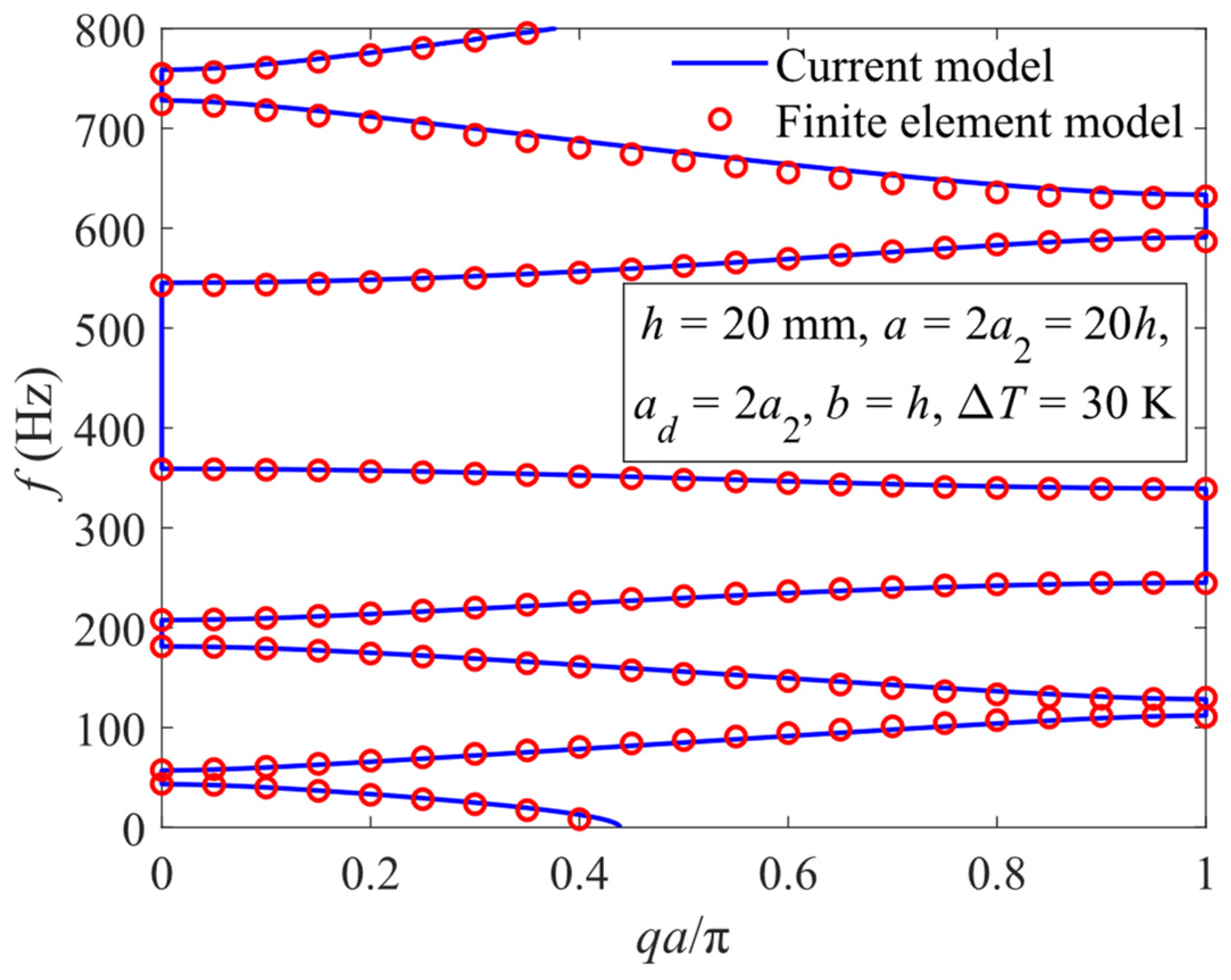
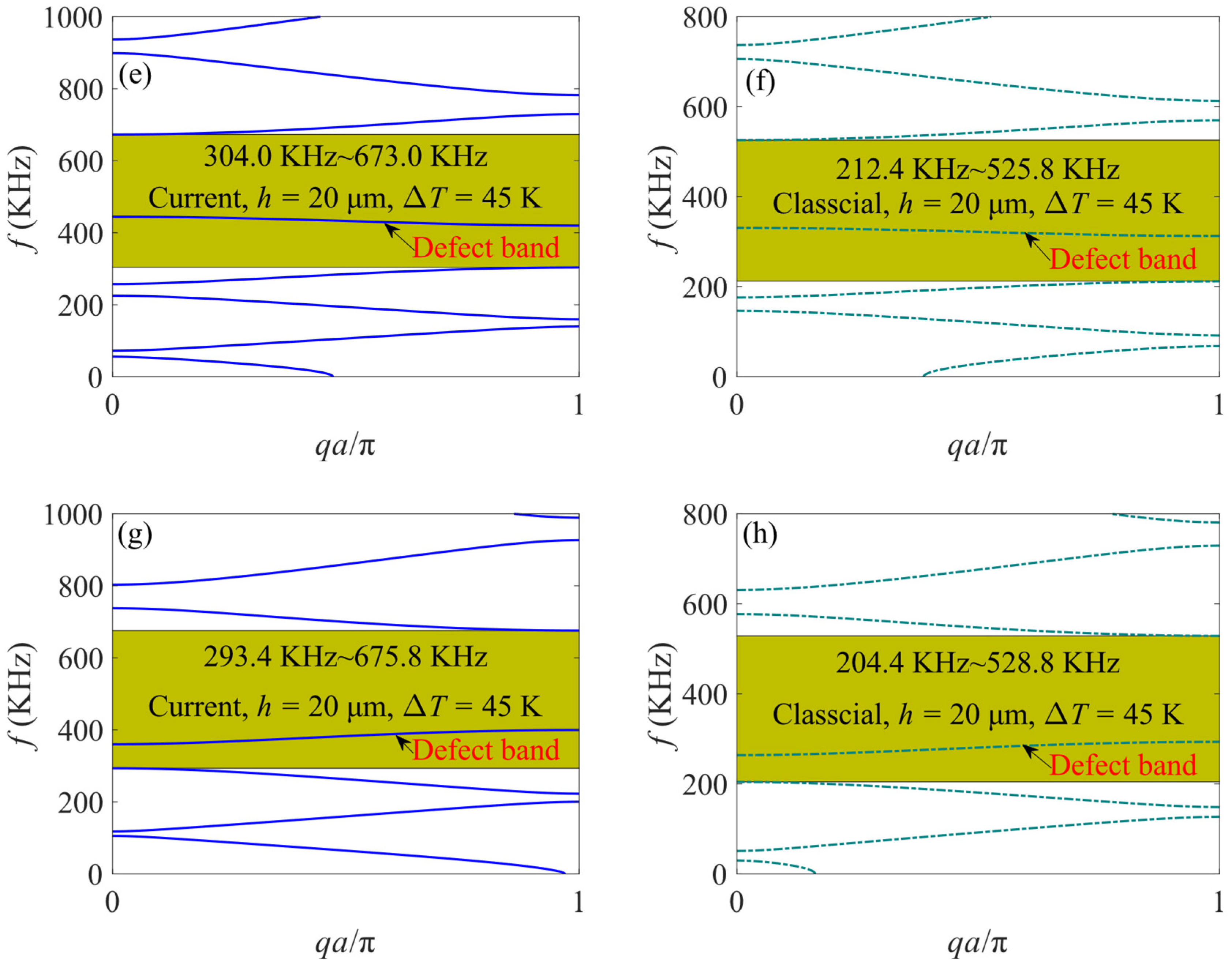
4. Band Gap Analysis

In Section 4, a parametric analysis of the band structure of the heated PC microbeam is performed, and the influence of the size and temperature effects on the band gap and defect band is discussed. The supercell model consists of six normal unit cells and one defect cell which is located at the center of the PC microbeam. For the purpose of obtaining wider band gaps and flatter defect bands to display the results more clearly, the material of segment I is selected to be B4C, and segment II is made of aluminum. The material properties are listed in Table 1. For a normal unit, a1 = a2 = 0.5a, a = 20h, and the beam cross-section is square with width b equal to height h.
To validate the accuracy of the current model, a finite element model of a defective heated PC microbeam is constructed using the thermal stress interface in COMSOL Multiphysics. As COMSOL Multiphysics lacks the capability to capture the size effect of microstructures, both the current model and the finite element model are at a macro scale. The beam height h is specified as 20 mm. The supercell contains seven unit cells, with a defective unit cell in the center and the others are normal unit cells. While the current model incorporates size effects, the finite element model does not account for the effect. Other material properties remain consistent with those in Table 1, and the temperature rise ΔT is set at 30 K.
It is evident from Figure 4 that the dispersion curves of the current model and the finite element model agree well, albeit with some discrepancies at higher frequencies attributed to the inherent high-order stability issue of TMM. Through comparison with the finite element model, the validity of the proposed model has been confirmed. Furthermore, the noticeable consistency in the results of the two defective PC macro-beams, as depicted in Figure 4, underscores that the size effect has a minimal impact on the band structure of the macrostructure.

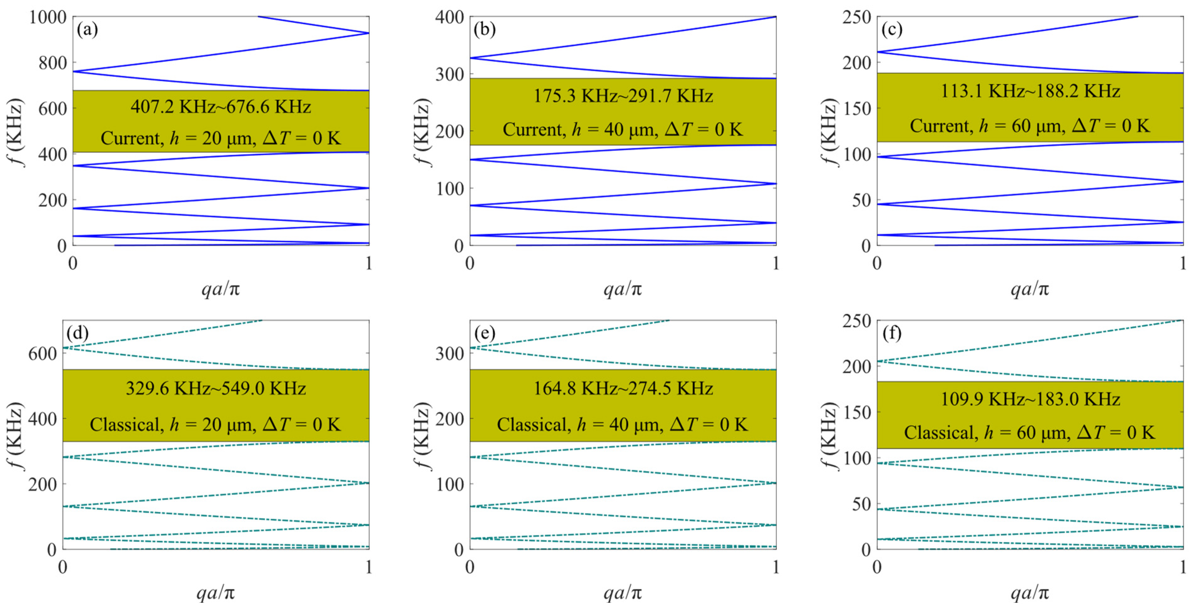
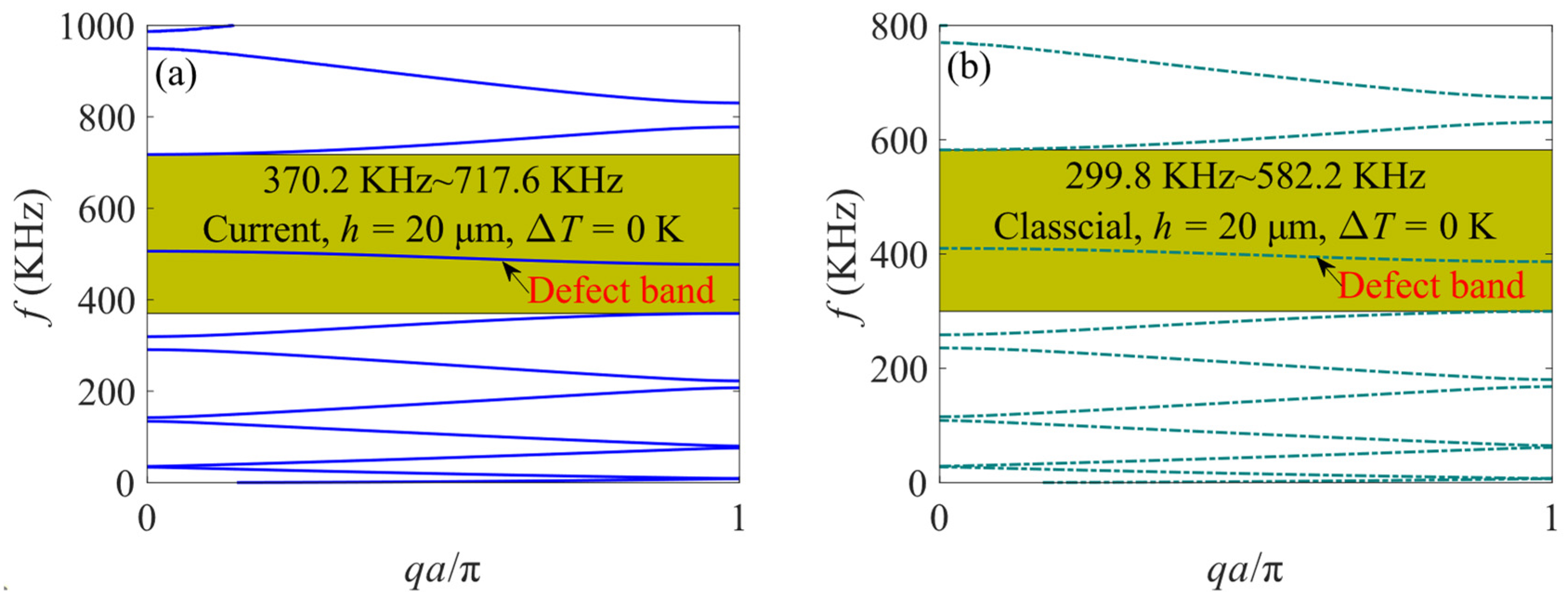
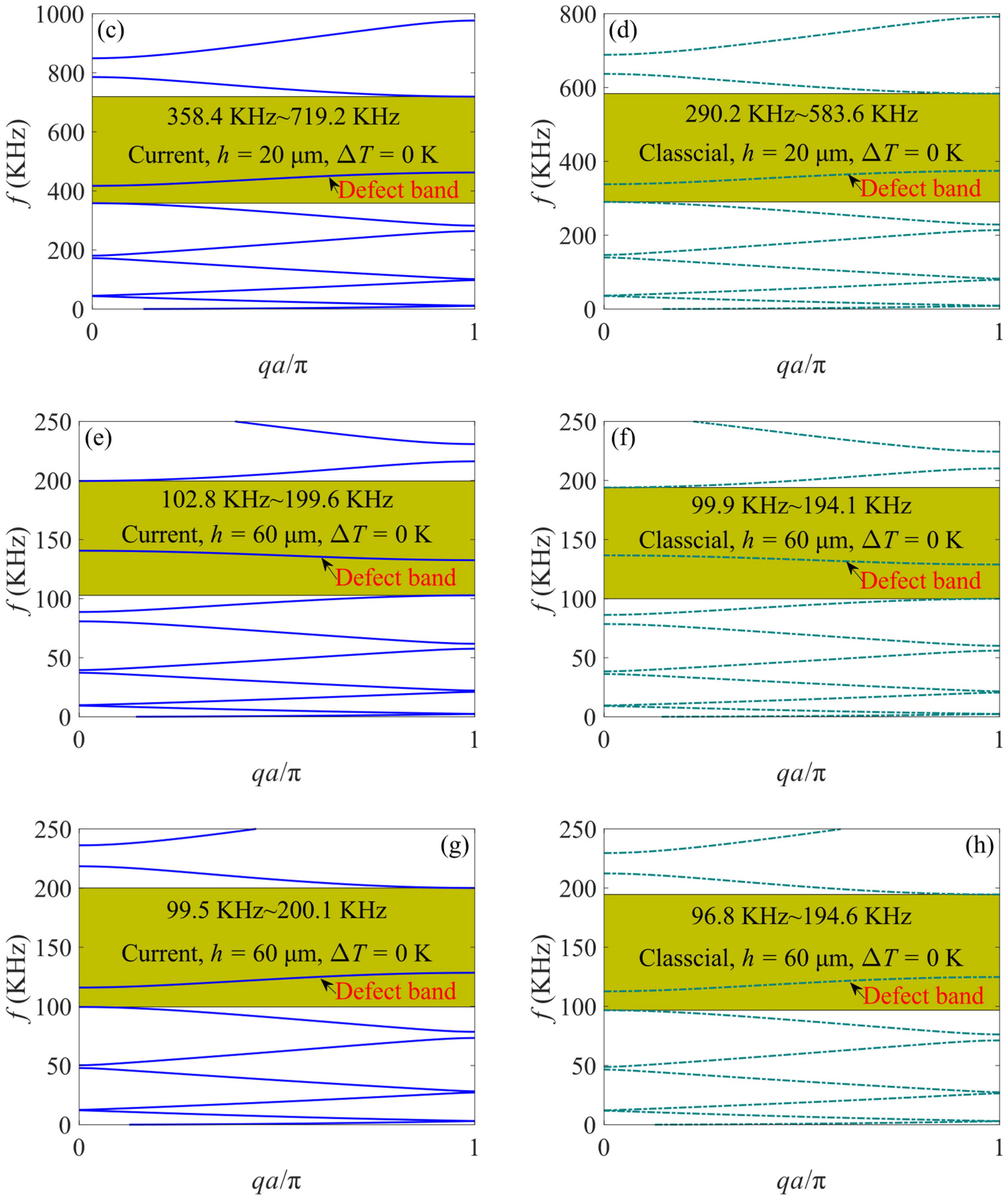
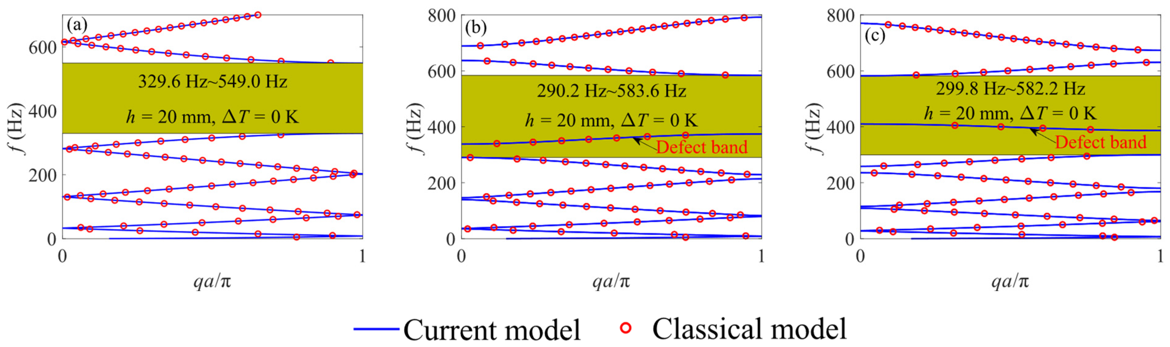
4.1. The Influence of Size Effect

For the purpose of studying the influence of size effect on the band structures of the perfect heated PC microbeam, Figure 5 illustrates the band structure of both the current and classical perfect PC microbeam without any temperature elevation.
From Figure 5, it is obvious that the band gaps appear in both the current and classical models due to the difference in material properties between segments I and II. And the frequencies of dispersion curves predicted by the current PC microbeam are higher than those of the classical one, which means that the size effect increases the stiffness of microstructures. In addition, for B4C and aluminum adopted in this section, the size effect leads to an increase in the stiffness difference between the two materials, so that the bandwidths of the current model are larger than the classical model. With the increase in beam height, the frequencies of the dispersion curves predicted by the current model progressively converge with those of the classical model, and the disparity in band gaps also diminishes. This phenomenon indicates that the size effect induces a stiffening influence solely on PC beams with a microscopic scale while having almost no effect on the macrostructures.
Disrupting the periodicity of the PC microbeam leads to variations in the band structure. A defective cell can be generated in the perfect PC microbeam by changing the length of segment II in this section. Figure 6 displays the band structure of the defective PC microbeam with different beam heights and defect segment lengths in the case of ΔT = 0 K.
In Figure 6a,b, it can be seen that the band gap ranges of current and classical models are both broadened when the periodicity of the perfect PC microbeam is destroyed. For the case where ad > a2, the frequencies of the eighth dispersion curve decrease and appear alone in the band gap, which is called the defect band, while the ninth dispersion curve becomes the upper boundary of the band gap. Similarly, in Figure 6c,d, when ad < a2, the bandwidths of the current and classical models are also expanded, and a defect band appears within the band gap, which is the seventh dispersion curve with increasing frequencies, and the sixth dispersion curve becomes the lower boundary of the band gap. In addition, the band structures of the defective PC microbeams also open some narrow band gaps at low frequencies. By comparing Figure 6a–d with Figure 6e–h, it is found that for any length of a defective segment, the size effect affects the frequencies of the band gap and defect band of the defective PC microbeam. Furthermore, it is noted that the impact of the size effect becomes more pronounced as the size of the beam decreases, which aligns with the trend observed in Figure 5.
Figure 7 plots the band structures of the perfect PC beam and defective PC beam at the macroscale. It can be found that the dispersion curves of the classical and current models are almost completely consistent, which once again proves that the size effect has almost no impact on the dynamic response of the macrostructure.

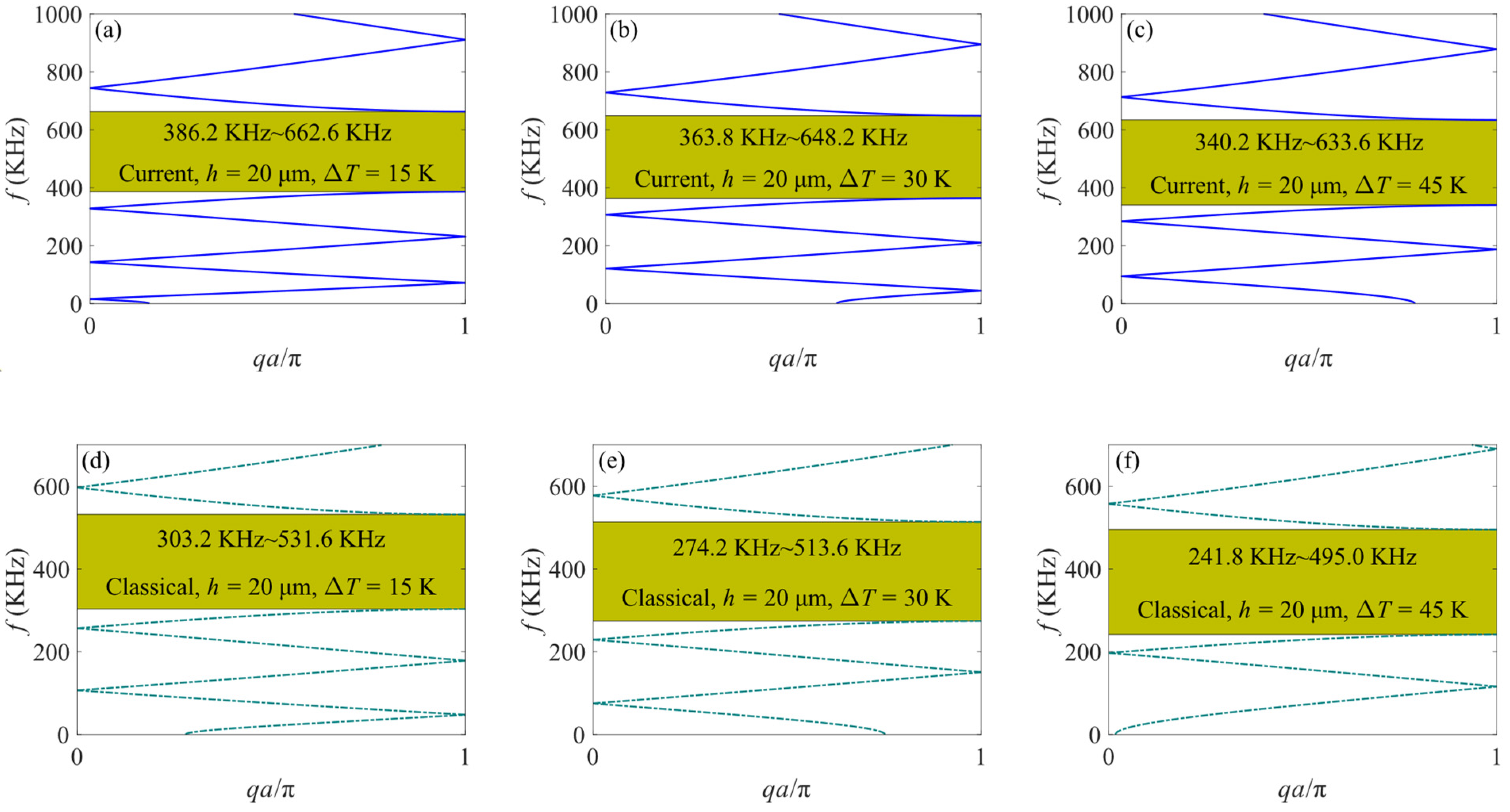
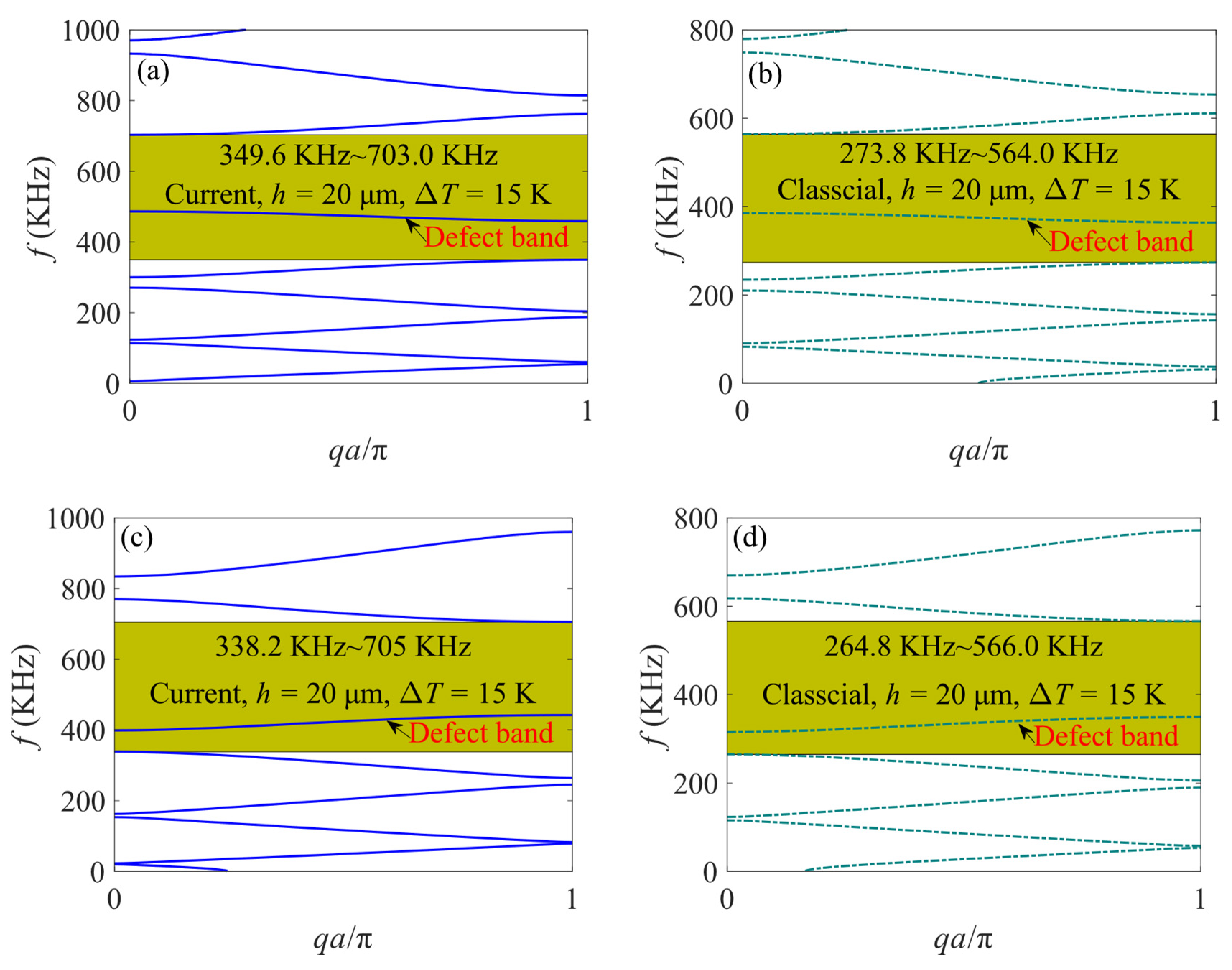
4.2. The Influence of Temperature Effect

The dispersion curves obtained from Equations (33) and (37) include the influence of temperature rise. In order to explore the impact of the thermal effect on the band gap of a perfect PC microbeam, Figure 8 exhibits the band structures of the perfect PC microbeam with various temperature rises.
Figure 8 reveals that with increasing temperature, the upper and lower frequency bounds of the band gap for both the current and classical models decrease. This phenomenon is attributed to the axial thermal force generated by the temperature rise, leading to the softening effect of the microbeam. Furthermore, elevated temperatures contribute to an expanded bandwidth in both the current and classical models. This is a consequence of the higher thermal expansion coefficient of aluminum compared to B4C, so that under the same temperature rise conditions, the axial thermal force in aluminum with lower stiffness is greater, accentuating the material stiffness disparity. Consistent with the trend observed in Figure 5, the frequencies of dispersion curves predicted by the current microbeam model consistently surpass those of the classical model, which underscores that the size effect cannot be disregarded when calculating the band structure of microstructures.
To investigate the impact of temperature effects on the band structure of a heated defective supercell, Figure 9 illustrates the band structure of a heated defective PC microbeam with varying defect segment lengths under different temperature rise conditions. As observed in Figure 9, the introduction of the defective cell results in expanded bandwidths, and the length of the defect segment significantly influences the frequencies of both the band gap and the defect band. With increasing temperature, the frequency of the defect band undergoes a downward shift, aligning with the trend seen in the dispersion curve changes depicted in Figure 8. Furthermore, under arbitrary defect segment length and temperature rise conditions, there are obvious differences between the band structures of the current model and the classical model with the same conditions. This finding once again underscores the significance of the size effect in accurately predicting the mechanical response of microstructures.
When segment II, characterized by lower stiffness, undergoes elongation in the defective unit cell, as depicted in Figure 10a,c, the mode shape of the defective PC microbeam model at the frequency of the defect band exhibits an antisymmetric shape with the midpoint of segment II in the defect segment as the center. This results in the most pronounced bending at the two ends of the defect segment. And when the defect segment is shortened, as shown in Figure 10b,d, the mode shape of the defect PC microbeam becomes symmetrical, with the midpoint of the defective segment serving as the center. The curvature of the microbeam reaches its maximum at the midpoint of the defect segment. Figure 10 illustrates that the flexural wave energy is concentrated predominantly near the defect segment. For various defect modes, piezoelectric materials could be strategically attached at specific positions to capture and convert the vibrational energy into electrical energy. Moreover, through a comparison of Figure 10a,b and Figure 10c,d, it becomes apparent that temperature variations have almost no impact on the mode shape of the heated defective PC microbeam.
For the purpose of further analyzing the localization effect of the defective PC microbeam, the quantified method of energy localization can be found in [63]. The localization rate τ is defined by the following equation:
τ ( % ) = 100 | w i w max |
where wi is the deflection of ith point on the centroidal axis, and wmax is the maximum deflection.
Since temperature variation has no effect on the mode shape of the current defective PC microbeam, Figure 11 only displays the phenomenon of displacement localization of the defective PC microbeam with different defect cell lengths under the condition of ΔT = 15 K. As shown in Figure 11, under different lengths of the segment II of defect cell, the localization rate reaches the maximum value near the defect cell. This phenomenon fully demonstrates that the defective PC microbeam has a localization effect and can achieve energy harvesting at a specific location.

5. Conclusions

This paper establishes a theoretical model for a heated defective PC microbeam considering both size and thermal effects based on the MCST. Utilizing TMM and supercell technology, the band structures of heated perfect and defective microbeams are solved. The accuracy of the presented model is verified by comparing the results with a finite element model developed by COMSOL Multiphysics. Using parametric analysis, the influence of size effect, defect segment length, and temperature rise on the band structures and mode shapes of the current and classical models is discussed. The prediction results show the following:
  • Size effects significantly impact the band structure of the PC microbeam, leading to increased stiffness and higher band gap frequencies. However, the size effect is negligible on the macrostructure.
  • The introduction of defect cells widens the band gap of the defective PC microbeam, revealing a smooth dispersion curve within the band gap known as the defect band.
  • Temperature rises will cause thermal axial forces to appear at both ends of unit cells, leading to a decrease in band gaps and defect band frequencies for both current and classical models.
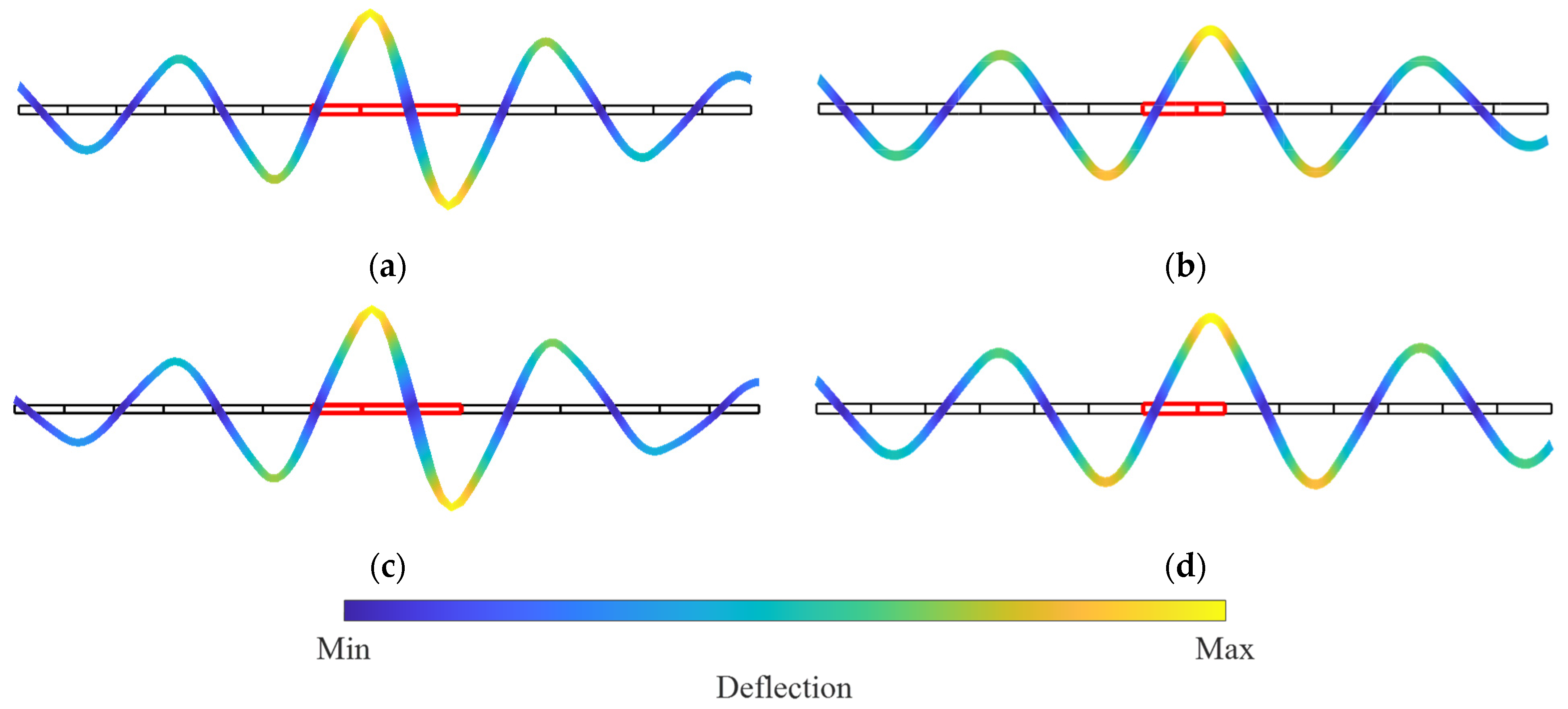
  • Different defect modes result in a distinct mode shape of the defective PC microbeam at the frequency of the defect band. Elongation of the defect segment with lower stiffness produces an antisymmetric mode shape while shortening the defect segment corresponds to a symmetric mode shape. The mode shape of the heated defective PC microbeam remains largely unaffected by temperature.
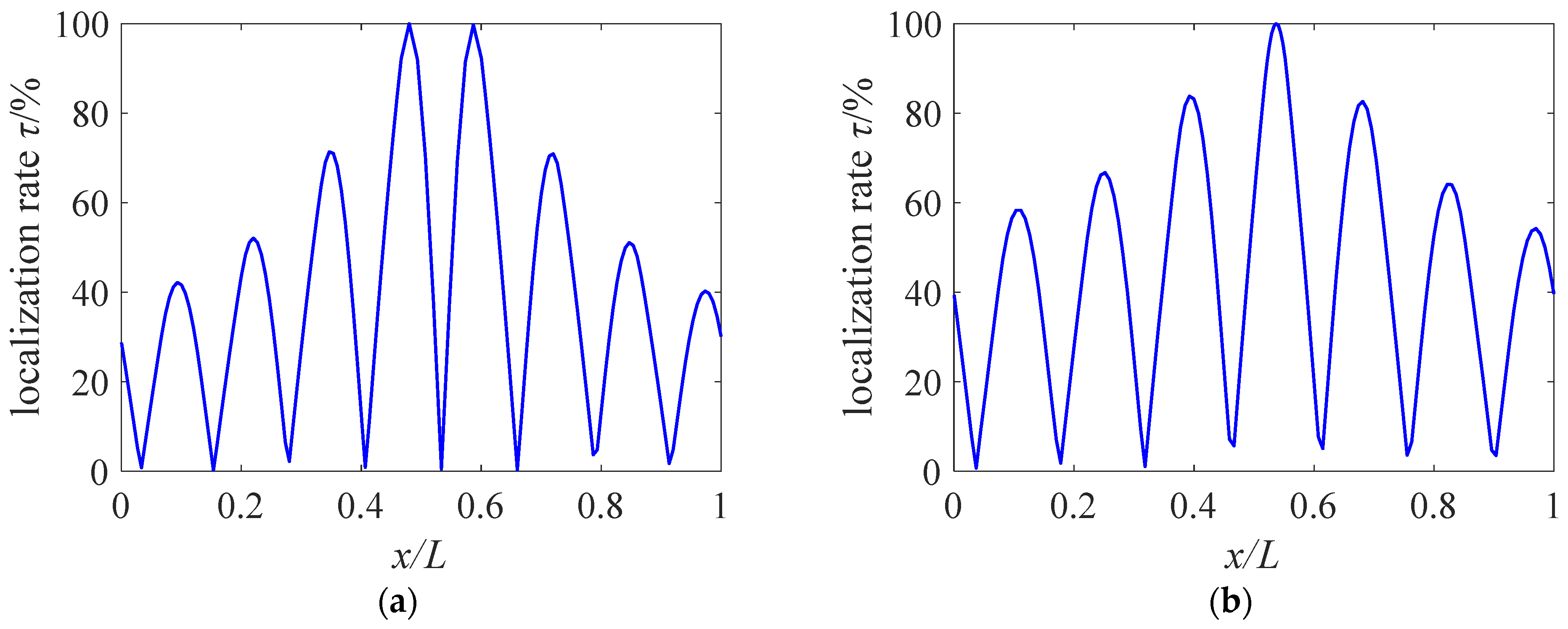
  • The vibration energy will be concentrated near the defective unit cells, which is conducive to energy collection or absorption at specific locations.
The results presented in this paper establish a valuable theoretical foundation with potential implications for the design and engineering applications of various micro-devices, including energy harvesters, micro-sensors, and micro-electro-mechanical systems. The findings contribute to the broader field of micro-scale mechanics and may guide future advancements in the development and application of micro-scale technologies.

Author Contributions

Conceptualization, writing—review and editing and supervision, J.H. and S.G.; project administration, J.H.; validation, S.G.; methodology, B.Y. and S.W.; writing—original draft preparation, B.Y. and S.W. All authors have read and agreed to the published version of the manuscript.

Funding

The work reported here is funded by the Ministry of Housing and Urban-Rural Development Science and Technology Research Program (International Corporation) (grant number 2022-H-003) and the POWERCHINA Science and Technology Research Project (grant number DJ-ZDXM-2020-28).

Data Availability Statement

Data are contained within the article.

Conflicts of Interest

The author Bin Yao was employed by the company PowerChina Guiyang Engineering Corporation Limited. The remaining authors declare that the research was conducted in the absence of any commercial or financial relationships that could be construed as a potential conflict of interest.

References

  1. Kushwaha, M.S.; Halevi, P.; Martínez, G.; Dobrzynski, L.; Djafari-Rouhani, B. Theory of Acoustic Band Structure of Periodic Elastic Composites. Phys. Rev. B 1994, 49, 2313. [Google Scholar] [CrossRef]
  2. Liu, J.; Guo, H.; Wang, T. A Review of Acoustic Metamaterials and Phononic Crystals. Crystals 2020, 10, 305. [Google Scholar] [CrossRef]
  3. Zhang, G.Y.; Gao, X.L. Band gaps for wave propagation in 2-D periodic three-phase composites with coated star-shaped inclusions and an orthotropic matrix. Compos. Part B Eng. 2020, 182, 107319. [Google Scholar] [CrossRef]
  4. Zhang, G.Y.; He, Z.Z.; Qin, J.W.; Hong, J. Magnetically Tunable Bandgaps in Phononic Crystal Nanobeams Incorporating Microstructure and Flexoelectric Effects. Appl. Math. Model. 2022, 111, 554–566. [Google Scholar] [CrossRef]
  5. Plisson, J.; Pelat, A.; Gautier, F.; Garcia, V.R.; Bourdon, T. Experimental Evidence of Absolute Bandgaps in Phononic Crystal Pipes. Appl. Phys. Lett. 2020, 116, 201902. [Google Scholar] [CrossRef]
  6. Faiz, M.S.; Addouche, M.; Zain, A.R.M.; Siow, K.S.; Chaalane, A.; Khelif, A. Experimental Demonstration of a Multichannel Elastic Wave Filter in a Phononic Crystal Slab. Appl. Sci. 2020, 10, 4594. [Google Scholar] [CrossRef]
  7. Ozer, Z.; Demir, M.; Mamedov, A.M.; Ozbay, E. Band Structure of Phononic Crystal Consist of Hollow Aluminum Cylinders in Different Media; Finite Element Analysis. IOP Conf. Ser. Mater. Sci. Eng. 2019, 613, 012018. [Google Scholar] [CrossRef]
  8. Sun, Y.J.; Yu, Y.J.; Zuo, Y.Y.; Qiu, L.L.; Dong, M.M.; Ye, J.T.; Yang, J. Band Gap and Experimental Study in Phononic Crystals with Super-Cell Structure. Results Phys. 2019, 13, 102200. [Google Scholar] [CrossRef]
  9. Wu, F.; Hou, Z.; Liu, Z.; Liu, Y. Point Defect States in Two-Dimensional Phononic Crystals. Phys. Lett. A 2001, 292, 198–202. [Google Scholar] [CrossRef]
  10. Jiang, P.; Wang, X.P.; Chen, T.N.; Zhu, J. Band Gap and Defect State Engineering in a Multi-Stub Phononic Crystal Plate. J. Appl. Phys. 2015, 117, 154301. [Google Scholar] [CrossRef]
  11. Sigalas, M.M. Elastic Wave Band Gaps and Defect States in Two-Dimensional Composites. J. Acoust. Soc. Am. 1997, 101, 1256–1261. [Google Scholar] [CrossRef]
  12. Zhang, G.Y.; Gao, X.Y.; Wang, S.P.; Hong, J. Bandgap and Its Defect Band Analysis of Flexoelectric Effect in Phononic Crystal Plates. Eur. J. Mech. A/Solids 2024, 104, 105192. [Google Scholar] [CrossRef]
  13. Li, Y.; Chen, T.; Wang, X.; Ma, T.; Jiang, P. Acoustic Confinement and Waveguiding in Two-Dimensional Phononic Crystals with Material Defect States. J. Appl. Phys. 2014, 116, 024904. [Google Scholar] [CrossRef]
  14. Yao, Z.J.; Yu, G.L.; Wang, Y.S.; Shi, Z.F. Propagation of Bending Waves in Phononic Crystal Thin Plates with a Point Defect. Int. J. Solids Struct. 2009, 46, 2571–2576. [Google Scholar] [CrossRef]
  15. Jo, S.H.; Yoon, H.; Shin, Y.C.; Youn, B.D. Revealing Defect-Mode-Enabled Energy Localization Mechanisms of a One-Dimensional Phononic Crystal. Int. J. Mech. Sci. 2022, 215, 106950. [Google Scholar] [CrossRef]
  16. Kherraz, N.; Chikh-Bled, F.H.; Sainidou, R.; Morvan, B.; Rembert, P. Tunable Phononic Structures Using Lamb Waves in a Piezoceramic Plate. Phys. Rev. B 2019, 99, 094302. [Google Scholar] [CrossRef]
  17. Chen, S.; Wen, J.; Wang, G.; Yu, D.; Wen, X. Improved Modeling of Rods with Periodic Arrays of Shunted Piezoelectric Patches. J. Intell. Mater. Syst. Struct. 2012, 23, 1613–1621. [Google Scholar] [CrossRef]
  18. Wang, Y.; Zhang, C.; Chen, W.; Li, Z.; Golub, M.V.; Fomenko, S.I. Precise and Target-Oriented Control of the Low-Frequency Lamb Wave Bandgaps. J. Sound Vib. 2021, 511, 116367. [Google Scholar] [CrossRef]
  19. Zhang, S.; Gao, Y. Gap Evolution of Lamb Wave Propagation in Magneto-Elastic Phononic Plates with Pillars and Holes by Modulating Magnetic Field and Stress Loadings. J. Appl. Phys. 2018, 124, 244102. [Google Scholar] [CrossRef]
  20. Bian, Z.; Peng, W.; Song, J. Thermal Tuning of Band Structures in a One-Dimensional Phononic Crystal. J. Appl. Mech. 2014, 81, 041008. [Google Scholar] [CrossRef]
  21. Gu, C.; Jin, F. Research on the Tunability of Point Defect Modes in a Two-Dimensional Magneto-Elastic Phononic Crystal. J. Phys. D Appl. Phys. 2016, 49, 175103. [Google Scholar] [CrossRef]
  22. Deng, T.; Zhang, S.; Gao, Y. Tunability of Band Gaps and Energy Harvesting Based on the Point Defect in a Magneto-Elastic Acoustic Metamaterial Plate. Appl. Phys. Express 2020, 13, 015503. [Google Scholar] [CrossRef]
  23. Shakeri, A.; Darbari, S.; Moravvej-Farshi, M.K. Designing a Tunable Acoustic Resonator Based on Defect Modes, Stimulated by Selectively Biased PZT Rods in a 2D Phononic Crystal. Ultrasonics 2019, 92, 8–12. [Google Scholar] [CrossRef]
  24. Qu, Y.L.; Zhang, G.Y.; Gao, X.L.; Jin, F. A New Model for Thermally Induced Redistributions of Free Carriers in Centrosymmetric Flexoelectric Semiconductor Beams. Mech. Mater. 2022, 171, 104328. [Google Scholar] [CrossRef]
  25. Zhang, G.Y.; Guo, Z.W.; Qu, Y.L.; Gao, X.L.; Jin, F. A New Model for Thermal Buckling of an Anisotropic Elastic Composite Beam Incorporating Piezoelectric, Flexoelectric and Semiconducting Effects. Acta Mech. 2022, 233, 1719–1738. [Google Scholar] [CrossRef]
  26. Hu, A.; Zhang, X.; Wu, F.; Yao, Y.; Cheng, C.; Huang, P. Temperature Effects on the Defect States in Two-Dimensional Phononic Crystals. Phys. Lett. A 2014, 378, 2239–2244. [Google Scholar] [CrossRef]
  27. Geng, Q.; Cai, T.; Li, Y. Flexural Wave Manipulation and Energy Harvesting Characteristics of a Defect Phononic Crystal Beam with Thermal Effects. J. Appl. Phys. 2019, 125, 035103. [Google Scholar] [CrossRef]
  28. Geng, Q.; Wang, T.; Wu, L.; Li, Y. Defect Coupling Behavior and Flexural Wave Energy Harvesting of Phononic Crystal Beams with Double Defects in Thermal Environments. J. Phys. D Appl. Phys. 2021, 54, 225501. [Google Scholar] [CrossRef]
  29. Lam, D.C.C.; Yang, F.; Chong, A.C.M.; Wang, J.; Tong, P. Experiments and Theory in Strain Gradient Elasticity. J. Mech. Phys. Solids 2003, 51, 1477–1508. [Google Scholar] [CrossRef]
  30. Liebold, C.; Müller, W.H. Comparison of Gradient Elasticity Models for the Bending of Micromaterials. Comput. Mater. Sci. 2016, 116, 52–61. [Google Scholar] [CrossRef]
  31. Patel, B.N.; Srinivasan, S.M. Novel Nickle Foil Micro-Bend Tests and the Need for a Relook at Length Scale Parameter’s Numerical Value. Mech. Adv. Mater. Struct. 2022, 29, 3924–3933. [Google Scholar] [CrossRef]
  32. Choi, J.H.; Kim, H.; Kim, J.Y.; Lim, K.H.; Lee, B.C.; Sim, G.D. Micro-Cantilever Bending Tests for Understanding Size Effect in Gradient Elasticity. Mater. Des. 2022, 214, 110398. [Google Scholar] [CrossRef]
  33. Li, Z.; He, Y.; Lei, J.; Han, S.; Guo, S.; Liu, D. Experimental Investigation on Size-Dependent Higher-Mode Vibration of Cantilever Microbeams. Microsyst. Technol. 2019, 25, 3005–3015. [Google Scholar] [CrossRef]
  34. Lei, J.; He, Y.; Guo, S.; Li, Z.; Liu, D. Size-Dependent Vibration of Nickel Cantilever Microbeams: Experiment and Gradient Elasticity. AIP Adv. 2016, 6, 105202. [Google Scholar] [CrossRef]
  35. Zhang, G.Y.; Qu, Y.L.; Guo, Z.W.; Jin, F. Magnetically Induced Electric Potential in First-Order Composite Beams Incorporating Couple Stress and Its Flexoelectric Effects. Acta Mech. Sin. 2021, 37, 1509–1519. [Google Scholar] [CrossRef]
  36. Zhang, G.Y.; Gao, X.L. A Non-Classical Kirchhoff Rod Model Based on the Modified Couple Stress Theory. Acta Mech. 2019, 230, 243–264. [Google Scholar] [CrossRef]
  37. Qu, Y.L.; Zhang, G.Y.; Fan, Y.M.; Jin, F. A Non-Classical Theory of Elastic Dielectrics Incorporating Couple Stress and Quadrupole Effects: Part I – Reconsideration of Curvature-Based Flexoelectricity Theory. Math. Mech. Solids 2021, 26, 1647–1659. [Google Scholar] [CrossRef]
  38. Chen, J.B.; Qu, Y.L.; Guo, Z.W.; Li, D.B.; Zhang, G.Y. A One-Dimensional Model for Mechanical Coupling Metamaterials Using Couple Stress Theory. Math. Mech. Solids 2023, 28, 2732–2755. [Google Scholar] [CrossRef]
  39. Zhang, G.Y.; Gao, X.L.; Zheng, C.Y.; Mi, C.W. A Non-Classical Bernoulli-Euler Beam Model Based on a Simplified Micromorphic Elasticity Theory. Mech. Mater. 2021, 161, 103967. [Google Scholar] [CrossRef]
  40. Zhang, G.Y.; Gao, X.L. A Non-Classical Model for First-Ordershear Deformation Circular Cylindrical Thin Shells Incorporating Microstructure and Surface Energy Effects. Math. Mech. Solids 2021, 26, 1294–1319. [Google Scholar] [CrossRef]
  41. Zhang, G.Y.; Gao, X.L.; Littlefield, A.G. A Non-Classical Model for Circular Cylindrical Thin Shells Incorporating Microstructure and Surface Energy Effects. Acta Mech. 2021, 232, 2225–2248. [Google Scholar] [CrossRef]
  42. Qu, Y.L.; Li, P.; Zhang, G.Y.; Jin, F.; Gao, X.L. A Microstructure-Dependent Anisotropic Magneto-Electro-Elastic Mindlin Plate Model Based on an Extended Modified Couple Stress Theory. Acta Mech. 2020, 231, 4323–4350. [Google Scholar] [CrossRef]
  43. Qu, Y.; Li, P.; Jin, F. A General Dynamic Model Based on Mindlin’s High-Frequency Theory and the Microstructure Effect. Acta Mech. 2020, 231, 3847–3869. [Google Scholar] [CrossRef]
  44. Qu, Y.; Li, P.; Jin, F. A General Dynamic Theoretical Model of Elastic Micro-Structures with Consideration of Couple Stress Effects and Its Application in Mechanical Analysis of Size-Dependent Properties. Acta Mech. 2020, 231, 471–488. [Google Scholar] [CrossRef]
  45. Kolter, W.T. Couple Stresses in the Theory of Elasticity. Proc. K. Ned. Akad. Wet. B 1964, 67, 17–44. [Google Scholar]
  46. Mindlin, R.D.; Eshel, N.N. On First Strain-Gradient Theories in Linear Elasticity. Int. J. Solids Struct. 1968, 4, 109–124. [Google Scholar] [CrossRef]
  47. Eringen, A.C. Nonlocal Polar Elastic Continua. Int. J. Eng. Sci. 1972, 10, 1–16. [Google Scholar] [CrossRef]
  48. Gurtin, M.E.; Ian Murdoch, A. A Continuum Theory of Elastic Material Surfaces. Arch. Ration. Mech. Anal. 1975, 57, 291–323. [Google Scholar] [CrossRef]
  49. Zhang, G.Y.; Gao, X.L. A New Bernoulli–Euler Beam Model Based on a Reformulated Strain Gradient Elasticity Theory. Math. Mech. Solids 2020, 25, 630–643. [Google Scholar] [CrossRef]
  50. Hong, J.; Wang, S.P.; Zhang, G.Y.; Mi, C.W. Bending, Buckling and Vibration Analysis of Complete Microstructure-Dependent Functionally Graded Material Microbeams. Int. J. Appl. Mech. 2021, 13, 2150057. [Google Scholar] [CrossRef]
  51. Wang, S.P.; Hong, J.; Wei, D.; Zhang, G.Y. Bending and Wave Propagation Analysis of Axially Functionally Graded Beams Based on a Reformulated Strain Gradient Elasticity Theory. Appl. Math. Mech. Engl. Ed. 2023, 44, 1803–1820. [Google Scholar] [CrossRef]
  52. Zhang, G.Y.; Qu, Y.L.; Gao, X.L.; Jin, F. A Transversely Isotropic Magneto-Electro-Elastic Timoshenko Beam Model Incorporating Microstructure and Foundation Effects. Mech. Mater. 2020, 149, 103412. [Google Scholar] [CrossRef]
  53. Hong, J.; Wang, S.P.; Zhang, G.Y.; Mi, C.W. On the Bending and Vibration Analysis of Functionally Graded Magneto-Electro-Elastic Timoshenko Microbeams. Crystals 2021, 11, 1206. [Google Scholar] [CrossRef]
  54. Hong, J.; Wang, S.P.; Qiu, X.Y.; Zhang, G.Y. Bending and Wave Propagation Analysis of Magneto-Electro-Elastic Functionally Graded Porous Microbeams. Crystals 2022, 12, 732. [Google Scholar] [CrossRef]
  55. Park, S.K.; Gao, X.L. Bernoulli–Euler Beam Model Based on a Modified Couple Stress Theory. J. Micromech. Microeng. 2006, 16, 2355. [Google Scholar] [CrossRef]
  56. Yang, F.; Chong, A.C.M.; Lam, D.C.C.; Tong, P. Couple Stress Based Strain Gradient Theory for Elasticity. Int. J. Solids Struct. 2002, 39, 2731–2743. [Google Scholar] [CrossRef]
  57. Park, S.K.; Gao, X.L. Variational Formulation of a Modified Couple Stress Theory and Its Application to a Simple Shear Problem. Z. Angew. Math. Phys. 2008, 59, 904–917. [Google Scholar] [CrossRef]
  58. Ma, H.M.; Gao, X.L.; Reddy, J.N. A Microstructure-Dependent Timoshenko Beam Model Based on a Modified Couple Stress Theory. J. Mech. Phys. Solids 2008, 56, 3379–3391. [Google Scholar] [CrossRef]
  59. Chuang, K.C.; Zhang, Z.Q.; Wang, H.X. Experimental Study on Slow Flexural Waves around the Defect Modes in a Phononic Crystal Beam Using Fiber Bragg Gratings. Phys. Lett. A 2016, 380, 3963–3969. [Google Scholar] [CrossRef]
  60. Zhang, G.Y.; Gao, X.L.; Ding, S.R. Band Gaps for Wave Propagation in 2-D Periodic Composite Structures Incorporating Microstructure Effects. Acta Mech. 2018, 229, 4199–4214. [Google Scholar] [CrossRef]
  61. Tsagareishvili, G.V.; Nakashidze, T.G.; Jobava, J.S.; Lomidze, G.P.; Khulelidze, D.E.; Tsagareishvili, D.S.; Tsagareishvili, O.A. Thermal Expansion of Boron and Boron Carbide. J. Less Common Met. 1986, 117, 159–161. [Google Scholar] [CrossRef]
  62. Hong, J.; He, Z.; Zhang, G.; Mi, C. Size and Temperature Effects on Band Gaps in Periodic Fluid-Filled Micropipes. Appl. Math. Mech. Engl. Ed. 2021, 42, 1219–1232. [Google Scholar] [CrossRef]
  63. Zergoune, Z.; Kacem, N.; Bouhaddi, N. On the energy localization in weakly coupled oscillators for electromagnetic vibration energy harvesting. Smart Mater. Struct. 2019, 28, 07LT02. [Google Scholar] [CrossRef]
Figure 1. Schematic of a heated Euler microbeam.
Crystals 14 00163 g001
Figure 2. Schematic diagram of the perfect PC microbeam and its unit cell.
Crystals 14 00163 g002
Figure 3. Schematic diagram of the defect PC microbeam and the defect cell.
Crystals 14 00163 g003
Figure 4. Band structure comparison of the current and finite element models.
Crystals 14 00163 g004
Figure 5. The influence of size effect on the band gap of the perfect PC microbeam (b = h, a = 20h, a1 = a2 = 0.5a, ΔT = 0 K). (a) h = 20 μm, Current; (b) h = 40 μm, Current; (c) h = 60 μm, Current; (d) h = 20 μm, Classical; (e) h = 40 μm, Classical; (f) h = 60 μm, Classcial.
Crystals 14 00163 g005
Figure 6. The influence of size effect on the band gap of the defective PC microbeam (b = h, a = 20h, a1 = a2 = 0.5a, ΔT = 0 K). (a) h = 20 μm, ad = 2a1, Current; (b) h = 20 μm, ad = 2a1, Classical; (c) h = 20 μm, ad = 0.5a1, Current; (d) h = 20 μm, ad = 0.5a1, Classical; (e) h = 60 μm, ad = 2a1, Current; (f) h = 60 μm, ad = 2a1, Classical; (g) h = 60 μm, ad = 0.5a1, Current; (h) h = 60 μm, ad = 0.5a1, Classical.
Crystals 14 00163 g006aCrystals 14 00163 g006b
Figure 7. Band gap of the PC beam macro-model (h = 20 mm, b = h, a = 20h, a1 = a2 = 0.5a, ΔT = 0 K). (a) ad = a1, perfect PC beam; (b) ad = 0.5a1, defect PC beam; (c) ad = 2a1, defect PC beam.
Crystals 14 00163 g007
Figure 8. The influence of temperature rises on the band gap of the perfect PC microbeam (b = h, a = 20h, a1 = a2 = 0.5a, h = 20 μm). (a) ΔT = 15 K, Current; (b) ΔT = 30 K, Current; (c) ΔT = 45 K, Current; (d) ΔT = 15 K, Classical; (e) ΔT = 30 K, Classical; (f) ΔT = 45 K, Classical.
Crystals 14 00163 g008
Figure 9. The influence of temperature rises on the band gap of the defective PC microbeam (b = h, a = 20h, a1 = a2 = 0.5a, h = 20 μm). (a) ΔT = 0 K, ad = 2a1, Current; (b) ΔT = 0 K, ad = 2a1, Classical; (c) ΔT = 0 K, ad = 0.5a1, Current; (d) ΔT = 0 K, ad = 0.5a1, Classical; (e) ΔT = 45 K, ad = 2a1, Current; (f) ΔT = 45 K, ad = 2a1, Classical; (g) ΔT = 45 K, ad = 0.5a1, Current; (h) ΔT = 45 K, ad = 0.5a1, Classical.
Crystals 14 00163 g009aCrystals 14 00163 g009b
Figure 10. Mode shape of the current defective PC beam model with different lengths of segment II (defect cells are highlight in red). (a) ΔT = 15 K, ad = 2a1, 485 KHz; (b) ΔT = 15 K, ad = 0.5a1, 440 KHz; (c) ΔT = 45 K, ad = 2a1, 430 KHz; (d) ΔT = 45 K, ad = 0.5a1, 400 KHz.
Crystals 14 00163 g010
Figure 11. Displacement localization of the current defective PC beam model with different lengths of segment II. (a) ΔT = 15 K, ad = 2a1, 485 KHz; (b) ΔT = 15 K, ad = 0.5a1, 440 KHz.
Crystals 14 00163 g011
Table 1. Material properties of B4C [60,61] and aluminum [62].
MaterialYoung’s Modulus (GPa)Poisson’s RatioMass Density
(kg/m3)
Thermal Expansion Coefficient
(10−6/K)
Material Length Scale Parameter
(μm)
B4C4600.1725005.736.34
Aluminum77.560.232730236.58
Disclaimer/Publisher’s Note: The statements, opinions and data contained in all publications are solely those of the individual author(s) and contributor(s) and not of MDPI and/or the editor(s). MDPI and/or the editor(s) disclaim responsibility for any injury to people or property resulting from any ideas, methods, instructions or products referred to in the content.

