Abstract
Zeolites are widely used in diverse applications, including the removal of heavy metals from wastewater. However, separating fine-sized zeolite particles from treated water is often a challenge. In this work, a novel method utilizing a colloidal polyvinyl alcohol (PVA) solution to bind iron oxide nanoparticles to a Linde Type A (LTA) zeolite was used to synthesize magnetic zeolite. Different zeolite–iron oxide nanoparticle loadings (10:1, 10:0.5, and 10:0.1) were used in batch adsorption experiments to investigate adsorption capacities and kinetics for Cu removal from an aqueous solution. The results showed that the magnetic zeolite maintained much of its adsorbent properties while facilitating a simplified process design. Thus, the adsorption capacity of pure LTA zeolite was found to be 262 mg/g for magnetic zeolite, with a 10:1 ratio—151 mg/g; 10:0.5—154 mg/g; and 10:0.1—170 mg/g. Magnetic separation was subsequently employed to remove the magnetic zeolite from the treated solution.
1. Introduction
Copper is one of the most important and prevalent metals used in many techniques, including metal finishing, electroplating, plating on plastics, and etching [1,2,3,4,5]. However, it is a toxic heavy metal due to its hazardous effects on living organisms [3,6]. Considering the potential environmental and health risks associated with copper-contaminated wastewater, it should be treated before discharge [4,7,8].
Zeolites are crystalline aluminosilicates that possess unique physicochemical properties, such as cation exchange capacity, large surface area, molecular sieving, catalysis, and sorption [9,10,11,12], and have diverse applications as commercial adsorbents and catalysts [12,13,14]. Natural zeolites are porous, hydrated aluminosilicate minerals that are formed hydrothermally [9,15]. Despite their unique properties, the potentials of natural zeolites are constrained by the limitations posed by their microstructures and surface chemistries [16,17]. However, synthesized zeolites can be designed to have specific compositions, structures, and properties [18,19,20,21,22]. These factors make synthetic zeolites compelling materials for water treatment from heavy metal ions.
LTA zeolite is a well-known zeolite type with the general formula Na12[(AlO2)12(SiO2)12]:27 H2O [23]. It was discovered in 1956 [24] and is the first synthetic zeolite that was commercially used [25]. This type of zeolite does not occur in nature and must be synthesized via the hydrothermal synthesis process through the crystallization of reactive alkali metal aluminosilicate gels at low temperatures (∼100 °C) and autogenous pressures under alkaline conditions [26].
Although zeolites are useful, metal-laden zeolite should be removed from the industrial water before discharge [27,28]. However, the separation of fine zeolite particles following the adsorption process remains a considerable challenge [29] since the effectiveness of conventional methods in removing such fine particles from treated water can often be limited. This challenge can be addressed by the synthesis of zeolites that would possess magnetic properties and thus can be removed from aqueous systems via the application of a magnetic field [30,31]. Furthermore, the potential of magnetic zeolites to be regenerated makes them a valuable asset in water treatment applications [30,32,33].
Magnetic adsorbents are a new class of adsorbents, wherein a primary adsorbent material is combined with magnetic particles composed of elemental metals or their oxides, such as magnetite (Fe3O4), maghemite (Fe2O3), cobalt ferrite (CoFe2O4), and nickel ferrite (NiFe2O4), among others [34,35,36,37]. Various methods have been studied for magnetic zeolite synthesis. However, for now, the synthesis of magnetic zeolites can be only achieved by using nanoscale particles [31]. In recent years, magnetic materials have been widely used in biology cell separation, wastewater treatment, coal desulfurization and mineral exploitation, catalysis, heavy metal removal, dye removal, biomedical applications, and solid-phase extraction [34,38,39,40]. They play an important role in the development of innovative and future-oriented water purification technology and can be easily removed from wastewater using an applied magnetic field [34,35,36,37]. The use of a magnetic field generated by permanent magnets or superconducting coils for separation is used in many fields, including mining, solid-state chemistry, biochemistry, and medical research [40].
Numerous researchers have explored the modifications of zeolites to incorporate magnetic properties, focusing on their potential to remove heavy metals from water. Praipipat et al. [41] investigated the potential of different zeolite A generated from sugarcane bagasse fly ash powder modified with iron (III) oxide to effectively remove lead from contaminated water sources. The study demonstrated that the addition of iron (III) oxide hydroxide to the studied zeolites improved its efficiency for lead removal in both powder and bead forms. Similarly, Yuan et al. [42] investigated synthesized the magnetic zeolite X for Pb2+ adsorption and found that the maximum adsorption capacity was 196.8 mg/g. Additionally, Yang et al. [43] synthesized magnetic fly ash-based zeolites and investigated their use for the adsorption of Cu2+ ions. The maximum saturated adsorption capacity of the studied magnetic zeolite for Cu2+ ions was found to be 49 mg/g, which was close to fly ash-derived zeolite A (50.5 mg/g). Attia et al. [44] modified a natural zeolite with iron oxide and investigated the obtained magnetic zeolite for As removal. The saturation adsorption capacity of arsenic onto zeolite was measured to be 5.5 mg/g at a pH of 2.5, whereas it reached 19.4 mg/g for the magnetic zeolite. Lastly, Peng et al. [45] synthesized a magnetic zeolite from a molybdenum ore by adding nanoferroferric oxide in the hydrothermal synthesis process and then used it to remove Cd ions from wastewater. The results indicated that the maximum adsorption capacity reached 179.8 mg/g. Based on the results of these studies, the presence of iron oxide in a zeolite does not have a substantial negative impact on its adsorption efficiency. Furthermore, this modification allows zeolites to acquire magnetic properties, thereby expanding their potential applications.
Different materials were investigated for Cu removal from water, and different mechanisms could be applied [46]. Some of the recent results of the different adsorbent capacities for Cu ions are shown in Table 1.

Table 1.
Copper adsorption capacities of different adsorbents.
In this study, a novel synthesis method was employed in which a colloidal polyvinyl alcohol (PVA) solution was utilized to bind iron oxide nanoparticles to LTA zeolite. By varying the iron oxide nanoparticles’ loading, different magnetic zeolites were synthesized and subsequently investigated for their Cu adsorption capacity. The experiments demonstrated the efficiency of all synthesized magnetic zeolites in removing Cu ions. Additionally, the magnetic properties of the zeolites facilitated their successful extraction through wet high-intensity magnetic separation (WHIMS). Based on the adsorption performance of the magnetic zeolites, suggestions are provided for an industrially relevant process offering the potential for regeneration and wider applications in heavy metal removal.
2. Materials and Methods
Magnetic zeolites with different zeolite–iron oxide nanoparticle loadings were synthesized and then tested for the removal of Cu2+ ions from an aqueous solution. These were subsequently recovered by applying a magnetic separation technique. A graphical representation of the experimental workflow of this research can be seen in Figure 1. More details on each step, including LTA zeolite synthesis, its modification with the addition of iron oxide nanoparticles, adsorption experiments, and characterization techniques are described in the subsequent subsections.
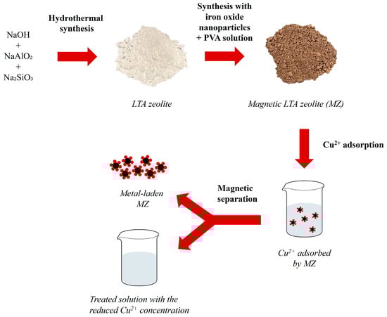
Figure 1.
Graphical representation of the experimental procedure carried out in this research showing the first step of LTA zeolite synthesis from analytical grade chemicals as a source of Al and Si, and the obtained dry LTA zeolite powder after hydrothermal synthesis. Then, after mixing and heating zeolite with iron oxide nanoparticles and PVA solution, magnetic LTA zeolite (MZ) was obtained. Dried MZ was used in Cu2+ adsorption from an aqueous solution and then extracted from the treated solution via magnetic separation.
2.1. LTA Zeolite Synthesis
Linde Type A (LTA) zeolite (Si(50), Al(50)) was synthesized using the method described in Verified Syntheses of Zeolitic Materials [63]. For the synthesis, sodium hydroxide (Thermo Fisher Scientific Inc., Waltham, MA, USA, >99% NaOH), sodium aluminate (Fisher Scientific, NaO2:Al2O3:3H2O), sodium metasilicate (Thermo Fisher Scientific Inc., Waltham, MA, USA, Na2SiO3:5H2O) and reverse osmosis (RO) water were used.
First, ~0.72 g of sodium hydroxide was dissolved in 80 mL of RO water and then divided into two equal volumes in polypropylene bottles. After that, one-half of the solution was gently mixed with ~8.26 g of sodium aluminate in a capped polypropylene bottle until fully dissolved. Next, the remaining half of the sodium hydroxide solution was mixed with ~15.48 g of sodium metasilicate and mixed in a sealed bottle until fully dissolved. Subsequently, the silicate solution was quickly poured into the aluminate solution, forming a thick gel. The bottle was then shaken until the gel homogenized. Afterward, the sealed bottle was placed into an oven for 4 h at 99 ± 1 °C. In the next step, the bottle was extracted from the oven and allowed to cool to room temperature, and then the contents of the bottle were washed out using RO water and filtered using a pressure filter (OFI Testing Equipment, Inc., Houston, TX, USA). The wet solid product was dried overnight at ~60°C, and then the dried product was weighed using a precision balance (Mettler AJ100 Analytical balance, Gemini, Apeldoorn, The Netherlands). A graphical representation of the described synthesis process can be seen in Figure 2. To investigate the synthesized material crystal structure, it was analyzed using X-ray diffraction (XRD), and the obtained pattern or diffractogram was compared with the data from the Crystallography Open Database (COD).
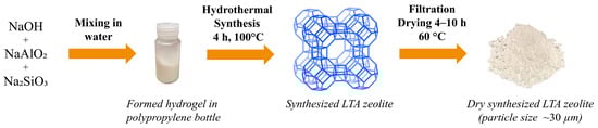
Figure 2.
Graphical representation of the process of LTA zeolite synthesis used in this work. The image of the LTA zeolite framework (view along [100] direction) is adapted from the website of the International Zeolite Association (IZA) [64]. Pictures of hydrogel in a polypropylene bottle and dry synthesized LTA zeolite were taken during the experiments.
2.2. Iron Oxide Nanoparticles: LTA Zeolite Composite
To synthesize magnetic zeolite (MZ), the LTA zeolite synthesized in the previous section was mixed with iron oxide nanopowder and a novel high-temperature colloidal polyvinyl alcohol (PVA) solution.
For the preparation of the PVA solution, a glass flask was used to mix 1 g of boric acid (crystalline, Thermo Fisher Scientific Inc., Waltham, MA, USA) and 0.1 g of copper (II) sulfate (anhydrous, Sigma-Aldrich) in 40 mL of RO water. This catalytic mixture was stirred using a magnetic stirrer for 15 min at 70 °C until the complete dissolution of both polymerization catalysts. Subsequently, 300 mL of tetrahydrofurfuryl acid (THFA) (Sigma-Aldrich, Burlington, VT, USA) and 40 g of polyvinyl acetate (Sigma-Aldrich, USA) were added into the flask in an IKA RV 10 rotary evaporator (IKA, Wilmington, NC, USA) for 3 h at 180 rpm, 70 °C, and 0.95 bar. Consequently, all traces of water were removed from the solution using a vacuum oven (VWR, Radnor, PA, USA) at 90 °C for 2 h. The colloidal PVA solution was cooled to room temperature, for use in the subsequent magnetic zeolite synthesis.
To synthesize the magnetic zeolite, 10 g of LTA zeolite was mixed with a certain amount (0.1 g, 0.5 g, 1 g, and 2 g) of 50–100 nm iron oxide nanopowder (Iron (II, III) oxide, Sigma-Aldrich, USA) followed by the addition of 20 mL of colloidal PVA solution. The solution was then sonicated using Sonics Vibra-Cell VC 50 (Sonics & Materials Inc., Newtown, CT, USA) for 15 min in a glass beaker, after which reverse osmosis (RO) water was added to form a hydrogel. The hydrogel was then dried in a muffle furnace for 2 h at 160 °C in a polytetrafluoroethylene (PTFE) container to bond iron oxide nanoparticles and CFAZ together through PVA cross-linking. After that, the obtained material was cooled to room temperature and then transferred into a ceramic container and heated in the air in the muffle furnace for 2 h at 400 °C to cure and carbonize the PVA cross-linking. The final obtained material was then cooled to room temperature and milled to a very fine powder using a monomill (Pulverisette, 6 planetary monomill, Fritsch, Idar-Oberstein, Germany) for 5 min set at 500 rpm.
2.3. Adsorption Experiments
Synthetic copper solutions with an initial Cu2+ ion concentration of 300 mg/L were prepared using copper (II) nitrate trihydrate, 99% (Thermo Fisher Scientific Inc., Waltham, MA, USA), by preparing stock solutions that were then diluted using RO water. Unless stated otherwise, all adsorption experiments were conducted in 200 mL glass beakers positioned on an orbital shaker (New Brunswick Scientific Co., Edison, NJ, USA) and covered with parafilm.
For adsorption experiments, magnetic zeolites with iron oxide nanoparticle loadings of 0.1 g (MZ0.1), 0.5 g (MZ0.5), and 1g (MZ1) were used. Thus, 0.1 g MZ was added in 100 mL of synthetic copper solution, and then ~5 mL samples were taken periodically from the solution using a syringe and filtered using a 0.1 μm filter (Sigma-Aldrich, Burlington, VT, USA), stopping the adsorption in the sample. The Cu2+ concentration in the filtered samples was measured using an X-ray fluorescence (XRF) analyzer, the Epsilon 1 (Malvern Panalytical, Malvern, UK). The graphical workflow of the adsorption process is presented in Figure 3.
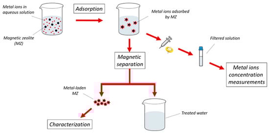
Figure 3.
Graphical representation of the adsorption and magnetic separation process used in this study.
All experiments were conducted at room temperature without temperature control and at pH 6. The pH of each solution was measured before and after adsorption, and no changes were observed. Each experiment was conducted in triplicate, and a control experiment with no addition of zeolite in the solution was performed to confirm that there was no precipitation or change in metal concentration without zeolite in the system.
2.4. Magnetic Separation Technology for the Extraction of Magnetic Zeolite
To separate the magnetic phase from the nonmagnetic and to confirm that the synthesized material can be removed from a slurry, a jaw-type wet high-intensity magnetic separator (WHIMS) (Bunting Redditch, Redditch, UK) was used. The working parameters of WHIMS in this study were 12 A, 184 V, and 1.4 T. After the slurry was slowly poured into the WHIMS funnel, nonmagnetic particles passed through, while magnetic particles remained inside the metal matrix. Nonmagnetic particles were collected in a container under WHIMS, and magnetic particles were washed out after WHIMS was turned off, and magnetic force was not applied. The described process is summarized in a schematic diagram in Figure 4.
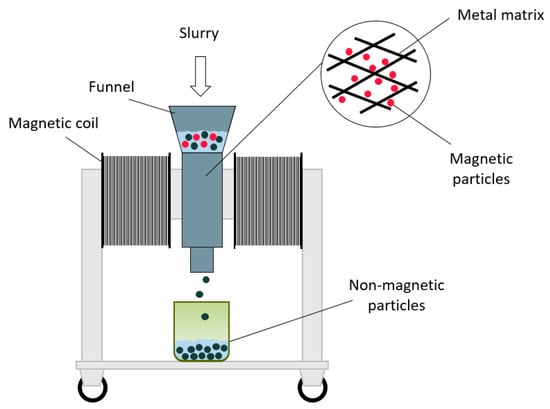
Figure 4.
Schematic diagram of high-intensity electromagnetic separator (WHIMS) used for the extraction of magnetic zeolite.
2.5. Characterization Techniques
X-ray diffraction (XRD) patterns were recorded using Bruker D2 phaser (Bruker, Karlsruhe, Germany) with the LYNXEYE XE-T, Cu, Kα, and (λ = 1.5418 Å) X-ray source and operating conditions of 30 kV and 10 mA. The diffraction angle (2θ) was measured in the range 5–70°. Diffraction patterns were analyzed using DIFFRAC.EVA software (Bruker, Billerica, MA, USA).
The X-ray photoelectron spectrometer (XPS) used in this study was a Thermo Scientific K-Alpha monochromatic X-ray photoelectron spectrometer (Thermo Fisher Scientific Inc., Waltham, MA, USA). It was equipped with an Al Kα X-ray source (1486.6 eV, 0.834 nm), an ultrahigh vacuum chamber (10−9 Torr), and a microfocused monochromator. The analysis consisted of an elemental survey from 0 to 1350 eV and high-resolution scans with a pass energy of 1 and 0.1 eV, respectively. The analyses were conducted on 3 target points for each sample using a spot size of 400 μm. Zeolite samples were dried overnight in an oven at ∼60 °C and then were kept in a desiccator prior to analysis. Experimental results were analyzed using Avantage V6 Data System software (Thermo Fisher Scientific Inc., Waltham, MA, USA).
Scanning electron microscopy (SEM) was conducted using a SU3500 SEM (Hitachi, Tokyo, Japan) equipped with an 80 mm2 X-MaxN Silicon Drift energy dispersive spectrometer (EDS) detector (Oxford Instruments, Abingdon, UK). The collected data were analyzed using the AZtec software (Oxford Instruments, UK).
Specific surface area was measured using the nitrogen Brunauer–Emmett–Teller (N2-BET) technique on a TriStar II Plus surface area and porosity analyzer (Micromeritics, Norcross, GA, USA).
Particle size analysis (PSA) was performed using an LA-920 particle size analyzer (Horiba, Kyoto, Japan).
A Lakeshore 8600 Series (Lake Shore Cryotronics, Inc., Westerville, OH, USA) vibrating-sample magnetometer (VSM) was used to measure the magnetic properties of pure zeolite A, and the synthesized composite materials with iron oxide nanoparticle loadings of 1 g (MZ1) and 2 g (MZ2). Powder samples were loaded in Kel-F powder sample holders and measured at room temperature from 0 to +1.9 T, +1.9 to −1.9 T, and −1.9 T to +1.9T.
3. Results
Unless stated otherwise, the synthesized materials will be referred to as follows in the Section 3 of this paper, with the aim of simplifying their names: pure synthesized LTA zeolite—pure zeolite; MZ0.1, MZ0.5, MZ1, and MZ2—magnetic zeolite with the mixed ratio of 10 g of pure zeolite and 0.1 g, 0.5 g, 1 g, and 2g of iron oxide nanoparticles, respectively.
3.1. Characterization of Synthesized Zeolites
The results of surface area and particle size measurements are presented in Table 2.
Table 2.
Surface characterization of synthesized zeolites.
The synthesized zeolites were characterized using XRD. The acquired diffractograms were compared with each other and with a reference comprising LTA zeolite (Na12Al12Si12O48) [65] and iron oxide. It can be seen from Figure 5 that the pure zeolite diffractogram has the same peak positions and similar intensities as the reference LTA zeolite. Furthermore, it can be seen that MZ0.1–MZ1 have peaks corresponding to the positions of iron oxide reference peaks at 18.31° and 35.47° (2θ). Additionally, it is observed that, with an increase in the number of added iron oxide nanoparticles to the synthesis process, the peak intensities also increase, i.e., MZ1 has higher peaks than MZ0.5 and MZ0.1.
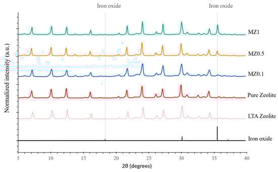
Figure 5.
XRD diffractograms of synthesized zeolites (pure zeolite and MZ0.1–MZ1) compared with reference XRD patterns of LTA zeolite and iron oxide.
The degree of crystallinity (DOC) of the synthesized zeolites was calculated from the obtained XRD data using the following equation [66,67]:
The results were calculated as 39.7% for pure synthesized LTA zeolite, and 35.6%, 38.6%, and 39% for MZ0.1, MZ0.5, and MZ1, respectively.
Figure 6 shows the SEM-EDS scans of pure synthetic zeolite A, revealing that it mainly consists of Si, Al, and Na.
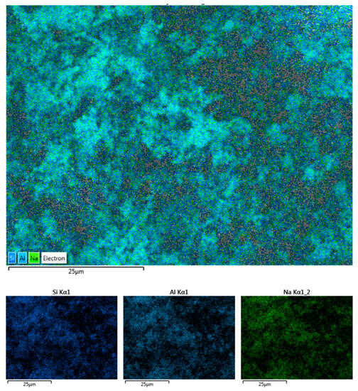
Figure 6.
EDS image of synthesized zeolite A indicating the presence of Si, Al, and Na in the sample.
The results of the VSM characterization of pure zeolite compared with synthesized magnetic zeolites MZ1 and MZ2 and to the iron oxide nanoparticles are shown in Figure 7. The pure zeolite is slightly diamagnetic and appears as a flat line in Figure 7a; the diamagnetic trend can be seen more clearly in Figure 7b. Figure 7c shows a very small hysteresis for the iron oxide nanoparticles, MZ1, and MZ2. The coercivity of the iron oxide nanoparticles was −4.5 kA m−1, and the coercivities for MZ1 and MZ2 were −4.7 and −5.0 kA m−1, respectively. These results indicate that the iron oxide nanoparticles exhibit superparamagnetic properties, and as the slightly diamagnetic zeolite is combined with the iron oxide nanoparticles in increasing quantities, the saturation magnetization decreases. The saturation magnetization is highest for the pure iron oxide nanoparticles and lower for MZ2 andMZ1 with the order corresponding to the iron oxide nanoparticle content.
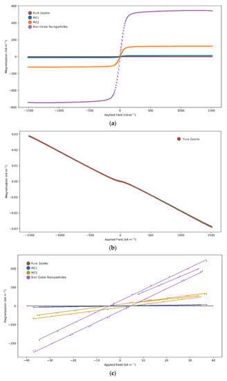
Figure 7.
Vibrating sample magnetometry comparison: (a) pure zeolite, MZ1, MZ2, and iron oxide nanoparticles; (b) pure zeolite with scaled Y-axis highlighting slightly diamagnetic properties; (c) all samples, zoomed in between −50 and +50 kA m−1, showing very slight hysteresis.
3.2. Copper Adsorption Experiments
During adsorption experiments, it is expected that Cu concentration in the prepared solution will gradually decrease over time, as the zeolite adsorbs metal ions. Eventually, the concentration should reach equilibrium, where it no longer changes over time. The equilibrium concentration is used to calculate the adsorbed fraction qe (mg/g), which is defined as follows:
where C0 and Ce are the initial and equilibrium metal concentrations in the solution (mg/L), V is the volume (L), and ms is the amount of added zeolite in the system (g).
Figure 8 indicates that there were notable differences in the kinetics or equilibrium concentrations across the studied zeolites. For pure zeolite, the equilibrium concentration of Cu2+ ions was found to be 38 ppm. When comparing magnetic zeolites MZ0.1, MZ0.5, and MZ1, the adsorption capacity decreased as the proportion of iron oxide nanoparticles increased. Thus, MZ0.1 equilibrated at 149 ppm, MZ0.5 at a similar concentration of 147 ppm, and MZ1 at a lower concentration of 130 ppm. Therefore, it can be concluded that the addition of further iron oxide nanoparticles did not continue to affect adsorption performance and speed. The results mentioned above are provided with a 95% confidence interval. A more evident comparison of the obtained results can be seen in Figure 9.
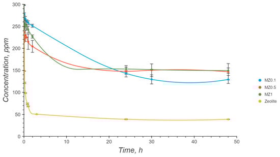
Figure 8.
Adsorption of Cu2+ ions by different synthesized zeolites.
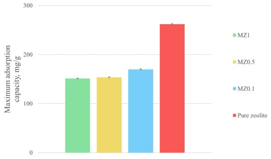
Figure 9.
Comparison of adsorption capacities of different zeolites used in this study for Cu2+ ions.
Based on these adsorption experiments and the previously measured surface areas of the used zeolites, the maximum adsorption capacity was calculated for all the investigated zeolites in mg/g and mg/m2. The results are summarized in Table 3.
Table 3.
Calculated maximum adsorption capacities for Cu2+ ions for synthesized zeolites used in this study.
To better understand the underlying process of Cu removal from water, adsorption models were investigated. The Langmuir and Freundlich adsorption models were fit to the obtained experimental data and adsorption parameters.
The Langmuir model assumes that adsorption occurs through the formation of a monolayer of adsorbate molecules on the homogeneous surface of the adsorbent. It can be described using the following equation:
where Qsat is the monolayer adsorption capacity, mg/g; KL is the Langmuir constant related to the adsorption capacity, which obeys the free adsorption energy, L/mg. The linear form of Equation (3) is presented as follows:
When adsorption involves the formation of multiple layers of adsorbate molecules on a heterogeneous surface of the adsorbent, the process can be described using the Freundlich adsorption model which is mathematically described as follows:
where Kf is the Freundlich constant related to the adsorption capacity, L/g; and n is the adsorption intensity, describing the heterogeneity of the adsorbate sites.
Figure 10, Figure 11, Figure 12 and Figure 13 show the adsorption isotherms’ fit to the Langmuir nonlinear, Langmuir linear, and Freundlich models for Cu2+ adsorption on all the synthesized zeolites.
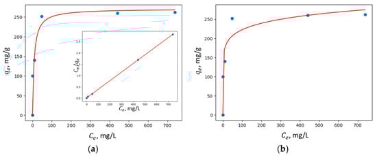
Figure 10.
Adsorption isotherms of Cu2+ adsorption on pure zeolite fit to (a) Langmuir nonlinear and linear models and (b) the Freundlich model.
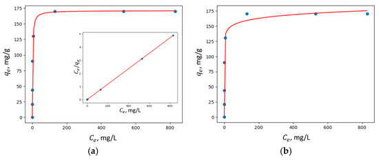
Figure 11.
Adsorption isotherms of Cu2+ adsorption on MZ0.1 fit to (a) Langmuir nonlinear and linear models and (b) the Freundlich model.
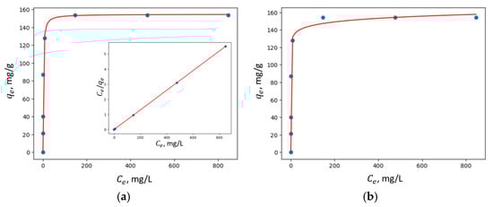
Figure 12.
Adsorption isotherms of Cu2+ adsorption on MZ0.5 fit to (a) Langmuir nonlinear and linear models and (b) the Freundlich model.
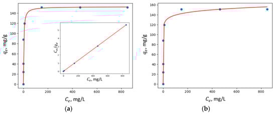
Figure 13.
Adsorption isotherms of Cu2+ adsorption on MZ1 fit to (a) Langmuir nonlinear and linear models and (b) the Freundlich model.
The summary of the applied models and the results obtained for their parameters, including the corresponding values for the correlation coefficients R2, are provided in Table 4.
Table 4.
The results from the thermodynamic model studies of the experimental isotherms for adsorption of Cu2+ ions.
In all the studied zeolites, the Langmuir linear model exhibited a higher correlation coefficient R2, suggesting that adsorption predominantly occurs via the formation of a monolayer of adsorbate molecules on the homogeneous surface of the investigated adsorbents.
3.3. Characterization of Zeolites after Adsorption
High-resolution XPS survey spectra were collected and compared for zeolite samples before and after adsorption and compared with a baseline of pure zeolite, the results of which are presented in Figure 14. The analysis confirmed the presence of Cu ions on the surface of MZ samples tested after adsorption experiments. Furthermore, Fe peaks were detected for some of the MZ zeolites, even though the intensity of these peaks was low. Thus, Figure 14 shows the peaks for Cu 2p3 at 935.28 eV, Na 1s at 1072.85 eV, and Fe 2p at 711.36 eV. Moreover, it is evident that, before adsorption, Na peaks are present in all zeolite samples. However, after adsorption, and reaching the maximum adsorption capacity, Cu peaks emerge, while Na peaks vanish. These findings suggest an ion exchange mechanism for Cu adsorption by the investigated zeolites.
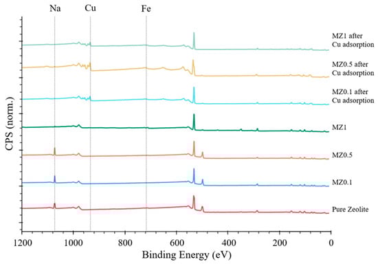
Figure 14.
XPS spectra comparison of pure zeolite and MZ0.1–MZ1 before and after Cu2+ ion adsorption.
To further investigate the magnetic zeolites and their adsorption performance for Cu ions, SEM-EDS experiments were performed. SEM images were taken at 5.00 k magnification and a low voltage of 10.0 kV of pure zeolite and MZ1. The results presented in Figure 15 indicate that the synthesized zeolites used in this study have cubic morphology typical for LTA zeolites.
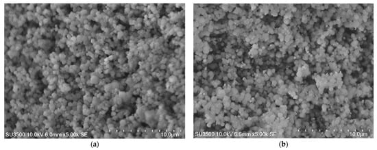
Figure 15.
SEM images: (a) pure zeolite; (b) MZ 10:1.
Figure 16 shows the comparison of SEM-EDS images of MZ before and after Cu adsorption. As can be seen, the image for the MZ sample before adsorption indicates the presence of iron (represented by red areas). Furthermore, after Cu adsorption, both Fe and Cu are present. This result further confirms that magnetic synthesized zeolites adsorbed Cu from the investigated solutions. Similar SEM-EDS scans were performed on MZ0.1 and MZ0.5 samples and showed the same results, indicating the presence of both Cu and Fe after adsorption experiments.
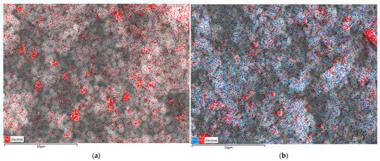
Figure 16.
EDS of MZ1: (a) before adsorption; (b) after adsorption. Red areas correspond to Fe and blue areas correspond to Cu in the analyzed samples.
To confirm these results, EDS spectra were obtained using AZtec software. The results are presented in Figure 17, indicating the presence of Cu ions in MZ samples after the adsorption process. Furthermore, Na peaks were present in MZ0.1–MZ1 but were no longer present in the same samples after Cu adsorption, suggesting an ion exchange mechanism. Additionally, in MZ0.5 and MZ1, an Fe peak was observed before and after adsorption. These results correspond well with the previous experimental data obtained with the different characterization techniques used in this work.
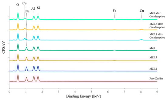
Figure 17.
EDS results comparing the MZ samples used in this study before and after adsorption of Cu2+ ions and baseline of pure synthetic LTA zeolite (red line).
3.4. Extraction of Magnetic Zeolite from Treated Water Using WHIMS
To remove the magnetic zeolite from the solution after the adsorption process equilibrated, WHIMS was used. The treated solution, containing the magnetic zeolite, was introduced into the WHIMS funnel, where the magnetic zeolite became trapped within the metal matrix of WHIMS, while the rest passed through and was collected in a clean beaker. Figure 18 shows a photo of the treated solution after adsorption with the presence of magnetic zeolite that caused a reddish color, shown on the left, and the purified transparent solution devoid of zeolite particles on the right. These results indicate that only one cycle of magnetic zeolite extraction is needed for the used amount of adsorbent and solution.
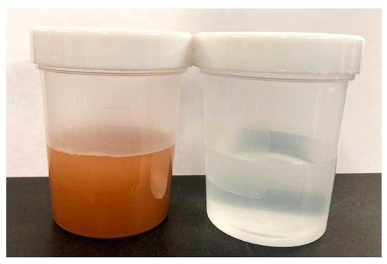
Figure 18.
Treated solution with magnetic zeolite particles (left bottle) and after extraction of magnetic zeolite using WHIMS (right bottle).
4. Conclusions
This study aimed to address the challenge of separating fine-sized zeolite particles from treated water by introducing a novel synthesis method of magnetic zeolite utilizing colloidal PVA solution to bind iron oxide nanoparticles and LTA zeolite. The characterization results of XRD, XPS, and SEM-EDS confirmed the effectiveness of this synthesis method.
Further experiments were focused on the influence of varying iron oxide nanoparticle loadings in the synthesis process on the obtained zeolites and their performance in Cu adsorption. Thus, 10:1, 10:0.5, and 10:0.1 zeolite–iron oxide nanoparticles ratios were investigated in batch adsorption experiments. Although pure zeolite was more effective for Cu removal from aqueous solutions (maximum adsorption capacity was found to be 262 mg/g), all synthesized magnetic zeolites were also found to be effective in removing Cu ions (151 mg/g, 15 mg/g, and 170 mg/g for 10:1, 10:0.5, and 10:0.1 loading, respectively). Furthermore, the findings indicate minimal fluctuation in the adsorption capacity of the synthesized magnetic zeolites. Therefore, adding a smaller number of iron oxide nanoparticles in the synthesis process would be more practical for further industrial applications and will not significantly affect the adsorption performance of magnetic zeolite.
Moreover, the magnetic properties of these zeolites enabled their removal using magnetic separation. This study demonstrates that fine particles of magnetic zeolite can be efficiently extracted from the treated solution using a single cycle of wet high-intensity magnetic separation. Moving forward, it would be valuable to perform further experiments focusing on the regeneration of the extracted zeolite and its potential for reuse in multiple adsorption cycles. These investigations would contribute to a deeper understanding of the practical application, sustainability, and further use of magnetic zeolites in heavy metal removal from water.
Author Contributions
Conceptualization, K.E.W., N.A.R. and O.K.; methodology, K.E.W., O.K., P.O. and S.B.; software, S.B. and R.S.; validation, S.B., W.H. and O.K.; formal analysis, S.B., W.H. and R.S.; investigation, S.B., W.H., R.S. and O.B.; resources, K.E.W. and P.O.; data curation, S.B.; writing—original draft preparation, S.B.; writing—review and editing, K.E.W. and P.O.; visualization, S.B. and R.S.; supervision, K.E.W., O.K. and P.O.; project administration, K.E.W.; funding acquisition, K.E.W. All authors have read and agreed to the published version of the manuscript.
Funding
The authors are grateful for the financial support from the Natural Sciences and Engineering Research Council of Canada (NSERC), Teck Resources Limited, COREM, SGS Canada Inc., and Flottec, under the Collaborative Research and Development Grants Program (grant number CRDPJ-531957-18). The McGill Engineering Doctoral Award (MEDA) from the Faculty of Engineering at McGill University is also acknowledged for a scholarship awarded to S. Buzukashvili.
Data Availability Statement
Not applicable.
Conflicts of Interest
The authors declare no conflict of interest.
References
- Barakat, M.A. New trends in removing heavy metals from industrial wastewater. Arab. J. Chem. 2011, 4, 361–377. [Google Scholar] [CrossRef]
- Trakal, L.; Šigut, R.; Šillerová, H.; Faturíková, D.; Komárek, M. Copper removal from aqueous solution using biochar: Effect of chemical activation. Arab. J. Chem. 2014, 7, 43–52. [Google Scholar] [CrossRef]
- Ruyters, S.; Salaets, P.; Oorts, K.; Smolders, E. Copper toxicity in soils under established vineyards in Europe: A survey. Sci. Total Environ. 2013, 443, 470–477. [Google Scholar] [CrossRef] [PubMed]
- Shrestha, R.; Ban, S.; Devkota, S.; Sharma, S.; Joshi, R.; Tiwari, A.P.; Kim, H.Y.; Joshi, M.K. Technological trends in heavy metals removal from industrial wastewater: A review. J. Environ. Chem. Eng. 2021, 9, 105688. [Google Scholar] [CrossRef]
- Ab Hamid, N.H.; bin Mohd Tahir, M.I.; Chowdhury, A.; Nordin, A.H.; Alshaikh, A.A.; Suid, M.A.; Nazaruddin, N.; Nozaizeli, N.D.; Sharma, S.; Rushdan, A.I. The Current State-Of-Art of Copper Removal from Wastewater: A Review. Water 2022, 14, 3086. [Google Scholar] [CrossRef]
- Yin, Z.; Zhu, L.; Mo, F.; Li, S.; Hu, D.; Chu, R.; Liu, C.; Hu, C. Preparation of biochar grafted with amino-riched dendrimer by carbonization, magnetization and functional modification for enhanced copper removal. J. Taiwan Inst. Chem. Eng. 2021, 121, 349–359. [Google Scholar] [CrossRef]
- Al-Saydeh, S.A.; El-Naas, M.H.; Zaidi, S.J. Copper removal from industrial wastewater: A comprehensive review. J. Ind. Eng. Chem. 2017, 56, 35–44. [Google Scholar] [CrossRef]
- Gong, J.-L.; Wang, X.-Y.; Zeng, G.-M.; Chen, L.; Deng, J.-H.; Zhang, X.-R.; Niu, Q.-Y. Copper (II) removal by pectin–iron oxide magnetic nanocomposite adsorbent. Chem. Eng. J. 2012, 185–186, 100–107. [Google Scholar] [CrossRef]
- Wang, S.; Peng, Y. Natural zeolites as effective adsorbents in water and wastewater treatment. Chem. Eng. J. 2010, 156, 11–24. [Google Scholar] [CrossRef]
- Silva, M.; Lecus, A.; Gajdardziska-Josifovska, M.; Schofield, D.; Virnoche, M.; Chang, J.; Chen, J.; Garman, D. Graphene-oxide loading on natural zeolite particles for enhancement of adsorption properties. RSC Adv. 2020, 10, 4589–4597. [Google Scholar] [CrossRef]
- Čejka, J.; Millini, R.; Opanasenko, M.; Serrano, D.P.; Roth, W.J. Advances and challenges in zeolite synthesis and catalysis. Catal. Today 2020, 345, 2–13. [Google Scholar] [CrossRef]
- Roque-Malherbe, R. Chapter 12—Applications of Natural Zeolites in Pollution Abatement and Industry. In Handbook of Surfaces and Interfaces of Materials; Nalwa, H.S., Ed.; Academic Press: Burlington, ON, Canada, 2001; pp. 495–522. [Google Scholar]
- Pérez-Botella, E.; Valencia, S.; Rey, F. Zeolites in Adsorption Processes: State of the Art and Future Prospects. Chem. Rev. 2022, 122, 17647–17695. [Google Scholar] [CrossRef] [PubMed]
- Ernst, S. Zeolites and Catalysis. Synthesis, Reactions and Applications. Edited by Jiri Cejka, Avelino Corma and Stacey Zones. Angew. Chem. Int. Ed. 2011, 50, 5425–5426. [Google Scholar] [CrossRef]
- Speight, J.G. Heavy Oil Recovery and Upgrading; Gulf Professional Publishing: Houston, TX, USA, 2019. [Google Scholar]
- Kühl, G.H. Modification of Zeolites. In Catalysis and Zeolites: Fundamentals and Applications; Weitkamp, J., Puppe, L., Eds.; Springer Berlin Heidelberg: Berlin/Heidelberg, Germany, 1999; pp. 81–197. [Google Scholar]
- Shi, J.; Yang, Z.; Dai, H.; Lu, X.; Peng, L.; Tan, X.; Shi, L.; Fahim, R. Preparation and application of modified zeolites as adsorbents in wastewater treatment. Water Sci. Technol. 2018, 2017, 621–635. [Google Scholar] [CrossRef]
- Mallette, A.J.; Seo, S.; Rimer, J.D. Synthesis strategies and design principles for nanosized and hierarchical zeolites. Nat. Synth. 2022, 1, 521–534. [Google Scholar] [CrossRef]
- Xu, H.; Wu, P. New progress in zeolite synthesis and catalysis. Natl. Sci. Rev. 2022, 9, nwac045. [Google Scholar] [CrossRef] [PubMed]
- Buzukashvili, S.; Sommerville, R.; Rowson, N.A.; Waters, K.E. An overview of zeolites synthesised from coal fly ash and their potential for extracting heavy metals from industrial wastewater. Can. Metall. Q. 2023, 1–23. [Google Scholar] [CrossRef]
- Misaelides, P. Application of natural zeolites in environmental remediation: A short review. Microporous Mesoporous Mater. 2011, 144, 15–18. [Google Scholar] [CrossRef]
- Moliner, M. Design of Zeolites with Specific Architectures Using Self-Assembled Aromatic Organic Structure Directing Agents. Top. Catal. 2015, 58, 502–512. [Google Scholar] [CrossRef]
- International Zeolite Association (IZA). Available online: http://www.iza-online.org/synthesis/Recipes/Linde%20Type%20A.html (accessed on 19 May 2023).
- Drioli, E.; Giorno, L. Encyclopedia of Membranes; Springer: Berlin/Heidelberg, Germany, 2016. [Google Scholar]
- Sherman, J.D. Synthetic zeolites and other microporous oxide molecular sieves. Proc. Natl. Acad. Sci. USA 1999, 96, 3471–3478. [Google Scholar] [CrossRef]
- Yu, J. Synthesis of zeolites. Introd. Zeolite Sci. Pract. 2007, 168, 39. [Google Scholar]
- Matis, K.A.; Zouboulis, A.I.; Gallios, G.P.; Erwe, T.; Blöcher, C. Application of flotation for the separation of metal-loaded zeolites. Chemosphere 2004, 55, 65–72. [Google Scholar] [CrossRef] [PubMed]
- Castro, C.J.; Shyu, H.Y.; Xaba, L.; Bair, R.; Yeh, D.H. Performance and onsite regeneration of natural zeolite for ammonium removal in a field-scale non-sewered sanitation system. Sci. Total Environ. 2021, 776, 145938. [Google Scholar] [CrossRef]
- Younas, F.; Mustafa, A.; Farooqi, Z.U.; Wang, X.; Younas, S.; Mohy-Ud-Din, W.; Ashir Hameed, M.; Mohsin Abrar, M.; Maitlo, A.A.; Noreen, S.; et al. Current and Emerging Adsorbent Technologies for Wastewater Treatment: Trends, Limitations, and Environmental Implications. Water 2021, 13, 215. [Google Scholar] [CrossRef]
- Maharana, M.; Sen, S. Magnetic zeolite: A green reusable adsorbent in wastewater treatment. Mater. Today Proc. 2021, 47, 1490–1495. [Google Scholar] [CrossRef]
- Loiola, A.R.; Bessa, R.A.; Oliveira, C.P.; Freitas, A.D.L.; Soares, S.A.; Bohn, F.; Pergher, S.B.C. Magnetic zeolite composites: Classification, synthesis routes, and technological applications. J. Magn. Magn. Mater. 2022, 560, 169651. [Google Scholar] [CrossRef]
- Sharma, A.; Mangla, D.; Shehnaz; Chaudhry, S.A. Recent advances in magnetic composites as adsorbents for wastewater remediation. J. Environ. Manag. 2022, 306, 114483. [Google Scholar] [CrossRef]
- Ambashta, R.D.; Sillanpää, M. Water purification using magnetic assistance: A review. J. Hazard. Mater. 2010, 180, 38–49. [Google Scholar] [CrossRef]
- Mehta, D.; Mazumdar, S.; Singh, S.K. Magnetic adsorbents for the treatment of water/wastewater—A review. J. Water Process Eng. 2015, 7, 244–265. [Google Scholar] [CrossRef]
- Ali, I.; Peng, C.; Naz, I.; Amjed, M.A. Water Purification Using Magnetic Nanomaterials: An Overview. In Magnetic Nanostructures: Environmental and Agricultural Applications; Springer: Berlin/Heidelberg, Germany, 2019; pp. 161–179. [Google Scholar]
- Philippova, O.; Barabanova, A.; Molchanov, V.; Khokhlov, A. Magnetic polymer beads: Recent trends and developments in synthetic design and applications. Eur. Polym. J. 2011, 47, 542–559. [Google Scholar] [CrossRef]
- Kharissova, O.V.; Dias, H.V.R.; Kharisov, B.I. Magnetic adsorbents based on micro- and nano-structured materials. RSC Adv. 2015, 5, 6695–6719. [Google Scholar] [CrossRef]
- Li, N.; Li, Z.; Zhang, L.; Shi, H.; Li, J.; Zhang, J.; Zhang, Z.; Dang, F. One-step fabrication of bifunctional self-assembled oligopeptides anchored magnetic carbon nanoparticles and their application in copper (II) ions removal from aqueous solutions. J. Hazard. Mater. 2020, 382, 121113. [Google Scholar] [CrossRef] [PubMed]
- Maksoud, M.I.A.; Elgarahy, A.; Farrell, C.; Al-Muhtaseb, A.H.; Rooney, D.; Osman, A. Insight on water remediation application using magnetic nanomaterials and biosorbents. Coord. Chem. Rev. 2019, 403, 213096. [Google Scholar] [CrossRef]
- Iranmanesh, M.; Hulliger, J. Magnetic separation: Its application in mining, waste purification, medicine, biochemistry and chemistry. Chem. Soc. Rev. 2017, 46, 5925–5934. [Google Scholar] [CrossRef]
- Praipipat, P.; Ngamsurach, P.; Roopkhan, N. Zeolite A powder and beads from sugarcane bagasse fly ash modified with iron(III) oxide-hydroxide for lead adsorption. Sci. Rep. 2023, 13, 1873. [Google Scholar] [CrossRef]
- Yuan, M.; Song, C.; Yan, G. Some Research on the Magnetic X Zeolite Composites. Adv. Mater. Res. 2011, 311–313, 2040–2047. [Google Scholar] [CrossRef]
- Yang, Y.; Zhang, P.; Jiang, J.; Dai, Y.; Wu, M.; Pan, Y.; Ni, L. Synthesis and properties of magnetic zeolite with good magnetic stability from fly ash. J. Sol-Gel Sci. Technol. 2018, 87, 408–418. [Google Scholar] [CrossRef]
- Salem Attia, T.M.; Hu, X.L.; Yin, D.Q. Synthesised magnetic nanoparticles coated zeolite (MNCZ) for the removal of arsenic (As) from aqueous solution. J. Exp. Nanosci. 2014, 9, 551–560. [Google Scholar] [CrossRef]
- Peng, Z.-D.; Lin, X.-M.; Zhang, Y.-L.; Hu, Z.; Yang, X.-J.; Chen, C.-Y.; Chen, H.-Y.; Li, Y.-T.; Wang, J.-J. Removal of cadmium from wastewater by magnetic zeolite synthesized from natural, low-grade molybdenum. Sci. Total Environ. 2021, 772, 145355. [Google Scholar] [CrossRef]
- Liu, Y.; Wang, H.; Cui, Y.; Chen, N. Removal of Copper Ions from Wastewater: A Review. Int. J. Environ. Res. Public Health 2023, 20, 3885. [Google Scholar] [CrossRef]
- Boulaiche, W.; Hamdi, B.; Trari, M. Removal of heavy metals by chitin: Equilibrium, kinetic and thermodynamic studies. Appl. Water Sci. 2019, 9, 39. [Google Scholar] [CrossRef]
- Lee, C.-G.; Lee, S.; Park, J.-A.; Park, C.; Lee, S.J.; Kim, S.-B.; An, B.; Yun, S.-T.; Lee, S.-H.; Choi, J.-W. Removal of copper, nickel and chromium mixtures from metal plating wastewater by adsorption with modified carbon foam. Chemosphere 2017, 166, 203–211. [Google Scholar] [CrossRef] [PubMed]
- Gündoğan, R.; Acemioğlu, B.; Alma, M.H. Copper (II) adsorption from aqueous solution by herbaceous peat. J. Colloid Interface Sci. 2004, 269, 303–309. [Google Scholar] [CrossRef] [PubMed]
- Meseldzija, S.; Petrovic, J.; Onjia, A.; Volkov-Husovic, T.; Nesic, A.; Vukelic, N. Utilization of agro-industrial waste for removal of copper ions from aqueous solutions and mining-wastewater. J. Ind. Eng. Chem. 2019, 75, 246–252. [Google Scholar] [CrossRef]
- Doula, M.K.; Dimirkou, A. Use of an iron-overexchanged clinoptilolite for the removal of Cu2+ ions from heavily contaminated drinking water samples. J. Hazard. Mater. 2008, 151, 738–745. [Google Scholar] [CrossRef] [PubMed]
- Ling, C.; Liu, F.-Q.; Long, C.; Chen, T.-P.; Wu, Q.-Y.; Li, A.-M. Synergic removal and sequential recovery of acid black 1 and copper (II) with hyper-crosslinked resin and inside mechanisms. Chem. Eng. J. 2014, 236, 323–331. [Google Scholar] [CrossRef]
- Aydın, H.; Bulut, Y.; Yerlikaya, Ç. Removal of copper (II) from aqueous solution by adsorption onto low-cost adsorbents. J. Environ. Manag. 2008, 87, 37–45. [Google Scholar] [CrossRef] [PubMed]
- Gaballah, I.; Goy, D.; Allain, E.; Kilbertus, G.; Thauront, J. Recovery of copper through decontamination of synthetic solutions using modified barks. Metall. Mater. Trans. B 1997, 28, 13–23. [Google Scholar] [CrossRef]
- Yuwei, C.; Jianlong, W. Preparation and characterization of magnetic chitosan nanoparticles and its application for Cu(II) removal. Chem. Eng. J. 2011, 168, 286–292. [Google Scholar] [CrossRef]
- Albadarin, A.B.; Mo, J.; Glocheux, Y.; Allen, S.; Walker, G.; Mangwandi, C. Preliminary investigation of mixed adsorbents for the removal of copper and methylene blue from aqueous solutions. Chem. Eng. J. 2014, 255, 525–534. [Google Scholar] [CrossRef]
- Alvarez-Ayuso, E.; Garcia-Sanchez, A.; Querol, X. Purification of metal electroplating waste waters using zeolites. Water Res. 2003, 37, 4855–4862. [Google Scholar] [CrossRef] [PubMed]
- He, K.; Chen, Y.; Tang, Z.; Hu, Y. Removal of heavy metal ions from aqueous solution by zeolite synthesized from fly ash. Environ. Sci. Pollut. Res. 2016, 23, 2778–2788. [Google Scholar] [CrossRef]
- Hidayat, E.; Yoshino, T.; Yonemura, S.; Mitoma, Y.; Harada, H. A Carbonized Zeolite/Chitosan Composite as an Adsorbent for Copper (II) and Chromium (VI) Removal from Water. Materials 2023, 16, 2532. [Google Scholar] [CrossRef]
- Gupta, V.K.; Agarwal, S.; Bharti, A.K.; Sadegh, H. Adsorption mechanism of functionalized multi-walled carbon nanotubes for advanced Cu (II) removal. J. Mol. Liq. 2017, 230, 667–673. [Google Scholar] [CrossRef]
- Awual, M.R. A novel facial composite adsorbent for enhanced copper(II) detection and removal from wastewater. Chem. Eng. J. 2015, 266, 368–375. [Google Scholar] [CrossRef]
- Zhang, H.; Li, G.-W.; Feng, W.; Yao, Z.-Y. Cu(II) Adsorption from Aqueous Solution onto Poly(Acrylic Acid/Chestnut Shell Pigment) Hydrogel. Water 2022, 14, 3500. [Google Scholar] [CrossRef]
- Robson, H. Chapter 55—LTA Linde Type A Si(50), Al(50). In Verified Syntheses of Zeolitic Materials; Robson, H., Lillerud, K.P., Eds.; Elsevier Science: Amsterdam, The Netherlands, 2001; pp. 179–181. [Google Scholar]
- International Zeolite Association (IZA). Available online: https://asia.iza-structure.org/IZA-SC/framework.php?STC=LTA (accessed on 19 May 2023).
- Na12Al12Si12O48, Na12-A zeolite (Na12Al12Si12O48 LTA) Crystal Structure: Datasheet from “PAULING FILE Multinaries Edition—2022” in Springer Materials; Material Phases Data System (MPDS): Luzern, Switzerland; National Institute for Materials Science (NIMS): Tsukuba, Japan; Springer-Verlag: Berlin/Heidelberg, Germany, 2023; Available online: https://materials.springer.com/isp/crystallographic/docs/sd_1827398 (accessed on 19 May 2023).
- Aggarwal, S.; Tilley, G. Determination of crystallinity in polyethylene by X-ray diffractometer. J. Polym. Sci. 1955, 18, 17–26. [Google Scholar] [CrossRef]
- Maamoun, I.; Eljamal, O.; Eljamal, R.; Falyouna, O.; Sugihara, Y. Promoting aqueous and transport characteristics of highly reactive nanoscale zero valent iron via different layered hydroxide coatings. Appl. Surf. Sci. 2020, 506, 145018. [Google Scholar] [CrossRef]
Disclaimer/Publisher’s Note: The statements, opinions and data contained in all publications are solely those of the individual author(s) and contributor(s) and not of MDPI and/or the editor(s). MDPI and/or the editor(s) disclaim responsibility for any injury to people or property resulting from any ideas, methods, instructions or products referred to in the content. |
© 2023 by the authors. Licensee MDPI, Basel, Switzerland. This article is an open access article distributed under the terms and conditions of the Creative Commons Attribution (CC BY) license (https://creativecommons.org/licenses/by/4.0/).