Abstract
Additive manufacturing (AM) has provided new possibilities for improving the grain boundary properties of metallic components. However, effectively modifying the microstructure, particularly the grain boundary properties, of laser powder bed fusion (L-PBF) components remains a challenge. Post-processing methods have shown some success in adjusting grain boundary angles, but they have limitations when it comes to complex geometries and internal features. In this study, we propose an innovative in situ heat treatment to control the grain boundary properties of L-PBF components. A model is proposed to predict the thermal cycle at a single point, and it is validated through experiments on 2507 super duplex steel and 316L austenitic steel samples. The results demonstrate that, by applying controlled in situ heat treatment, the dynamic recovery processes can be influenced, and thereby the grain boundary properties of the manufactured parts can be controlled. This proposed method improves our understanding of the impact of in situ heat treatment on grain boundary properties and offers potential for designing and fabricating high-performance L-PBF components. The findings from this study lay the groundwork for the further exploration of grain boundary engineering in metallic components using L-PBF. By leveraging in situ heat treatment, future research can open up new avenues in additive manufacturing, facilitating the production of advanced and high-quality metallic components.
1. Introduction
Additive manufacturing (AM) has revolutionized engineering by enabling the production of customized parts with unique shapes and desired properties [1,2,3]. Laser powder bed fusion (L-PBF) is a widely used AM technique for fabricating metallic components with precise microstructures and desired characteristics [4,5,6]. However, achieving precise control over the microstructure, especially the properties of grain boundaries, in L-PBF components is still a significant challenge [4].
Grain boundaries play a pivotal role in determining the mechanical and physical properties of metallic materials [7]. These interfacial defects act as barriers to dislocation motion, influencing properties such as strength, ductility, and resistance to various forms of degradation, including corrosion and creep [8]. Recent studies have shown that the nature and distribution of grain boundaries can significantly affect the performance of metallic components, especially in advanced manufacturing techniques like L-PBF [9].
Grain boundary engineering (GBE) has emerged as a promising approach to enhancing the mechanical, chemical, and physical properties of materials in L-PBF components [9,10,11,12]. Unlike traditional manufacturing methods and surface laser treatment [13], AM facilitates the modification of the grain boundary properties layer-by-layer, opening up new opportunities for GBE. However, the application of GBE in L-PBF is in its early stages, with limited studies conducted thus far.
One of the primary challenges in advancing the GBE of L-PBF components is the need to understand the relationship between process parameters and microstructural features [14,15]. Currently, our understanding of how these parameters influence grain boundary properties in L-PBF components is limited. Previous research in AM has primarily focused on post-processing techniques such as heat treatment, hot isostatic pressing, and surface finishing to modify the microstructure of L-PBF components [16,17,18,19,20]. Although these techniques have shown promise in altering grain boundary properties, they may not be suitable for complex geometries, highlighting the importance of in-process microstructure control.
In this study, an innovative in situ heat treatment is proposed to control the grain boundary properties of L-PBF components. The main objective is to gain a deeper understanding of the effects of in situ heat treatment on grain boundary properties and explore its potential for enhancing the design and manufacturing of high-performance L-PBF components, specifically using stainless steel and duplex steel. To achieve this, a model has been developed to predict the thermal cycles experienced by material points within components of various shapes. Through experimental validation on 2507 super duplex steel and 316L austenitic steel samples, the robustness of the proposed method is evaluated. The results reveal that controlled in situ heat treatment enables us to influence the dynamic recovery process and effectively control the grain boundary properties of the manufactured parts. These findings contribute to the advancement of grain boundary engineering in L-PBF and offer insights for optimizing the manufacturing process of high-performance components.
2. Materials and Method
2.1. Experimental Approach
- ■
- Materials: In this study, 2507 super duplex steel and 316L austenitic stainless-steel powders, provided by GKN Additive Inc. (Carlsbad, CA, USA), were used for the laser powder bed fusion (L-PBF) process. The powders were spherical in shape and produced using a gas atomization method, ensuring a narrow size distribution and low levels of impurities. The average particle size of the powder was 50 microns, which is considered suitable for the L-PBF process. The components were fabricated using the PANDA L-PBF machine from Open Additive (Beavercreek, OH, USA, equipped with a 500 W IPG Photonics 1070 nm fiber laser (air cooled)).
- ■
- Reheat scan technique: To manage thermal cycling in the L-PBF process, a reheat scan step was implemented after each melting step in the experimental setup. This additional laser scan raised the temperature of the solidified material to a level slightly below its melting point. By adjusting parameters such as the laser power and scan speed, we were able to modify the microstructure and grain boundary properties of the fabricated samples. In the following section, we provide detailed information on the specific parameters used and their influence on the microstructure.
- ■
- Microstructure Analysis: Microstructure analysis was conducted using a Tescan Mira (California, CA, USA) scanning electron microscope (SEM) that was equipped with an Electron Backscatter Diffraction (EBSD) EDAX camera. The SEM was operated at a voltage of 30 kV, a current of 20 nA, and a step size of 1 micron. Prior to EBSD analysis, the samples were prepared by grinding them with 600–1200 grit SiC sandpaper, followed by polishing using 1 μm of diamond suspension and 0.04 μm of colloidal silica.
2.2. Thermal Model
In the L-PBF process, each material point undergoes multiple cycles of heating and cooling during a print due to the laser scan strategy. Figure 1 provides an illustration of the thermal cycling experienced by material point A. When the laser melts the powder, rapid heating occurs, raising the temperature above the metal’s melting point. As the laser moves away, the melt pool cools down quickly. When the laser returns to the nearest point in the next hatch spacing (marked as B), the temperature at point A reaches another peak temperature, this time below the melting point. Subsequent hatch lines do not sufficiently raise the temperature at location A. However, as the laser moves to the next layer above material point A, heat is once again transferred to point A through the powder layer. This scanning process, along with adjacent scans on the top layer, can raise the temperature of point A above half the melting point again. This thermal cycling pattern is a unique characteristic of the L-PBF process and directly affects the microstructure at location A. Thermal cycling can vary from one location to another depending on the laser scan strategy and geometry, indicating that the microstructure is location-dependent. Understanding these thermal cycles facilitates a deeper understanding of the microstructures at different locations within the product.
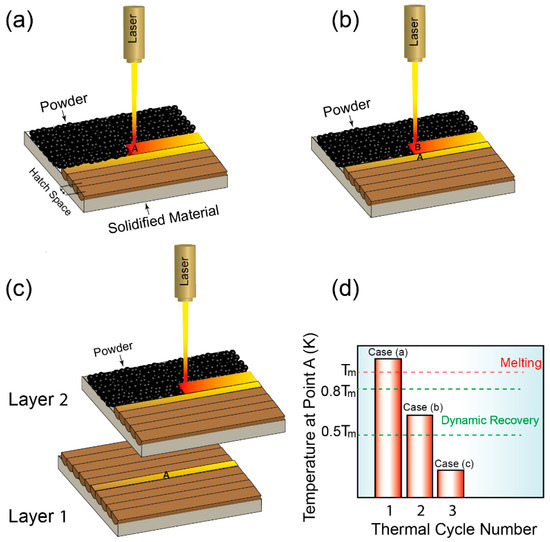
Figure 1.
Schematic depicting thermal cycling at point A in the L-PBF process: (a) Rapid heating when the laser melts the powder. (b) Cooling as the laser departs, with a secondary temperature peak below melting when the laser approaches a neighboring point B. (c) Reintroduction of heat to A as the laser progresses to an upper layer. (d) A graph showcasing the temperature evolution at point A against the number of thermal cycles. This process highlights the influence of the laser scan strategy on the location-specific microstructure variation.
In order to predict the thermal cycle within the hatch or layer thickness, the following equation is used [7].
Here, represents the melt pool peak temperature, G denotes the thermal gradient, and corresponds to the hatch space/layer thickness.
The peak temperature, , can be calculated using the following formula [10]:
where is the boiling temperature, is the maximum heat input before the onset of evaporation, and the heat input can be calculated using Equation (3) [10].
In this equation, A represents the absorptivity, the laser power, the enthalpy at the melting temperature, d the thermal diffusivity, the laser scan speed and D the nominal laser spot size.
Returning to Equation (1), the thermal gradient, G, can be estimated using the following [21]:
where is the laser power and is the laser scan speed.
2.3. Results and Discussion
Previous studies have confirmed the occurrence of dynamic recovery (DRV) during these thermal cycles in the L-PBF process, which takes place between half the melting point and 0.8 times the melting point temperature. DRV leads to the formation of low-angle grain boundaries (LAGBs), while further temperature increases within the range of 0.8 times the melting point to the melting point initiate recrystallization processes, resulting in the formation of high-angle grain boundaries (HAGBs) [7]. To investigate the implications of these phenomena, an in-depth examination of the process parameters in L-PBF was conducted to understand their influence on the occurrence of dynamic recovery and the presence of high-angle grain boundaries in the final parts. The study considered two cases:
- (a)
- Optimization of both the melting and the reheating scans to maximize dynamic recovery.
- (b)
- Utilizing predefined process parameters for the melting scan, selected based on density analysis, followed by the optimization of the reheating scan.
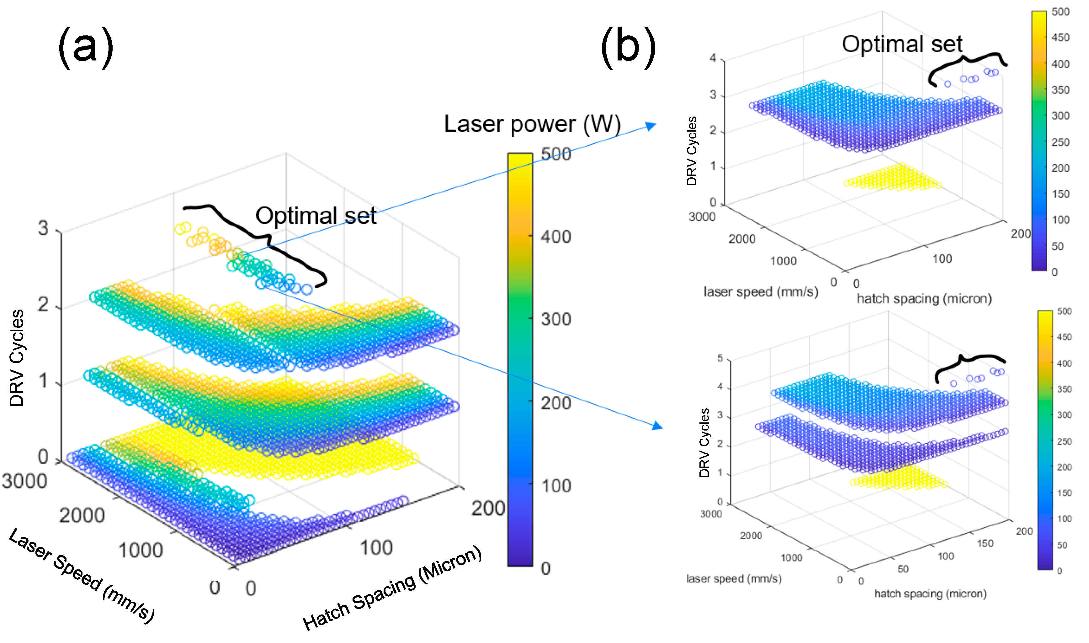
In case (a), a comprehensive series of tests was conducted to identify the optimal balance for a higher rate of dynamic recovery. The study involved a large number of combinations (~25,000 sets) of laser power, speed, and hatch space for the melting track (Figure 2a). To ensure the integrity and quality of the components, the energy input for all combinations was strictly controlled within the range of 65 to 80, calculated using the formula (P = laser power, v = laser scan speed, h = hatch space, and t = layer thickness). This specific range was selected based on previous studies that have shown that such energy density levels can produce fully dense parts. As a result, the tested parameter combinations were directly applicable to practical production conditions, ensuring high-quality outcomes. From extensive testing, a specific set of process parameters (Table 1) was identified, which led to increased dynamic recovery, limited high-angle grain boundaries, and improved the quality of the L-PBF components. The selected parameters underwent further rigorous testing, including a significant number of reheating scan process parameters for each individually optimized melting parameter (Figure 2b). This additional testing aimed to fine-tune the parameters and determine the optimal case. The results of this optimization are presented in Table 1. In case (b), a similar optimization approach was employed, but with a specific focus on the reheating scans (Table 2).
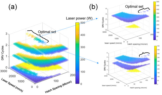
Figure 2.
Process parameter optimization in L-PBF for controlling the occurrence of dynamic recovery steps at a single point. (a) Parameter matrix exploration of laser power, speed, and hatch space in L-PBF for improved dynamic recovery. (b) Refinement of optimized parameters through reheating scan testing in L-PBF for enhanced control of grain boundaries.

Table 1.
Optimized process parameters for melting and reheating scans. Each reheating scan is associated with a corresponding melting scan.
Table 2.
Optimized process parameters for reheating scans, based on predefined process parameters for the melting scan. Parameters for melting scan include power = 310 W, velocity = 1100 mm/s, hatch space = 90 um, and layer thickness = 40 μm.
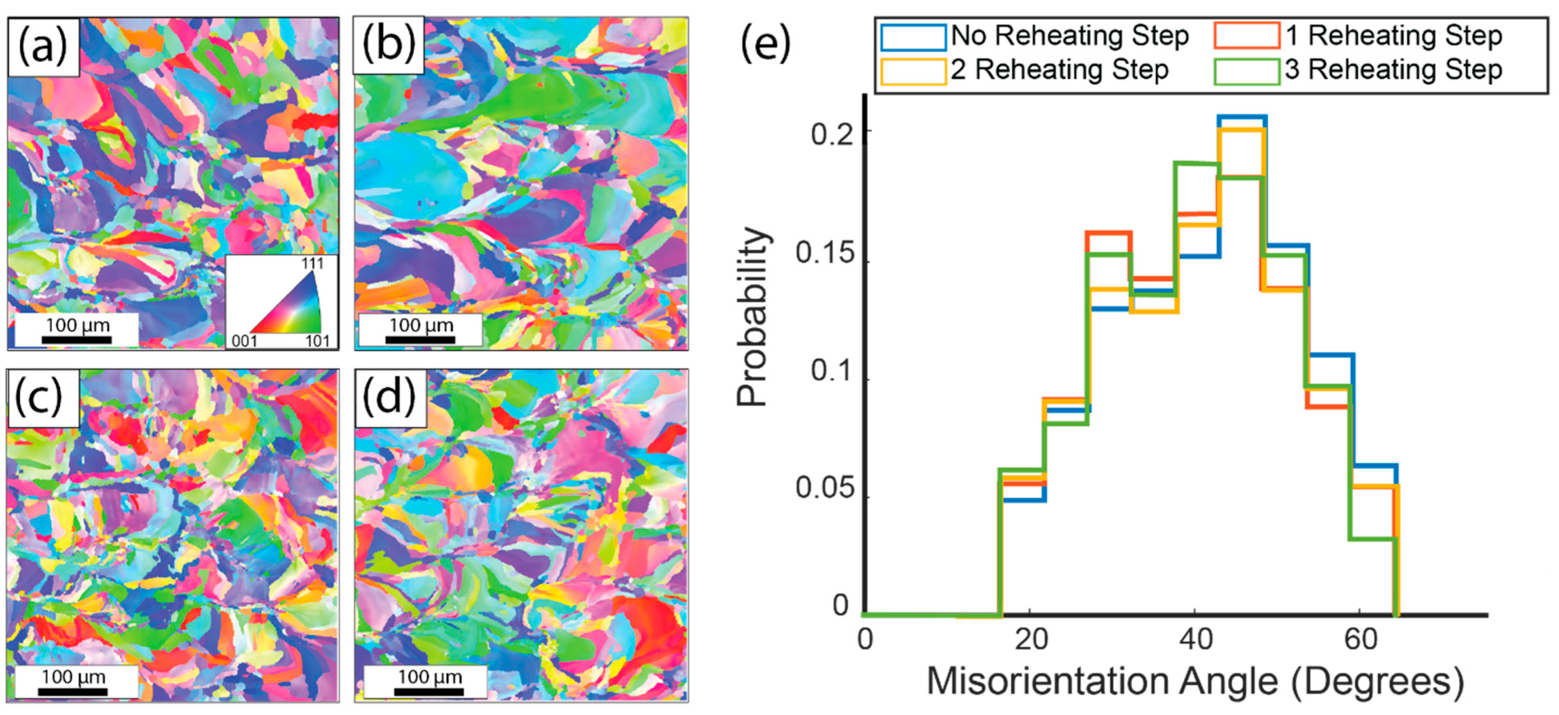
To examine the impact of the optimized process parameters (both melting and reheating scans, case (a)) on grain boundary angles, an experiment was carried out on 2507 super duplex stainless steel. Four samples were printed using the optimized parameters listed in Table 1 (#5): one sample without preheating and three samples with one, two, and three preheating steps, respectively. This approach aimed to create a diverse range of samples for comparison and analysis. Subsequently, Electron Backscatter Diffraction (EBSD) analysis was performed on each sample to visualize the misorientation angles of the grain boundaries. The resulting EBSD maps, shown in Figure 3a–d, provided valuable insights into the microstructural changes resulting from preheating.
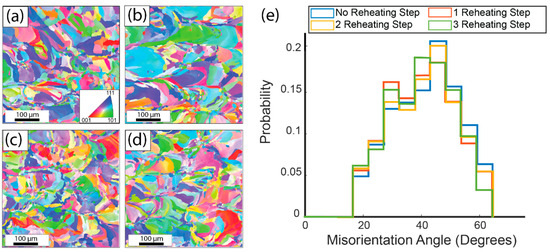
Figure 3.
EBSD maps of 2507 duplex stainless-steel samples with varying numbers of reheating scans. (a) Sample without preheating, (b) Sample with one preheating scan, (c) Sample with two preheating scans, (d) Sample with three preheating scans. (e) Plot of misorientation angles revealing the relationship between the number of reheating scans and the occurrence of high-angle grain boundaries.
Interestingly, the examination of the EBSD maps revealed that the grain size and texture of the samples remained relatively consistent regardless of the number of reheating scans. This observation suggests that the reheating process had minimal influence on the grain size and texture. However, a significant finding emerged concerning the number of very high-angle grain boundaries (>45°): an increase in the number of reheating scans corresponded to a decrease in the number of high-angle grain boundaries. This finding aligns with the initial hypothesis of the study, indicating that controlled increases in the number of reheating scans lead to higher levels of dynamic recovery, consequently impacting the angles of the grain boundaries.
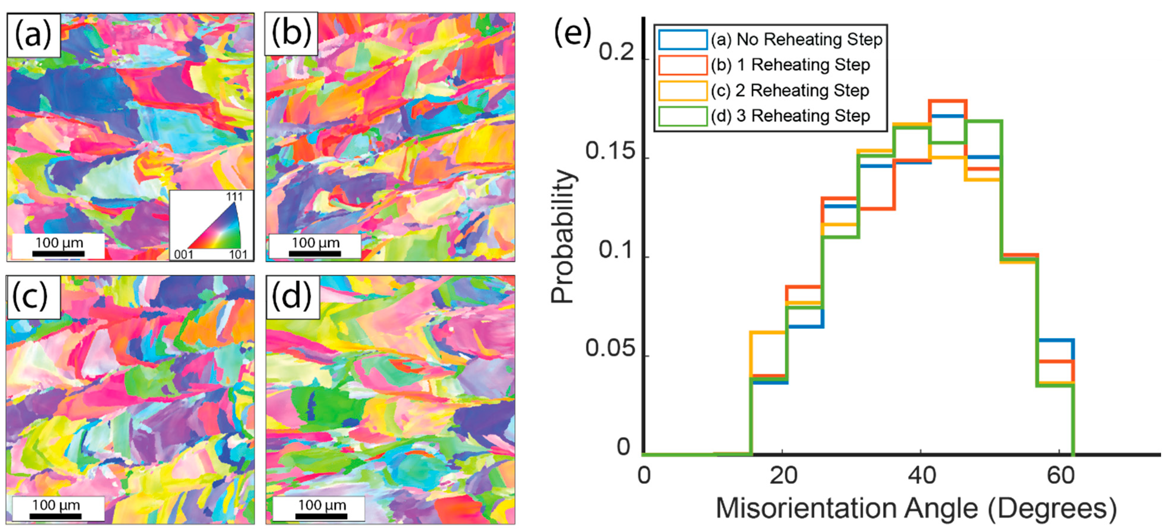
To confirm the validity of the optimized parameters in case (b), and evaluate the feasibility of the proposed method for other alloys, similar investigations were carried out on 316L austenitic steel. The first sample was fabricated without any preheating, utilizing the optimized parameters (Power = 310 W, Velocity = 1100 mm/s, hatch space = 90 μm, layer thickness = 40 μm). The subsequent three samples were produced using the optimized reheating scans (Reheating: Power = 26 W, Velocity = 11,000 mm/s, hatch space = 20 μm, layer thickness = 40 μm, Energy = 30), with one, two, and three reheating scans, respectively.
Figure 4 illustrates the resulting grain structures. Consistent with previous observations (as shown in Figure 3), no significant changes in the grain size and texture were observed among the samples. Moreover, Figure 4e highlights a decrease in the grain boundary angles with an increasing number of optimized preheating scans. This observation further supports the notion that the proposed optimization method can be applied regardless of the material composition.

Figure 4.
EBSD maps of 316L austenitic steel samples with varying numbers of reheating scans. (a) Sample without preheating, (b) Sample with one reheating scan, (c) Sample with two reheating scans, (d) Sample with three reheating scans. (e) Plot illustrating the relationship between the number of reheating scans and grain boundary angles.
The observed reduction in high-angle grain boundaries has significant implications for the mechanical properties of the material, particularly in terms of improved strength and ductility. High-angle grain boundaries can hinder the movement of dislocations within the material, leading to increased strength [8]. By reducing the number of high-angle grain boundaries through controlled reheating scans, we can enhance the overall mechanical performance of the printed components. Future research will aim to gain a deeper understanding of the relationship between reheating scans and the reduction in grain boundary angles, and how this relates to the material’s mechanical properties. Specifically, we will investigate the precise mechanisms through which reheating scans influence grain boundary angles and how these changes affect the material’s strength, ductility, and other mechanical characteristics. Moreover, the reproducibility of the proposed method will be a focal point, with explorations into various compositions and process parameters to ensure consistent and reliable outcomes. By uncovering these relationships, we will be able to optimize the parameters of the reheating scan process for additive manufacturing. This optimization will result in improved control over the grain boundary properties and the enhanced mechanical performance of the manufactured components.
3. Conclusions
This study investigated the effects of in situ heat treatment on the microstructure of L-PBF parts made from 316L austenitic steel and 2507 super-duplex stainless steel. A fundamental understanding of the grain boundaries in metallic materials reveals that these interfacial defects significantly influence mechanical and physical properties, acting as barriers to the dislocation motion and impacting aspects such as strength, ductility, and resistance to degradation forms like corrosion and creep. In the context of the rapidly evolving field of AM, especially the widely acclaimed L-PBF, achieving precise control over microstructural characteristics, particularly the properties and nature of grain boundaries, remains a pivotal challenge. GBE has emerged as a game-changing approach to enhancing these properties in L-PBF components, with the ability to modify grain boundary properties layer-by-layer. In this study, our core endeavor was to utilize the promise of GBE through an innovative in situ heat treatment for L-PBF components. We developed a thermal model, simulating the thermal cycling experienced by each point during the L-PBF process. The objective, rooted in the principles of grain boundary engineering, was to maximize dynamic recovery and control grain boundary angles. The validation of this model on the duplex stainless steel showcased a heightened dynamic recovery and a reduction in high-angle grain boundaries (>45°). This not only improved the strength and flexibility of the components, but also signified the potential of in situ heat treatment in the broader landscape of additive manufacturing. To further cement the reliability and adaptability of this method, experiments conducted on 316L austenitic steel echoed similar positive outcomes in grain boundary angles and grain size consistency. The findings of this research pave the way for an advanced grain boundary engineering approach in L-PBF. They underscore the need for in-process microstructure control, which could trump traditional post-processing techniques when dealing with complex geometries. The results also shed light on the broader potential of in situ heat treatment in additive manufacturing, fortifying the belief that grain boundary engineering is instrumental in optimizing the manufacturing process of high-performance components.
Author Contributions
Conceptualization, M.T.A., V.S. and A.M.; data curation, M.T.A.; writing—original draft preparation, M.T.A.; writing—review and editing, V.S. and A.M.; supervision, V.S. and A.M. All authors have read and agreed to the published version of the manuscript.
Funding
The authors of this paper declare that no funding or financial support was received for the research, creation, or publication of this work.
Conflicts of Interest
The authors declare no conflict of interest.
References
- Gao, W.; Zhang, Y.; Ramanujan, D.; Ramani, K.; Chen, Y.; Williams, C.B.; Wang, C.C.; Shin, Y.C.; Zhang, S.; Zavattieri, P.D. The status, challenges, and future of additive manufacturing in engineering. Comput.-Aided Des. 2015, 69, 65–89. [Google Scholar] [CrossRef]
- Huang, Y.; Leu, M.C.; Mazumder, J.; Donmez, A. Additive manufacturing: Current state, future potential, gaps and needs, and recommendations. J. Manuf. Sci. Eng. 2015, 137, 014001. [Google Scholar] [CrossRef]
- Frazier, W.E. Metal additive manufacturing: A review. J. Mater. Eng. Perform. 2014, 23, 1917–1928. [Google Scholar] [CrossRef]
- Kotadia, H.; Gibbons, G.; Das, A.; Howes, P. A review of Laser Powder Bed Fusion Additive Manufacturing of aluminium alloys: Microstructure and properties. Addit. Manuf. 2021, 46, 102155. [Google Scholar] [CrossRef]
- Kusoglu, I.M.; Gökce, B.; Barcikowski, S. Research trends in laser powder bed fusion of Al alloys within the last decade. Addit. Manuf. 2020, 36, 101489. [Google Scholar] [CrossRef]
- Sing, S.L.; Yeong, W.Y. Laser powder bed fusion for metal additive manufacturing: Perspectives on recent developments. Virtual Phys. Prototyp. 2020, 15, 359–370. [Google Scholar] [CrossRef]
- Hirth, J.P. The Influence of Grain Boundaries on Mechanical Properties; Springer: Berlin/Heidelberg, Germany, 1972. [Google Scholar]
- Kacher, J.; Eftink, B.; Cui, B.; Robertson, I. Dislocation interactions with grain boundaries. Curr. Opin. Solid State Mater. Sci. 2014, 18, 227–243. [Google Scholar] [CrossRef]
- Thapliyal, S.; Agrawal, P.; Agrawal, P.; Nene, S.S.; Mishra, R.S.; McWilliams, B.A.; Cho, K.C. Segregation engineering of grain boundaries of a metastable Fe-Mn-Co-Cr-Si high entropy alloy with laser-powder bed fusion additive manufacturing. Acta Mater. 2021, 219, 117271. [Google Scholar] [CrossRef]
- Sabzi, H.E.; Hernandez-Nava, E.; Li, X.-H.; Fu, H.; San-Martín, D.; Rivera-Díaz-del-Castillo, P.E. Strengthening control in laser powder bed fusion of austenitic stainless steels via grain boundary engineering. Mater. Des. 2021, 212, 110246. [Google Scholar] [CrossRef]
- Li, J.; Qu, H.; Bai, J. Grain boundary engineering during the laser powder bed fusion of TiC/316L stainless steel composites: New mechanism for forming TiC-induced special grain boundaries. Acta Mater. 2022, 226, 117605. [Google Scholar] [CrossRef]
- Abdi, F.; Eftekharian, A.; Huang, D.; Rebak, R.B.; Rahmane, M.; Sundararaghavan, V.; Kanyuck, A.; Gupta, S.K.; Arul, S.; Jain, V. Grain boundary engineering of new additive manufactured polycrystalline alloys. Forces Mech. 2021, 4, 100033. [Google Scholar] [CrossRef]
- Rezayat, M.; Karamimoghadam, M.; Moradi, M.; Casalino, G.; Roa Rovira, J.J.; Mateo, A. Overview of Surface Modification Strategies for Improving the Properties of Metastable Austenitic Stainless Steels. Metals 2023, 13, 1268. [Google Scholar] [CrossRef]
- Fayazfar, H.; Salarian, M.; Rogalsky, A.; Sarker, D.; Russo, P.; Paserin, V.; Toyserkani, E. A critical review of powder-based additive manufacturing of ferrous alloys: Process parameters, microstructure and mechanical properties. Mater. Des. 2018, 144, 98–128. [Google Scholar] [CrossRef]
- Gatsos, T.; Elsayed, K.A.; Zhai, Y.; Lados, D.A. Review on computational modeling of process–microstructure–property relationships in metal additive manufacturing. Jom 2020, 72, 403–419. [Google Scholar] [CrossRef]
- Lesyk, D.; Martinez, S.; Mordyuk, B.; Pedash, O.; Dzhemelinskyi, V.; Lamikiz, A. Ultrasonic surface post-processing of hot isostatic pressed and heat treated superalloy parts manufactured by laser powder bed fusion. Addit. Manuf. Lett. 2022, 3, 100063. [Google Scholar] [CrossRef]
- Ardi, D.T.; Guowei, L.; Maharjan, N.; Mutiargo, B.; Leng, S.H.; Srinivasan, R. Effects of post-processing route on fatigue performance of laser powder bed fusion Inconel 718. Addit. Manuf. 2020, 36, 101442. [Google Scholar] [CrossRef]
- Sripada, J.; Tian, Y.; Chadha, K.; Saha, G.; Jahazi, M.; Spray, J.; Aranas Jr, C. Effect of hot isostatic pressing on microstructural and micromechanical properties of additively manufactured 17–4PH steel. Mater. Charact. 2022, 192, 112174. [Google Scholar] [CrossRef]
- Peng, X.; Kong, L.; Fuh, J.Y.H.; Wang, H. A review of post-processing technologies in additive manufacturing. J. Manuf. Mater. Process. 2021, 5, 38. [Google Scholar] [CrossRef]
- Kumbhar, N.N.; Mulay, A. Post processing methods used to improve surface finish of products which are manufactured by additive manufacturing technologies: A review. J. Inst. Eng. Ser. C 2018, 99, 481–487. [Google Scholar] [CrossRef]
- Bertoli, U.S.; MacDonald, B.E.; Schoenung, J.M. Stability of cellular microstructure in laser powder bed fusion of 316L stainless steel. Mater. Sci. Eng. A 2019, 739, 109–117. [Google Scholar] [CrossRef]

Disclaimer/Publisher’s Note: The statements, opinions and data contained in all publications are solely those of the individual author(s) and contributor(s) and not of MDPI and/or the editor(s). MDPI and/or the editor(s) disclaim responsibility for any injury to people or property resulting from any ideas, methods, instructions or products referred to in the content. |
© 2023 by the authors. Licensee MDPI, Basel, Switzerland. This article is an open access article distributed under the terms and conditions of the Creative Commons Attribution (CC BY) license (https://creativecommons.org/licenses/by/4.0/).