Review

Progress on the Effect and Mechanism of Ultrasonic Impact Treatment on Additive Manufactured Metal Fabrications

1
Harbin Welding Institute Limited Company, Harbin 150028, China
2
School of Materials Science and Engineering, Harbin Institute of Technology, Harbin 150001, China
*
Authors to whom correspondence should be addressed.
Crystals 2023, 13(7), 995; https://doi.org/10.3390/cryst13070995
Submission received: 13 June 2023 / Revised: 16 June 2023 / Accepted: 16 June 2023 / Published: 22 June 2023
(This article belongs to the Special Issue Additive Manufacturing of Metallic Alloys)

Abstract

:
Metal fabrications experience complex physical metallurgical processes during additive manufacturing, leading to residual stress and coarse microstructure with directional growth. It significantly affects the comprehensive performance of the fabrications, which limits the application of additive manufacturing. Ultrasonic impact treatment (UIT), as a strengthening means to assist additive manufacturing, can effectively improve the stress state and refine the microstructure and the comprehensive performance. This paper introduces the effect of UIT on AM metal fabrications on microstructure morphology, stress distribution, surface roughness, internal defects, and comprehensive performance to gain a deeper understanding of the role of UIT on additively manufactured metal fabrications, which is based on the working principle and effect of process parameters. In addition, the strengthening mechanism of UIT in additive manufacturing is described from the perspective of surface plastic deformation and substructure formation, providing support for the shape and property control of metal fabrications in the process of additive manufacturing assisted by UIT. Finally, the issues that need to be studied in depth on UIT in additive manufacturing are summarized, and an outlook on future research directions is taken.

1. Introduction

Additive manufacturing (AM) has been rapidly developed in the past three decades thanks to the remarkable progress in computer technology and heat source development, which has gained widespread attention due to its high flexibility, high deposition efficiency, and high material utilization [1,2,3,4]. However, limited by the heat source and deposition characteristics, the solidification microstructure of the additive manufactured metal deposition is dominated by coarse columnar dendrite with significant directional growth due to the temperature gradient [5], leading to many critical problems [6], such as significant anisotropy, residual stress, and even deformation or crack. For this reason, researchers have proposed to improve the problem by various strengthening means, mainly including laser shock peening (LSP) [7], rolling [8], machine hammer peening (MHP) [9], ultrasonic vibration (UV) [10], and ultrasonic impact treatment (UIT) [11]. Compared with other means of interlayer strengthening, ultrasonic impact treatment shows some unique advantages: low cost, satisfying quality guarantee, flexible operation, and environmentally friendly process. Especially it can be integrated with other equipment to achieve efficient automated processing [12].
Ultrasonic impact treatment was first proposed and designed by the famous Soviet scientist Statnikov in the 1960s. This technology was used to improve the strength and prolong the service life of the treated parts. In the 1970s, Soviet scientists applied ultrasonic impact treatment to the aerospace field, and the treated material performance was greatly improved [13]. By the mid-1990s, the Paton Institute of Welding of the National Academy of Sciences of Ukraine, in conjunction with Canadian research institutions, made a detailed report on the superiority of ultrasonic impact treatment in the welding field systematically, which provides a theoretical basis for the subsequent large-scale application of this technique and has been highly valued by the International Welding Institute [14]. With continuous and deep research on ultrasonic impact treatment, the equipment process control has been greatly improved and perfected. With rapid development, ultrasonic impact treatment has been widely used in refining the microstructure, residual stress control, surface roughness, and mechanical property improvement of metal parts in some manufacturing areas, achieving impressive effects [15,16,17,18].
In additive manufacturing, ultrasonic impact treatment, as an auxiliary reinforcement measure, has also been widely recognized by researchers. It has been studied deeply in additive manufacturing fields such as laser metal deposition and wire and arc additive manufacturing [19,20,21,22,23,24]. Based on the strengthening mechanism and process parameter effect, this paper summarizes the microstructure variation, stress state, surface roughness, defects, and comprehensive performance of metal parts when introducing ultrasonic impact treatment in the deposition process. It aims to apply the technique in the field of additive manufacturing more effectively. Finally, the problems to be solved in the current stage and future research to be worked on are discussed.

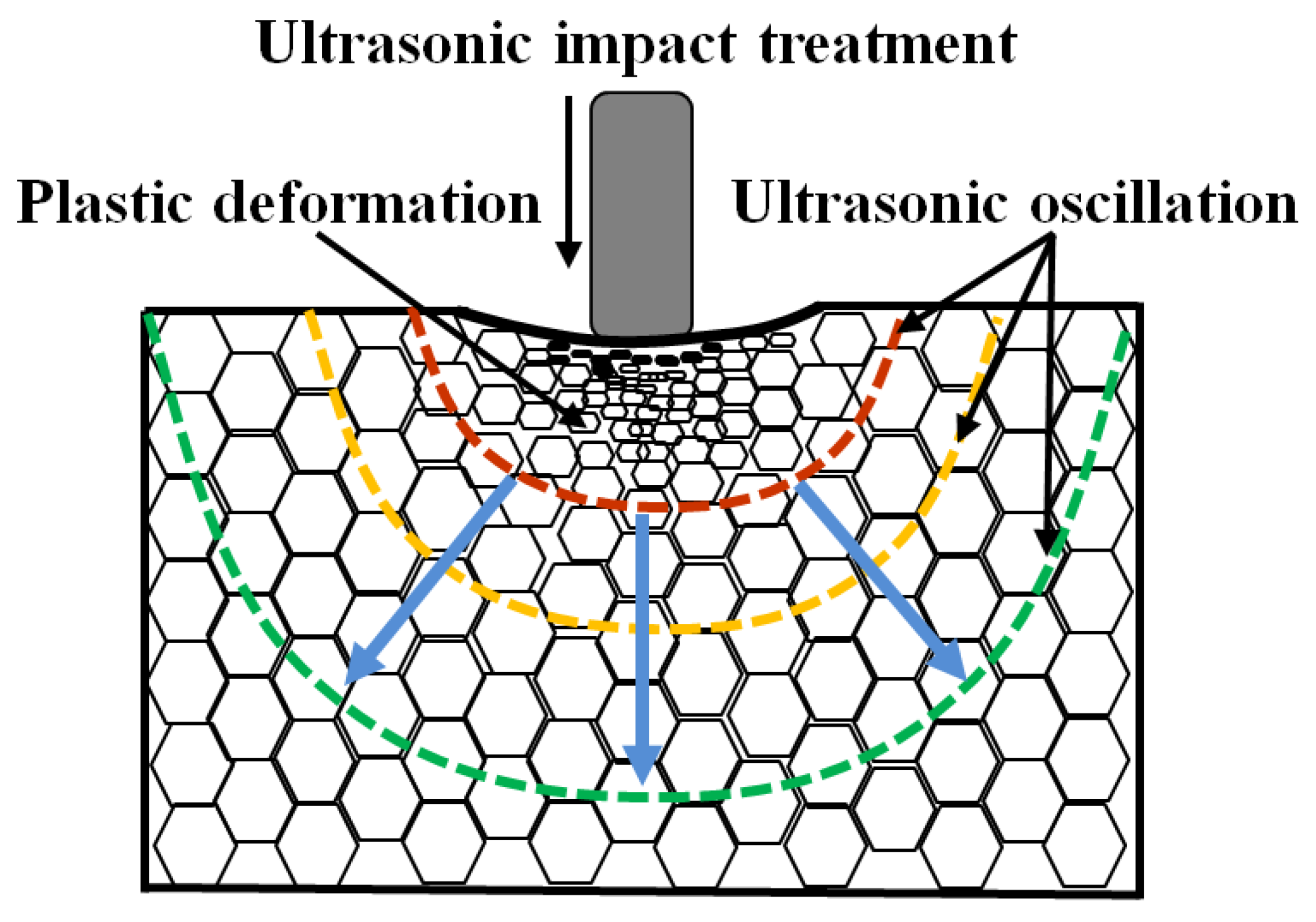
2. Working Principle and Role of Various Process Parameters

Ultrasonic impact treatment is a method to achieve strengthening by the high-frequency impact on the surface of the workpiece, which is driven by high-power ultrasound through a transducer that converts electrical energy into high-frequency (20–55 kHz) amplitude (20–50 μm). The transducer can drive the needle to impact the metal material’s surface by amplifying/concentrating energy, thus achieving the strengthening effect [25]. A UIT process consists of five steps: (1) the ultrasonic generator I induces the vibrations; (2) the vibration transmission controls the vibration speed; (3) the transducer II transmits the energy in the form of pulses to the impact needle III; (4) the impact needle acts on the surface of the workpiece IV in the form of pulses; (5) the ultrasonic vibrations (part 1) will be converted into mechanical pulses (part 2), acting on the surface of the workpiece IV. The specific equipment structure and working principle schematic diagram are shown in Figure 1 [26].
Ultrasonic impact treatment is a complex and non-stationary process with high instantaneous strain. The process parameters (impact frequency, number of impacts, impact velocity, impact angle, impact coverage, number of impact pins, adjacent distance of impact pins, impact pin shape, impact pin length, etc.) show different effects on the fabrications. The effects of these process parameters on stress distribution, resistance to crack propagation, effective impact depth, and degree of surface plastic deformation are shown in Table 1.
The number of impacts is directly affected by the impact frequency, number of impact pins, and impact duration, which in turn reflects in the impact coverage. It ultimately can be attributed to the number of impacts per unit area. The influence of the number of impacts on the material’s surface can be divided into two stages. In the first stage, the pin impacts the material surface, producing severe plastic deformation in the area of action. With increasing the number of impacts, work hardening induced by plastic deformation becomes more pronounced. The surface hardness of the material and the effective depth influenced by UIT also increase. In addition, the residual tensile stress generated during the additive manufacturing deposition is continuously released. It gradually introduces residual compressive stress on the material surface, as shown in Figure 2 [37]. For a specific material, the surface hardness and residual compressive stress reach the maximum when performing a certain number of impacts. In the second stage, due to the effect of work hardening, with increasing the number of impacts, significant plastic deformation can not be observed in the treated region, and the surface hardness tends to stabilize. However, under the effect of the high-frequency dynamic cyclic loading of UIT, the treated area is influenced by ultrasonic oscillations. The atoms exhibit an excited state by stress waves, and resonance happens, reducing the lattice distortion energy. As the number of impacts continues to increase, the residual compressive stress that has been introduced on the material surface will be released under the fatigue load, making the residual compressive stresses smaller. When the number of impacts is too many because of the improper impact parameter setting, defects such as folding or fatigue cracks are apt to form on the material surface.
Impact velocity also plays a significant role in affecting the impact effect. It determines the kinetic energy of the impact pin when it interacts with the material, significantly affecting the strain distribution in the treated region. Zhang developed a model of single needle impact to further visualize the needle impact, which is based on the platform of ABAQUS. He proposed a positive correlation between the impact velocity and the strain [35]. As the impact velocity increases, the equivalent plastic strain (PEEQ) distribution becomes progressively larger and wider, as shown in Figure 3. It indicates that the plastic deformation caused by the impact pin becomes more significant, and the size of the indentation produced by the impact increases. The differences in impact velocity lead to the above changes. It is mainly because as the impact velocity increases, each impact has greater kinetic energy interacting with the material surface. It will cause greater impact plastic deformation and introduce more significant residual compressive stress and effective depth of UIT, further affecting the ability of the metal material to resist crack propagation.
In the actual UIT process, the impact needle collides with the material in a high-speed non-stationary way, which means that it is challenging to achieve frontal collision in an ideal model of the impact needle and the material surface. The different impact mode (impact angle and impact needle shape) determines the contact way and friction state between the impact needle and the material surface. It will eventually reflect the differences in the indentation shape, size, and residual stress distribution. When the impact needle interacts with the surface in an ideal (vertical) manner, the indentation profile and stress distribution remain symmetrical. When the impact angle is offset, the indentation shows a non-symmetrical state. Energy will generate components at a certain angle toward action depth. The indentation depth, residual stress improvement, and equivalent plastic strain are reduced, meaning the effect of UIT is weakened. In addition, the impact needle shape also significantly affects the impact effect. With increasing the impact needle diameter and length, the UIT effective depth and the maximum residual compressive stress increase, as shown in Figure 4a,b [37]. Since the UIT system gives the impact needle the same initial velocity during the UIT process, the impact needle’s mass determines kinetic energy. As the diameter and length of the impact needle increase, its mass also increases, meaning more energy will be transferred into the target material when it acts on the material surface. It eventually leads to the above changes in residual stresses. When the semi-axis of the impact needle becomes larger (the impact needle head is sharper), the impact needle’s ability to act on the material surface is more concentrated, causing more obvious elastic and plastic deformation. A narrower and deeper indentation can be obtained. When the semi-axis is smaller, the indentation shape is wider and shallower. The changes will directly reflect in the residual stress distribution of the material surface. The maximum residual stress gradually increases with increasing the semi-axis of the impact needle. The effective impact depth and the maximum residual stress depth will decrease, which is mainly related to the concentration of energy transfer after varying the shape of the impact needle, as shown in Figure 4c,d [37].
Impact amplitude and load are closely related to the energy of the impact needle in the UIT process. As these two parameters increase, the impact needle will transfer more kinetic energy to the material, improving the effect of UIT so as to the effective impact depth and residual stress. In addition, with the increase in impact load, various types of defects in the rapid melting and solidification of metal deposition can also be eliminated to improve the fabrication quality to a certain extent.
In addition, when multiple impact pins are applied, the distance between adjacent impact pins determines the degree of their mutual influence. Guo developed two 3D models, a single-impact model and a two-impact model, using ABAQUS/Explicit finite element code to simulate the residual stress distributions of UIT within the target plate. The result indicates that when the interval distance is small, the effect of UIT tends to cause changes in the direction of the impact depth. The effective impact depth influenced by interference is greater than that of the single impact pin. As the interval distance increases, the impact effect changes from the depth to the width. The effective impact depth decreases, and the width increases after the multiple impact pin interference influences the fabrication. As the interval distance increases, the interference effect between the adjacent needles gradually decreases until there is no influence on each other. In this case, the impact effect of multiple impact pins is the same as that of single-needle impact, as shown in Figure 5 [34].
From the above elaboration, it is clear that the differences in process parameters can significantly affect the impact effect in terms of impact indentation shape, surface hardness, equivalent plastic strain, residual stress, and resistance to crack propagation [39]. The influence mainly comes from the fact that different UIT process parameters can cause changes in impact energy, impact mode of action, and impact interference. What’s more, UIT can also lead to other transformations, such as homogenizing the melt pool temperature by increasing the heat transfer to the core of the melt pool [40]. While, this paper only describes the fields that attracted more attention from researchers. UIT generally shows satisfactory applicability and operability in additive manufacturing parts with different sizes, shapes, and complexity [41].

3. Effect of UIT on AM Fabrications

As is known to all, UIT can cause significant changes in AM fabrication mainly through the combined effect of surface plastic deformation and ultrasonic oscillation stress waves. Its most intuitive characteristic is to form a severe plastic deformation layer on the material’s surface, obtaining a surface rheological microstructure by breaking the grains [42,43,44,45]. This effect can markedly improve the coarse microstructure with directional growth and promote the columnar to equiaxed transition (CET), leading to grain refinement [46]. Another vital effect caused by UIT is restructuring the stress state and introducing residual compressive stresses that benefit the fabrication’s overall properties. It effectively improves fabrication bending and deformation caused by unbalanced stress distribution and stress concentration during metal deposition. On this condition, the solidification crack can be significantly suppressed by introducing UIT in the additive manufacturing process of metals with high crack sensitivity, improving the fabrication quality. In addition, the multiple high-frequency transient impacts generated by UIT on the fabrication surface will smooth the micro-bumps, which is positive for improving the surface roughness. UIT can induce a series of changes in metal fabrications during the additive manufacturing process that leads to a significant improvement in the overall performance (including mechanical properties, fatigue strength [47], wear resistance [48], corrosion resistance, etc.). To illustrate the effects of UIT on AM fabrications, the description of microstructure evolution, stress state, surface state, defects, and comprehensive performance are made below.

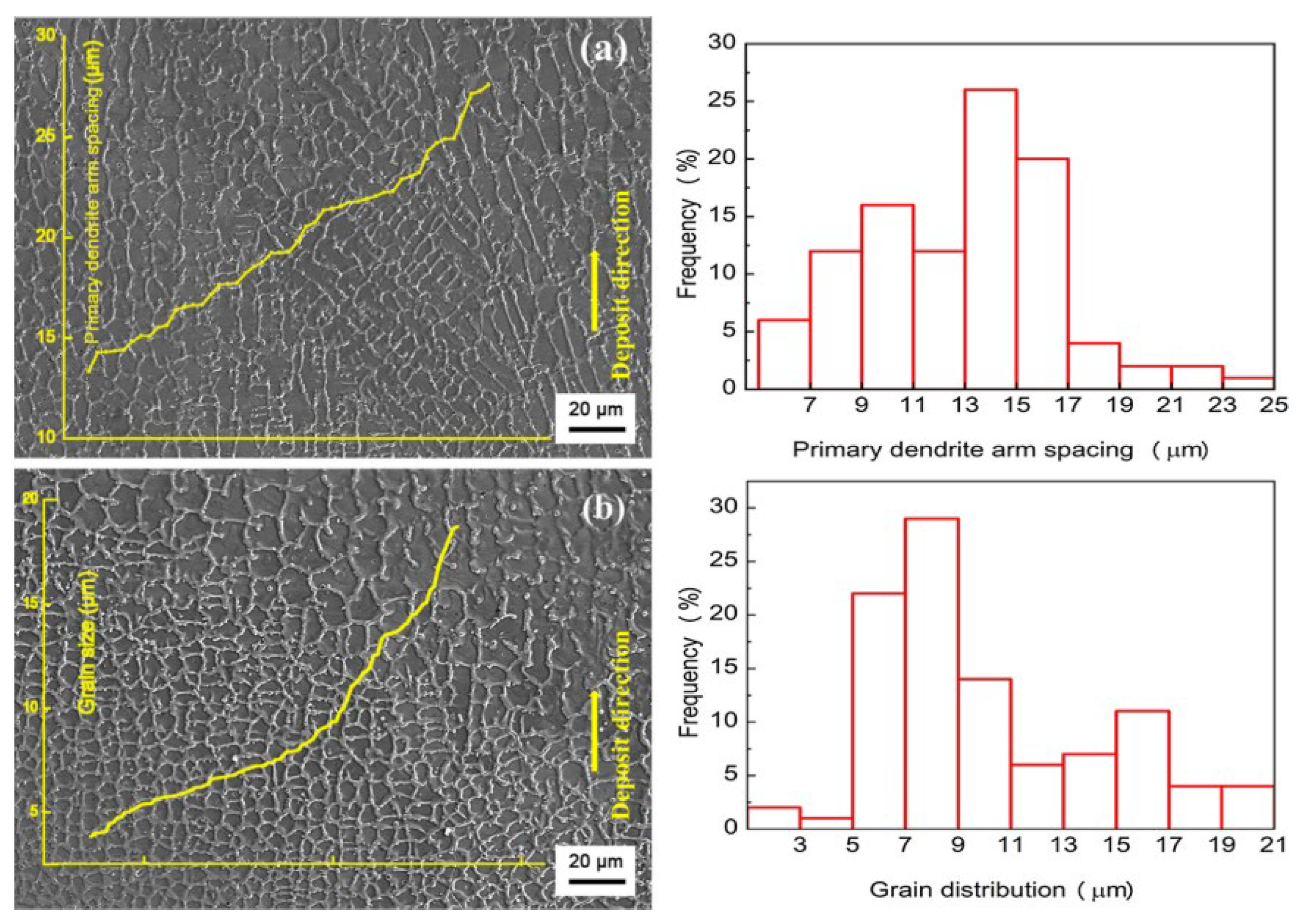
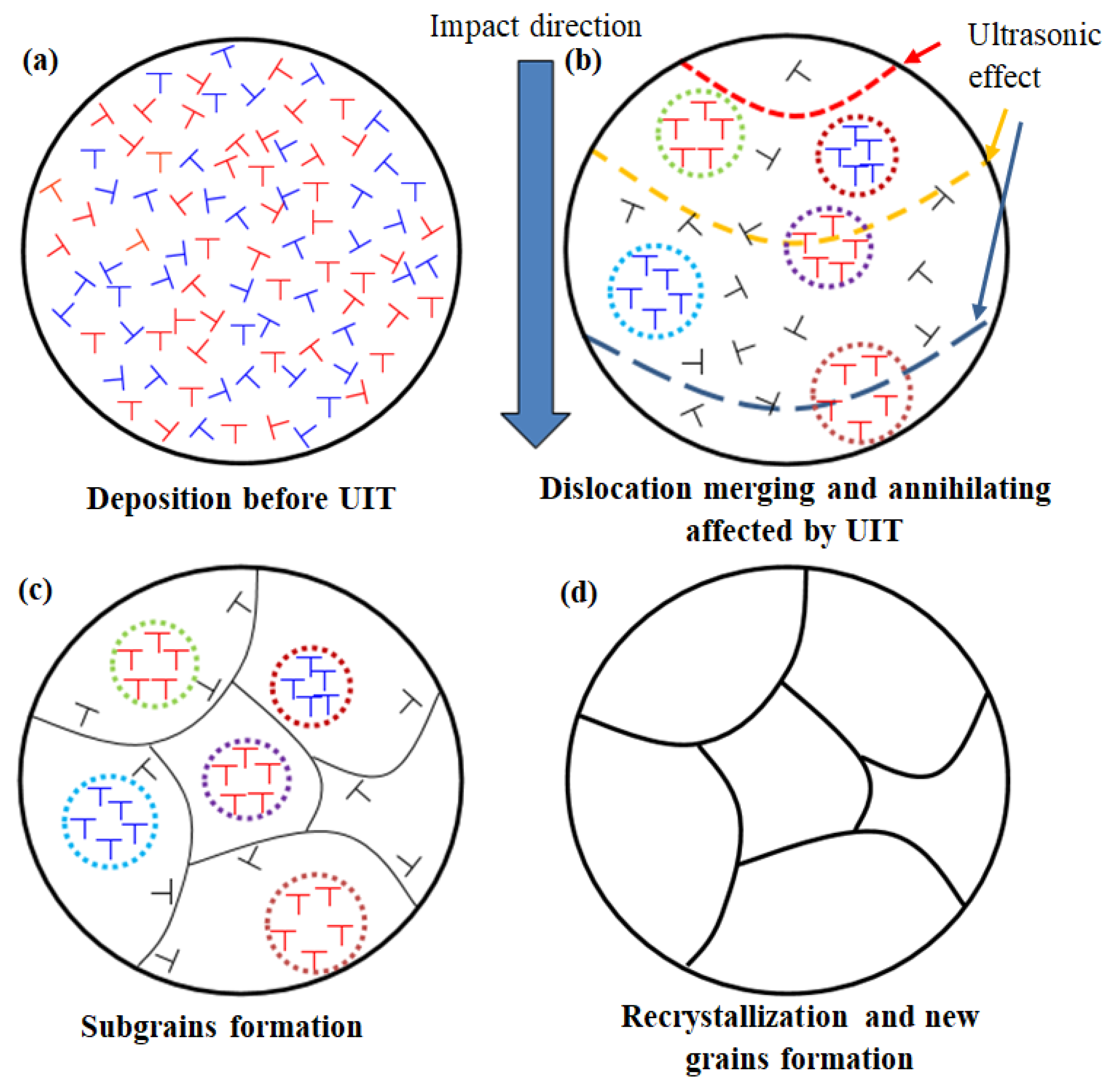
3.1. Microstructure Improvement and Grain Refinement

One of the most critical advantages of UIT in strengthening AM fabrication is to improve the microstructure and refine the grains. Xu [49] found that introducing UIT can improve the microstructure state when fabricating high-strength Hastelloy X superalloy in laser directed energy deposition process. The microstructure comparison between fabrications with and without UIT is shown in Figure 6. After applying UIT, a decrease in the proportion of columnar grains and an increase in the proportion of equiaxed grains are observed in the deposition. The average grain size decreases from 19.81 μm to 8.78 μm, and the primary dendrite spacing from the bottom to the top of the deposition varies from 13.35–27.62 μm (Figure 6a) to 3.78–18.33 μm (Figure 6b). It indicates that UIT can effectively break the original columnar grains to form more uniform and refined grains. The broken and refined grains can also provide more nucleation sites in the subsequent deposition process, thus inducing grain refinement.
Sun [50] obtained a similar result using UIT-assisted wire and arc wire additive manufacturing (WAAM) of low-carbon high-strength steel. Figure 7 shows the macrostructure comparison of the deposited layers with and without UIT. It can be seen that the macrostructure without UIT consists of a large number of coarse columnar grains and a small number of equiaxed grains, which are common in the WAAM process, showing noticeable directional growth. However, after applying UIT, the macrostructure is mainly composed of equiaxed grains, and the grains are significantly refined, as shown in Figure 7b. It means that UIT contributes to microstructure improvement and grain refinement in the additive manufacturing process and can effectively promote the transformation of columnar grains to equiaxed grains.
The reason for the microstructure improvement and grain refinement after UIT mainly comes from the severe plastic deformation of the material surface, which leads to dislocation multiplication within the grain and an increase in dislocation density [51]. With the further accumulation of energy, several dislocation walls or dislocation cells are formed within the grain, which will increase in rotation angle. Then, the texture orientation increases between the adjacent substructures, which will transform into subgrains, leading to a complete large-angle grain boundary. Finally, many small grains are formed within the original single grain, achieving grain refinement [52].

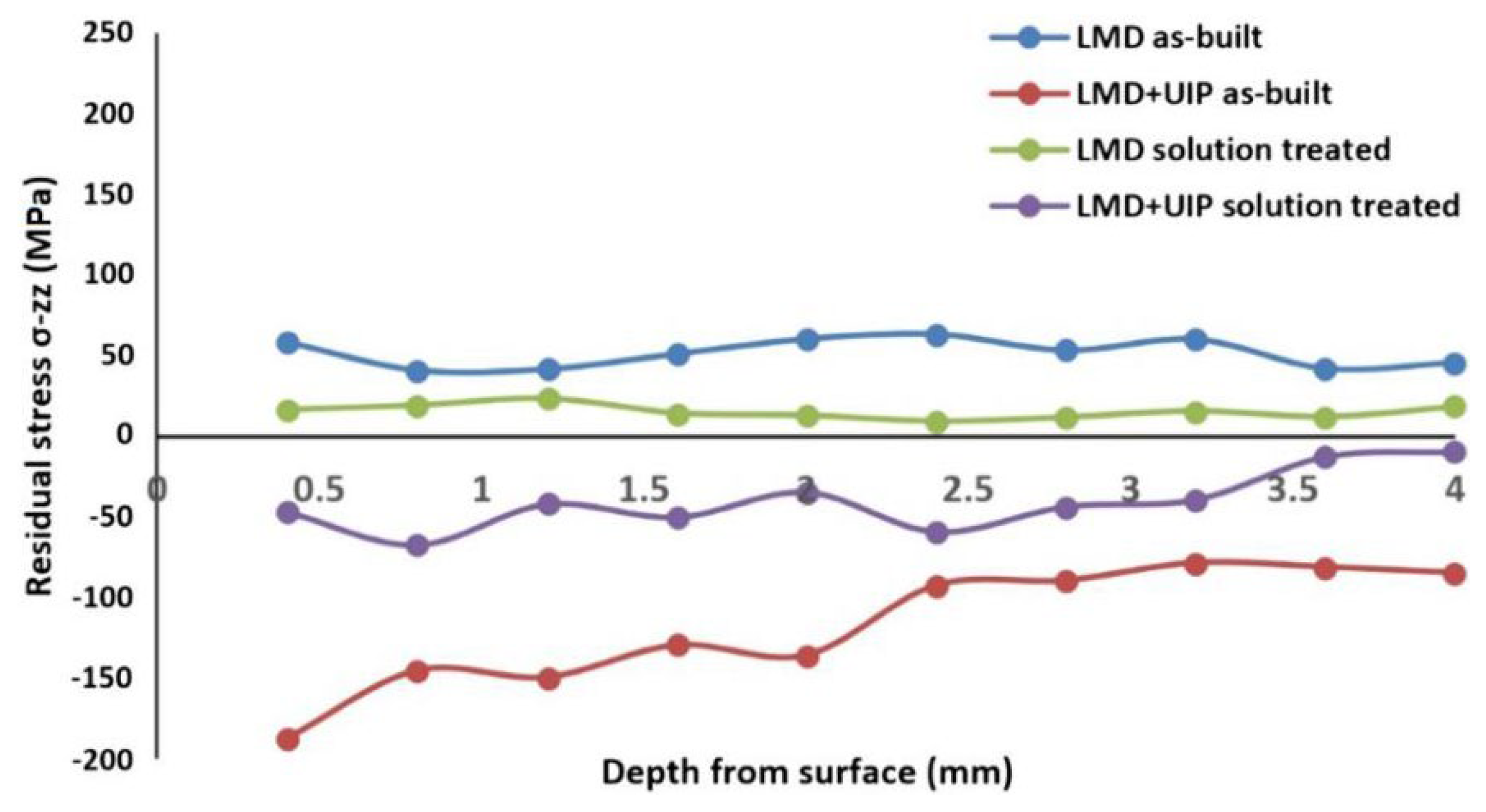
3.2. Stress Reconstruction

In addition to the microstructure improvement and grain refinement, UIT also shows unique advantages in reconstructing the stress distribution state. Wang [53] found that the fabrications under different states showed various residual stress distributions when depositing Inconel 718 with laser metal deposition (LMD) assisted by UIT, as shown in Figure 8. As seen in the figure, the residual tensile stress of the untreated fabrication is 53 MPa (on average), which was completely transformed into a residual compressive stress with a maximum value of 190 MPa after applying UIT. With increasing the depth to 2.5 mm from the treated surface, the residual compressive stress gradually decreases and finally stabilizes around 110 MPa. When treated by UIT and solution treatment, a large amount of deformation energy storage is caused by plastic deformation within UIT’s influence, which drives recrystallization and grain refinement in the subsequent laser reheating process. In this case, the stress will be released but still presents a significant residual compressive stress.
Zhang [54] also proposed a similar viewpoint that the material experienced rapid melting, solidification, and cooling during the additive manufacturing process, resulting in considerable residual tensile stress. This stress state can exist in an unstable high-energy form, which increases the slip resistance and tends to cause stress concentration in this region. After introducing UIT, under the recombination action of ultrasonic oscillation, high-frequency vibration, and impact stress, the stress is partially released in areas with a higher stress field, eliminating residual tensile stress. In addition, affected by UIT, a large number of dislocation in the deposition gets enough energy to slip or climb free from the surrounding bindings and obstacles, which results in the energy decrease in the original stress concentration area. Finally, the overall stress state is redistributed and stabilized.

3.3. Surface Roughness Improvement

UIT can cause severe plastic deformation (SPD) when it makes an intense collision with the material. The surface bumps and depressions can be flattened under severe plastic deformation, improving the surface roughness significantly. Lv [55] used UIT to strengthen Ti-6Al-4V titanium alloy during cold metal transfer additive manufacturing (CMTAM). The 2D and 3D surface profile of depositions before and after UIT were scanned by KEYENCE confocal laser scanning microscope. The results showed that UIT could transform the regular scratches on the rough surface into a relatively smooth surface with uniform plastic deformation, reshaping the surface morphology of the deposition. It reduced the average and maximum surface height by about 41.1% and 36.3%, respectively, improving the surface roughness effectively, as shown in Figure 9. Malz [56] also obtained the same conclusion when using UIT to treat the surface of the deposition fabricated by direct metal laser sintering (DMLS). He found that severe plastic deformation happened on the original surface with incomplete melted powder and uneven deposited layers after being treated by UIT, which helped improve the rough surface condition in the process of additive manufacturing.
Improving surface roughness strengthens the corrosion resistance of additively manufactured fabrications. Wang [57] found a fact during the depositing of 316 L stainless steel with selective laser melting (SLM) that the raised and depressed areas on the surface after additive manufacturing were potential initiation points for pitting. These points are highly susceptible to the formation of stable pitting influenced by a corrosive condition, which in turn significantly affects the corrosion resistance of the fabrication. In addition, the improvement of surface roughness caused by UIT can also provide more stable forming conditions for the subsequent deposition, which helps to improve the melt pool stability and avoid the deterioration accumulation induced by dimensional fluctuations during the additive manufacturing process.

3.4. Defect Healing

In additive manufacturing, the metal experiences a rapid melting, cooling, and complex gas environment, which is prone to form many internal defects, such as cracks and porosity. It will seriously affect the fabrication quality and cause stress concentrations, leading to failure. Researchers proposed that UIT is beneficial for improving the defects in the additive manufacturing process. Wang [36] made an intelligent combination of direct energy deposition (DED) to moderate the crack susceptibility of Inconel 100 superalloys with high crack sensitivity. Figure 10 shows the crack distribution of Inconel 100 superalloy fabrications in different treated conditions. It can be seen that before introducing interlayer UIT, a large number of cracks existed in the deposition and propagated along the deposition direction, which was considered a common problem during the rapid melting and solidification of nickel-based high-temperature alloys [58,59]. In this condition, the crack density of the deposition is about 8.9 mm/mm2, as shown in Figure 10a. After being treated by interlayer UIT, the solidification cracking was significantly suppressed. The crack density was decreased to 4.2 mm/mm2 and 2.5 mm/mm2 when the impact load was 25 N and 50 N, respectively. It indicated that with the increase of impact load, although the solidification cracking still existed, the crack propagation was moderated, as shown in Figure 10b,c. The cracks almost completely disappeared when the impact load was increased to 75 N, as shown in Figure 10d.
On this basis, Wang [60] also found that UIT could solve the problem of pores generated in the 2219 aluminum alloy WAAM process. Figure 11 shows the distribution of pores in the deposition before and after UIT. It can be seen that a large number of micron-sized pores distribute inside the deposition under the influence of hydrogen ions generated by the arc. In this condition, the pore rate is about 19 pores/mm2, and the maximum pore diameter is about 120 mm. After being treated by UIT with 1 A current, the pores are extruded from round to oval. The pore rate is reduced to 9 pores/mm2 (57.9% reduction), and the maximum pore size is reduced to 36 mm (70% reduction). When the current is increased to 2.5 A, the number and size of pores are further reduced. The pore rate is decreased to 3 pores/mm2 (84.2% reduction), and the maximum pore diameter is 28 mm (76.7% reduction).

3.5. Comprehensive Performance Strengthening

The above changes caused by UIT will eventually be reflected in the comprehensive performance of the material, such as mechanical properties, wear resistance, fatigue and corrosion resistance, etc. Diao [61] used UIT to improve the mechanical properties of the ER321 stainless steel fabrications in the WAAM process, as shown in Figure 12. After applying UIT, yield strength (YS) increases from 380 MPa to 425 MPa (10.5% increase), ultimate tensile strength (UTS) increases from 667 MPa to 694 MPa (3.7% increase), total elongation (TE) increases from 48% to 50%, uniform elongations (UE) increases from 36% to 37%. The average microhardness increases from 195.27 HV0.3 to 223.42 HV0.3 (12.5% increase). The improvement in tensile properties is mainly attributed to grain refinement, as described by the Hall-Patch equation:
σ y = σ 0 + K y d ( 1 / 2 )
where σy is the strength of the material, σ0 is the friction stress, Ky is a constant, and d is the grain size. From the equation, it can be inferred that the tensile properties of the metal material will be improved as the grain size decreases under the UIT effect. The change in hardness comes mainly from surface plastic deformation that can lead to deformation strengthening [62]. With increasing the distance from the treated surface, the effect of UIT gradually decreases, which causes a decrease in hardness increment until it reaches the same level as the deposition [63]. The increase in hardness caused by UIT is also beneficial for the wear resistance, which can be explained on the basis of Holms & Archards wear theory. The relationship between hardness and wear amount can be expressed in the following way:
V = P W H
where V is the material wear volume, W is the applied wear load, H is the material hardness, and P is the wear constant associated with the wear mechanism and material. In addition to the hardness increment, the residual compressive stress and grain refinement introduced by UIT also play an essential role in improving the fabrication wear resistance.
It has been found that UIT is also effective in improving the fatigue life of fabrications. Trudel [64] introduced UIT in the process of Ti-6Al-4V deposition fabricated by direct metal laser sintering (DMLS) additive manufacturing. The results indicated that after applying UIT, the fatigue endurance limit was increased by 25%, and the average fatigue life increase by 250% at all stress levels, as shown in Figure 13. The ability of UIT to improve the fatigue strength and prolong the fatigue life of the material is mainly due to the positive effects in grain refinement, strength and hardness improvement, and stress reconstruction. Grain refinement can improve the slip deformation resistance, inhibit the formation of cyclic slip bands and cracking, and increase the grain boundary resistance to crack expansion, which is conducive to prolonging the fatigue life of the material. When fatigue failure occurs, crack initiation tends to occur in the area of stress concentration. UIT can promote stress redistribution to eliminate residual tensile stress and moderate stress concentration in this case. In addition, the introduction of residual compressive stress has a particular effect on counteracting the tensile stresses during cyclic loading and preventing fatigue crack propagation. It can effectively improve the fatigue performance of the material. Another vital reason for fatigue improvement is the severe plastic deformation caused by UIT that can increase the hardness of the material surface. It is mainly due to the massive proliferation of dislocations within the metal material, increasing dislocation density. In this condition, the resistance to dislocation movement is increased under fatigue alternating load, preventing the formation of fatigue cracks and delaying fatigue failure. Thus, an increase in the fatigue life of the material is achieved. Recent research also supports that these changes positively improve the fatigue life of materials [65,66,67].
It can be concluded from the above effects of UIT on metal AM fabrications that after UIT, the grain size, microstructure morphology, stress state, surface roughness, defects, and comprehensive performance (including mechanical properties, wear resistance, and fatigue performance) will be significantly improved and strengthened. The above beneficial effects are closely related to the modes of action (plastic deformation and ultrasonic oscillation) during the UIT process, as shown in Figure 14. When UIT acts on the metal fabrication, the impact needle will produce severe plastic deformation on the deposition surface in a very short time. The deformation will preferentially occur in the raised position of the surface, reducing the gap between the raised and depressed area. It plays the role of flattening to improve the surface roughness. Severe plastic deformation will also cause dislocation proliferation, significantly increasing dislocations’ density. Under such influence, dislocation is gradually transformed into a large number of substructures within the grain, forming new grains to achieve grain refinement. In this process, the proliferation of dislocation and grain refinement will effectively increase the hardness of the deposition surface and then improve the fabrication’s tensile properties and wear resistance. The ultrasonic oscillation and the impact stress wave in the ultrasonic impact process are also the main ways to achieve energy transfer in the UIT process. Their compound effect will redistribute the unsteady residual tensile stress caused by the additive manufacturing process, moderate the stress concentration effectively, and introduce the residual compressive stress. These contribute to offsetting the influence of alternating fatigue loads on the fabrication, achieving to suppress crack formation, and preventing crack propagation. It can improve the fatigue performance and eliminate the internal defects of the fabrication. These beneficial changes caused by UIT can significantly contribute to the improvement in the overall engineering properties of metallic parts [68,69], which is one of the critical reasons for the widespread use of UIT.
From the effect of UIT on metallic fabrications, it can be seen that in the process of AM assisted by UIT, the achievement of the strengthening effect is accompanied by multiple energy transformations and multi-energy field compound action. So, in order to obtain a better strengthening effect, it is of positive significance to analyze and reveal the strengthening mechanism of AM assisted by UIT. Some research suggested that the main way to achieve UIT strengthening comes from the plastic deformation on the surface of the deposition [70,71]. Xu [49] proposed that the plastic deformation on the surface after UIT led to a significant accumulation of original free dislocations and promoted an extensive proliferation of dislocations and a considerable increase in dislocation density, as shown in Figure 15. Based on this theory [72], the nucleation potential was reduced by the dislocation with high density in the remelting zone piled up because of shrinkage strain, hindering the movement of dislocations and slip to improve the tensile strength. Furthermore, columnar grains were broken, providing more nucleation sites to achieve grain refinement.
Wang [53] gave a more detailed and in-depth analysis of the microstructure evolution pattern and strengthening mechanism when depositing Inconel 718 alloy with laser directed energy deposition (DED) assisted by UIT. Figure 16 shows the TEM images of the dislocation structure at a distance of 200 μm from the surface of the deposition before and after UIT. As seen in the figure, the mechanical twinning caused by the severe plastic deformation caused is visible after UIT. The mechanical twinning is a result of deformation induction [73,74] and an important sign of recrystallization [75,76]. Thus, the severe plastic deformation caused by UIT is responsible for the dislocations and stacking faults in the deposition. It is influenced by the heat effect from the subsequent depositing, leading to recrystallization. The deformation twinning and recrystallization are the main reasons for mechanical property strengthening and microstructure refinement.
However, some research has suggested that the UIT strengthening effect is not only related to the formation of substructures induced by dislocation multiplication and proliferation of dislocations but also influenced by the effect of ultrasonic oscillations [77]. Siu [78] found that when using UIT to strengthen the polycrystalline aluminum plates, a large number of subgrains were formed in the region with a certain depth under the combined effect of quasi-static loading and ultrasonic oscillations. In comparison, no obvious subgrains could be observed when only applying quasi-static loads or ultrasonic oscillation. In this process, dislocation dipole annihilation is the key to subgrain formation. When the oscillatory stress wave is superimposed on the unidirectional driving stress, the annihilation of the dislocation dipole is greatly enhanced. The ratio of dislocation annihilation comes to 53% when only quasi-static load is applied. The ratio of dislocation annihilation counts for only 3% when only ultrasonic oscillation is applied. However, the ratio of dislocation annihilation reaches 74% when affected by the combined effect of quasi-static load and ultrasonic oscillation. It is mainly because the superimposed oscillatory stress can make the dislocations move farther and promote their merging and annihilation. Therefore, the combined effect of quasi-static loading and ultrasonic oscillation will substantially increase the motion range of dislocations and promote their merging and annihilation during the motion, forming many subgrains, as shown in Figure 17.
The formation of these substructures is distinctly different from that induced by severe plastic deformation on the surface. The substructures generated by the stress waves and ultrasonic oscillations show a wider range of action. In contrast, the substructures induced by dislocation proliferation due to deformation are only limited to the vicinity of the plastic deformation layer. The substructures caused by the plastic deformation will be largely affected by the interlayer remelting (because the depth of the plastic deformation layer is generally only 0.1–0.2 mm [79]), and the effect of interlayer strengthening can be guaranteed only when the depth of action is greater than the remelting depth [80].
It can be inferred from the above elaboration on the strengthening mechanism of AM assisted by UIT that the recrystallization occurs under plastic deformation, ultrasonic oscillation, and interlayer thermal effects, which is the main reason for strengthening. The strengthening mechanisms and microstructure evolution can be revealed in Figure 18 [50]. It can be seen that before applying UIT, the weaker thermal diffusion ability of intragranular dislocations limits their ability to avoid obstacles by jumping to adjacent slip systems, as shown in Figure 18a. The movement of dislocations usually occurs during the loading stage of the stress wave when UIT is conducted. Each impact generates severe plastic deformation on the surface of the treated deposition, causing a significant proliferation of dislocations. However, as the distance from the surface plastic deformation layer increases, the effect of dislocation proliferation gradually decreases. After being far away from the plastic deformation layer, the intermittent impact load and oscillation brought by UIT help a part of the pinned dislocations break free from the surroundings [81], enabling dislocations to move continuously. This process, in turn, promotes many dislocations to merge and annihilate, and dislocation walls or cells are gradually formed, as shown in Figure 18b. After this process is repeated, the dislocation walls or cells evolve further and eventually exist as subgrains inside the grains, as shown in Figure 18c. The subgrains will be affected by the subsequent interlayer heating to cause recrystallization, and then new grains are formed, thus achieving grain refinement, as shown in Figure 18d.

4. Summary and Prospect

In summary, ultrasonic impact treatment, as one of the strengthening means to assist additive manufacturing, is beneficial for the comprehensive performance of the fabrications, especially in improving the stress state and microstructure morphology. Although the process of UIT is simple and easy to implement, many process parameters and technical points still need to be controlled. A deep understanding of UIT process parameter setting and effects on various areas of metal fabrications is essential to obtain the desired strengthening effect. In order to achieve more outstanding strengthening effects in assisted additive manufacturing technology using UIT, there are still some core issues that need to be further clarified and analyzed in future research:
(1)
The process is hoped to be stable and controllable when using UIT to strengthen additively manufactured fabrications. Good repeatability is desired during each impact, and the strengthening effect can be more easily observed and quantifiable. However, a certain degree of randomness exists in the operation since UIT is a complex instantaneous non-stationary process with high strain. So, it isn’t easy to fully reproduce the previous impact effect even if the main impact process parameters are fixed. Therefore, in future work, the stability and reproducibility of the UIT effect should be improved through precise process control. And visual assessment of the quantitative UIT effect should be realized to provide a basis for the refinement processing in the practical application of additive manufacturing.
(2)
Researchers prefer to pay more attention to the strengthening effect during the process of AM assisted by UIT. However, at this stage, the research on the strengthening mechanism of UIT still stays at a relatively superficial level. And the systematic analysis of the action mechanism of different process parameter matching is insufficient. Therefore, an in-depth and systematic study on the strengthening mechanism between UIT and AM metal fabrications from the perspectives of plastic deformation, ultrasonic oscillation, and stress wave should be conducted in conjunction with the physical process of UIT. This work can provide a theoretical basis and process support for the future development of UIT parameter settings when dealing with materials with different physical properties in the AM process.
(3)
UIT, a method to strengthen AM metal fabrications, can significantly affect the strengthening effect by coupling the stress field, flow field, and temperature field in the process of AM assisted by UIT. Therefore, how to make scientific cooperation between UIT and AM, to realize the targeted regulation on the microstructure, performance, and stress state of fabrications, and to effectively enhance the effect of UIT is one of the critical issues that need to be focused on in the future. The related research will help to take advantage of the combined technology of UIT and AM, promoting a more comprehensive application of this technology in the manufacturing industry.

Author Contributions

Methodology, P.W.; validation, L.H.; investigation, R.H.; resources, F.X.; writing—original draft preparation, L.S.; writing—review and editing, L.S.; visualization, N.F.; project administration, K.X. All authors have read and agreed to the published version of the manuscript.

Funding

The research was supported by the National Key Research and Development Plan of China (No. 2021YFB3401100), Heilongjiang Head Goose Action Plan-advanced Welding Technology Innovation Team of Energy Equipment (No. 201916120) and High-end Talent Program of China Machinery Science and Technology Group (No. 202210109).

Data Availability Statement

No new data were created or analyzed in this study. Data sharing is not applicable to this article.

Acknowledgments

In this section, you can acknowledge any support given which is not covered by the author contribution or funding sections. This may include administrative and technical support, or donations in kind (e.g., materials used for experiments).

Conflicts of Interest

The authors declare no conflict of interest.

References

  1. Truby, R.; Lewis, J. Printing soft matter in three dimensions. Nature 2016, 540, 371. [Google Scholar] [CrossRef] [PubMed]
  2. Liu, H.; Wang, S.; Liang, J.; Hu, H.; Li, Q.; Chen, H. Effect of Lanthanum Oxide on the Microstructure and Properties of Ti-6Al-4V Alloy during CMT-Additive Manufacturing. Crystals 2023, 13, 515. [Google Scholar] [CrossRef]
  3. Peng, D.; Champagne, V.; Ang, A.; Birt, A.; Michelson, A.; Pinches, S.; Jones, R. Computing the Durability of WAAM 18Ni-250 Maraging Steel Specimens with Surface Breaking Porosity. Crystals 2023, 13, 443. [Google Scholar] [CrossRef]
  4. Zhang, G.; He, G.; Gu, Y.; Shi, Y. Effect of Process Parameters on Arc Shape, Macroscopic Features, and Microhardness in Pulsed GMA-Additive Manufacturing. Crystals 2023, 13, 546. [Google Scholar] [CrossRef]
  5. Miyata, Y.; Okugawa, M.; Koizumi, Y.; Nakano, T. Inverse Columnar-Equiaxed Transition (CET) in 304 and 316L Stainless Steels Melt by Electron Beam for Additive Manufacturing (AM). Crystals 2021, 11, 856. [Google Scholar] [CrossRef]
  6. Mooney, B.; Kourousis, K.I. A review of factors affecting the mechanical properties of maraging steel 300 fabricated via laser powder bed fusion. Metals 2020, 10, 1273. [Google Scholar] [CrossRef]
  7. Chi, J.; Cai, Z.; Wan, Z. Effects of heat treatment combined with laser shock peening on wire and arc additive manufactured Ti17 titanium alloy: Microstructures, residual stress and mechanical properties. Surf. Coat. Technol. 2020, 396, 125908. [Google Scholar] [CrossRef]
  8. Colegrove, P.; Coules, H.; Fairman, J. Microstructure and residual stress improvement in wire and arc additively manufactured parts through high-pressure rolling. J. Mater. Process. Technol. 2013, 213, 1782. [Google Scholar] [CrossRef]
  9. Hönnige, J.; Davis, A.; Ho, A. The effectiveness of grain refinement by machine hammer peening in high deposition rate wire-arc AM Ti-6Al-4V. Metall. Mater. Trans. A 2020, 51, 3692. [Google Scholar] [CrossRef]
  10. Zhang, Y.; Ren, N.; Meng, W. Effects of ultrasonic vibration on microstructure, mechanical properties, and fracture mode of inconel 625 parts fabricated by cold metal transfer arc additive manufacturing. J. Mater. Eng. Perform. 2021, 30, 9. [Google Scholar] [CrossRef]
  11. Zhou, C.; Jiang, F.; Xu, D. A calculation model to predict the impact stress field and depth of plastic deformation zone of additive manufactured parts in the process of ultrasonic impact treatment. J. Mater. Process. Technol. 2020, 280, 116599. [Google Scholar] [CrossRef]
  12. Statnikov, S.; Oleg, C.; Vityazev, V. Physics and mechanism of ultrasonic impact treatment. Ultrasonics 2006, 44, 533. [Google Scholar] [CrossRef] [PubMed]
  13. Statnikov, E.; Korolkov, O.; Muktepavel, V. Oscillating System and Tool for Ultrasonic Impact Treatment. U.S. Patent 7,276,824, 2 October 2007. [Google Scholar]
  14. Haagensen, P.; Maddox, S. IIW Recommendations on Post Weld Improvement of Steel and Aluminium Structures; IIW Doc. XIII-1815-00; International Institute of Welding: Kolkata, India, 2002. [Google Scholar]
  15. Sun, L.; Jiang, F.; Huang, R.; Yuan, D.; Guo, C.; Wang, J. Anisotropic mechanical properties and deformation behavior of low-carbon high-strength steel component fabricated by wire and arc additive manufacturing. Mater. Sci. Eng. A 2020, 787, 139514. [Google Scholar] [CrossRef]
  16. Castillo-Morales, M.; Berber-Solano, T.; Salas-Zamarripa, A.; Zapata-Hernández, O.; Hernández-Sandoval, J.; Ledezma-Ramírez, D.; Castillo-Elizondo, J.; Aldaco-Castañeda, J. Effectiveness of the ultrasonic impact treatment in the retardation of the fatigue crack growth for 2024-T3 Al alloy components. Int. J. Adv. Manuf. Technol. 2020, 108, 157–165. [Google Scholar] [CrossRef]
  17. Panin, S.; Pochivalov, Y.; Perevalova, O. Effect of ultrasonic impact treatment on mechanical properties of 3D-printed Ti-6Al-4V titanium alloy parts. AIP Conf. Proc. 2019, 2141, 040012. [Google Scholar]
  18. Li, M.; Zhang, Q.; Han, B. Investigation on microstructure and properties of AlxCoCrFeMnNi high entropy alloys by ultrasonic impact treatment. J. Alloys Compd. 2020, 816, 152626. [Google Scholar] [CrossRef]
  19. Wang, Y.; Shi, J. Recrystallization behavior and tensile properties of laser metal deposited Inconel 718 upon in-situ ultrasonic impact peening and heat treatment. Mater. Sci. Eng. A 2020, 786, 139434. [Google Scholar] [CrossRef]
  20. Huang, S.; Qi, Z.; Zhang, A.; Zhang, X.; Li, Q.; Li, D. Reducing the anisotropy of the mechanical properties of directed energy deposited Ti6Al4V alloy with inter-layer ultrasonic impact peening and heat treatment. Mater. Sci. Eng. A 2022, 857, 144123. [Google Scholar] [CrossRef]
  21. Frazier, W.E. Metal additive manufacturing: A Review. J. Mater. Eng. Perform. 2014, 23, 1917. [Google Scholar] [CrossRef]
  22. Collins, P.; Brice, D.; Samimi, P. Microstructural control of additively manufactured metallic materials. Annu. Rev. Mater. Res. 2016, 46, 63. [Google Scholar] [CrossRef]
  23. Sames, W.; List, F.; Pannala, S. The metallurgy and processing science of metal additive manufacturing. Int. Mater. Rev. 2016, 61, 315. [Google Scholar] [CrossRef]
  24. Liu, C.; Yan, L.; Xiao, H.; Wang, K. Microstructure and mechanical properties of wire-fed arc-based directed energy deposition of high-strength steel after ultrasonic impact oxidation treatment. J. Manuf. Process. 2023, 85, 179–191. [Google Scholar] [CrossRef]
  25. Statnikov, E.; Muktepavel, V. Technology of ultrasound impact treatment as a means of improving the reliability and endurance of welded metal structures. Weld. Int. 2003, 17, 741. [Google Scholar] [CrossRef]
  26. Berg-Pollack, A.; Voellmecke, F.; Sonsino, C. Fatigue strength improvement by ultrasonic impact treatment of highly stressed spokes of cast aluminium wheels. Int. J. Fatigue 2011, 33, 513. [Google Scholar] [CrossRef]
  27. Vasylyev, M.; Mordyuk, B.; Sidorenko, S. Influence of microstructural features and deformation-induced martensite on hardening of stainless steel by cryogenic ultrasonic impact treatment. Surf. Coat. Technol. 2018, 343, 57–68. [Google Scholar] [CrossRef]
  28. Yuan, K.; Sumi, Y. Simulation of residual stress and fatigue strength of welded joints under the effects of ultrasonic impact treatment (UIT). Int. J. Fatigue 2016, 92, 321–332. [Google Scholar] [CrossRef]
  29. Torres, M.; Voorwald, H. An Evaluation of Shot Peening, Residual Stress and Stress Relaxation on the Fatigue Life of AISI 4340 Steel. Int. J. Fatigue 2002, 24, 877–886. [Google Scholar] [CrossRef]
  30. Liu, Y.; Wang, D.; Deng, C. Influence of re-ultrasonic impact treatment on fatigue behaviors of S690QL welded joints. Int. J. Fatigue 2014, 66, 155–160. [Google Scholar] [CrossRef]
  31. Xiu, L.; Liu, Z.; Lv, G. Remove Welding Residual Stress for CFETR Vacuum Vessel by Trailing Ultrasonic Impact Treatment. J. Fusion Energy 2018, 37, 193. [Google Scholar] [CrossRef]
  32. Xing, X.; Duan, X.; Sun, X.; Gong, H.; Wang, L.; Jiang, F. Modification of Residual Stresses in Laser Additive Manufactured AlSi10Mg Specimens Using an Ultrasonic Peening Technique. Materials 2019, 12, 455. [Google Scholar] [CrossRef] [Green Version]
  33. Yang, X.; Ling, X.; Zhou, J. Optimization of the fatigue resistance of AISI304 stainless steel by ultrasonic impact treatment. Int. J. Fatigue 2014, 61, 28. [Google Scholar] [CrossRef]
  34. Guo, C.; Wang, Z.; Wang, D. Numerical analysis of the residual stress in ultrasonic impact treatment process with single-impact and two-impact models. Appl. Surf. Sci. 2015, 347, 596. [Google Scholar] [CrossRef]
  35. Zhang, Q.; Zhao, S.; Mohsan, A. Numerical and experimental studies on needle impact characteristics in ultrasonic shot peening. Ultrasonics 2022, 119, 106634. [Google Scholar] [CrossRef]
  36. Wang, Y.; Roy, S.; Choi, H.; Rimon, T. Cracking suppression in additive manufacturing of hard-to-weld nickel-based superalloy through layer-wise ultrasonic impact peening. J. Manuf. Process. 2022, 80, 320–327. [Google Scholar] [CrossRef]
  37. Hu, S.; Guo, C.; Wang, D. Finite element analysis of residual stress evolution with multiple impacts on one point in ultrasonic impact treatment process. Proc. Inst. Mech. Eng. Part B J. Eng. Manuf. 2018, 232, 1201. [Google Scholar] [CrossRef]
  38. Zhou, C.; Wang, J.; Guo, C.; Zhao, C.; Jiang, G.; Dong, T.; Jiang, F. Numerical study of the ultrasonic impact on additive manufactured parts. Int. J. Mech. Sci. 2021, 197, 106334. [Google Scholar] [CrossRef]
  39. Yekta, R.; Ghahremani, K.; Walbridge, S. Effect of quality control parameter variations on the fatigue performance of ultrasonic impact treated welds. Int. J. Fatigue 2013, 55, 245–256. [Google Scholar] [CrossRef]
  40. Wei, X.; Li, X.; Zhang, L.; Lv, Q. Effect of in-situ ultrasonic impact treatment on flow and solidification behavior of laser metal deposition: By finite element simulation. Int. J. Heat Mass Transf. 2022, 192, 122914. [Google Scholar] [CrossRef]
  41. Lesyk, D.; Martinez, S.; Mordyuk, B. Post-processing of the Inconel 718 alloy parts fabricated by selective laser melting: Effects of mechanical surface treatments on surface topography, porosity, hardness and residual stress. Surf. Coat. Technol. 2020, 381, 125136. [Google Scholar] [CrossRef]
  42. Gao, H.; Dutta, R.; Huizenga, R. Stress relaxation due to ultrasonic impact treatment on multi-pass welds. Sci. Technol. Weld. Join. 2014, 19, 505. [Google Scholar] [CrossRef]
  43. He, B.; Yu, Y.; Chen, Z. Surface nanocrystallization of U70 rail steel treated by ultrasonic impact. Mater. Sci. Forum 2011, 694, 270. [Google Scholar] [CrossRef]
  44. He, T.; Ding, Z.; Shen, C. Mechanisms and characteristics of ultrasonic impact treatment on steel surface. Adv. Mater. Res. 2014, 834, 649. [Google Scholar] [CrossRef]
  45. Li, Z.; Zhu, Y.; Du, X. The anti-fatigue mechanisms on alterations of structures and performances of alloy welded joints with ultrasonic impact treatment. Phys. Procedia 2013, 50, 410. [Google Scholar] [CrossRef] [Green Version]
  46. Yang, Y.; Jin, X.; Liu, C. Residual Stress, Mechanical Properties, and Grain Morphology of Ti-6Al-4V Alloy Produced by Ultrasonic Impact Treatment Assisted Wire and Arc Additive Manufacturing. Metals 2018, 8, 934. [Google Scholar] [CrossRef] [Green Version]
  47. Daavari, M.; Vanini, S. Corrosion fatigue enhancement of welded steel pipes by ultrasonic impact treatment. Mater. Lett. 2015, 139, 462. [Google Scholar] [CrossRef]
  48. Panin, S.; Sergeev, V.; Pochivalov, Y. Increase of wear-resistance of 30CrMnSi2Ni steel by ultrasonic impact and ion-beam treatments. In Proceedings of the 2008 Third International Forum on Strategic Technologies, Novosibirsk, Russia, 23–29 June 2008. [Google Scholar]
  49. Xu, L.; Gao, Y.; Zhao, L.; Han, Y.; Jing, H. Ultrasonic micro-forging post-treatment assisted laser directed energy deposition approach to manufacture high-strength Hastelloy X superalloy. J. Mater. Process. Technol. 2022, 299, 117324. [Google Scholar] [CrossRef]
  50. Sun, L.; Guo, C.; Huang, L. Effect and mechanism of inter-layer ultrasonic impact strengthening on the anisotropy of low carbon steel components fabricated by wire and arc additive manufacturing. Mater. Sci. Eng. A 2022, 848, 143382. [Google Scholar] [CrossRef]
  51. He, B.; Deng, H.; Jiang, M. Effect of ultrasonic impact treatment on the ultra high cycle fatigue properties of SMA490BW steel welded joints. Int. J. Adv. Manuf. Technol. 2018, 96, 1571–1577. [Google Scholar] [CrossRef]
  52. Hughes, D.; Hansen, N. High angle boundaries formed by grain subdivision mechanisms. Acta Mater. 1997, 45, 3871–3886. [Google Scholar] [CrossRef]
  53. Wang, Y.; Shi, J. Microstructure and properties of Inconel 718 fabricated by directed energy deposition with in-situ ultrasonic impact peening. Metall. Mater. Trans. B 2019, 50, 2815. [Google Scholar] [CrossRef]
  54. Zhang, M.; Liu, C.; Shi, X.; Chen, X.; Chen, C.; Zuo, J.; Lu, J.; Ma, S. Residual Stress, Defects and Grain Morphology of Ti-6Al-4V Alloy Produced by Ultrasonic Impact Treatment Assisted Selective Laser Melting. Appl. Sci. 2016, 6, 304. [Google Scholar] [CrossRef] [Green Version]
  55. Lv, J.; Alexandrov, I.; Luo, K.; Lu, H.; Lu, J. Microstructural evolution and anisotropic regulation in tensile property of cold metal transfer additive manufactured Ti6Al4V alloys via ultrasonic impact treatment. Mater. Sci. Eng. A 2022, 859, 144177. [Google Scholar] [CrossRef]
  56. Malz, S.; Nosir, S.; Trudel, E. Effect of ultrasonic impact treatment on the stress-controlled fatigue performance of additively manufactured Ti-6Al-4V alloy. In Proceedings of the AIAA Scitech 2019 Forum, San Diego, CA, USA, 7–11 January 2019. [Google Scholar]
  57. Wang, H.; Shu, X.; Zhao, J. Influence of Build Angle and Polishing Roughness on Corrosion Resistance of 316L Stainless Steel Fabricated by SLM Method. Materials 2022, 15, 4020. [Google Scholar] [CrossRef]
  58. Xie, Y.; Wang, M. Microstructural morphology of electrospark deposition layer of a high gamma prime superalloy. Surf. Coat. Technol. 2006, 201, 691–698. [Google Scholar] [CrossRef]
  59. Martin, E.; Natarajan, A.; Kottilingam, S.; Batmaz, R. Binder jetting of “Hard-to-weld” high gamma prime nickel-based superalloy RENÉ 108. Addit. Manuf. 2021, 39, 101894. [Google Scholar] [CrossRef]
  60. Wang, C.; Li, Y.; Tian, W.; Hu, J.; Li, B.; Li, P.; Liao, W. Influence of ultrasonic impact treatment and working current on microstructure and mechanical properties of 2219 aluminium alloy wire arc additive manufacturing parts. J. Mater. Res. Technol. 2022, 21, 781–797. [Google Scholar] [CrossRef]
  61. Diao, M.; Guo, C.; Sun, Q.; Jiang, F.; Li, L.; Li, J.; Xu, D.; Liu, C.; Song, H. Improving mechanical properties of austenitic stainless steel by the grain refinement in wire and arc additive manufacturing assisted with ultrasonic impact treatment. Mater. Sci. Eng. A 2022, 857, 144044. [Google Scholar] [CrossRef]
  62. Cherif, A.; Pyoun, Y.; Scholtes, B. Effects of ultrasonic nanocrystal surface modification (UNSM) on residual stress state and fatigue strength of AISI 304. J. Mater. Eng. Perform. 2010, 19, 282. [Google Scholar] [CrossRef]
  63. Ghahremani, K.; Walbridge, S.; Topper, T. High cycle fatigue behaviour of impact treated welds under variable amplitude loading conditions. Int. J. Fatigue 2015, 81, 128. [Google Scholar] [CrossRef]
  64. Trudel, E.; Walker, P.; Nosir, S. Experimental optimization for fatigue life maximization of additively manufactured Ti-6Al-4V alloy employing ultrasonic Impact Treatment. J. Mater. Eng. Perform. 2021, 30, 2806–2821. [Google Scholar] [CrossRef]
  65. Vinogradov, A.; Stolyarov, V.; Hashimoto, S. Cyclic behavior of ultrafine-grain titanium produced by severe plastic deformation. Mater. Sci. Eng. A 2001, 318, 163. [Google Scholar] [CrossRef]
  66. Fleck, N.; Khang, K.; Ashby, M. The cyclic properties of engineering materials. Acta Metall. Mater. 1994, 42, 2567. [Google Scholar]
  67. Liu, W.; Wu, G.; Zhai, C. Grain refinement and fatigue strengthening mechanisms in as-extruded Mg-6Zn-0.5Zr and Mg-10Gd-3Y-0.5Zr magnesium alloys by shot peening. Int. J. Plast. 2013, 49, 16. [Google Scholar] [CrossRef]
  68. Fang, N.; Huang, R.; Wu, P. Study on welding process and microstructure and properties of titanium alloy narrow gap laser filler wire. Mater. Rep. 2023, 816, 152626. [Google Scholar]
  69. Long, W.; Zhang, G.; Zhang, Q. In situ synthesis of high strength Ag brazing filler metals during induction brazing process. Scr. Mater. 2016, 110, 41–43. [Google Scholar] [CrossRef]
  70. Mordyuk, B.; Prokopenko, G. Ultrasonic impact peening for the surface properties’ management. J. Sound Vib. 2007, 308, 855. [Google Scholar] [CrossRef]
  71. Roland, T.; Retraint, D.; Lu, K. Fatigue life improvement through surface nanostructuring of stainless steel by means of surface mechanical attrition treatment. Scr. Mater. 2006, 54, 1949. [Google Scholar] [CrossRef]
  72. Branco, R.; Costa, J.D.; Borrego, L.P.; Wu, S.C.; Long, X.Y.; Antunes, F.V. Effect of tensile pre-strain on low-cycle fatigue behaviour of 7050-T6 aluminium alloy. Eng. Fail. Anal. 2020, 114, 104592. [Google Scholar] [CrossRef]
  73. Lu, J.; Luo, K.; Zhang, Y. Grain refinement mechanism of multiple laser shock processing impacts on ANSI 304 stainless steel. Acta Mater. 2010, 58, 5354. [Google Scholar] [CrossRef]
  74. Zhang, H.; Hei, Z.; Liu, G. Formation of nanostructured surface layer on AISI 304 stainless steel by means of surface mechanical attrition treatment. Acta Mater. 2003, 51, 1871. [Google Scholar] [CrossRef]
  75. Wang, M.; Xin, R.; Wang, B. Effect of initial texture on dynamic recrystallization of AZ31 Mg alloy during hot rolling. Mater. Sci. Eng. A 2011, 528, 2941. [Google Scholar] [CrossRef]
  76. Wang, X.; Brünger, E.; Gottstein, G. The role of twinning during dynamic recrystallization in alloy 800H. Scr. Mater. 2002, 46, 875. [Google Scholar] [CrossRef]
  77. Chausov, M.; Brezinová, J.; Pylypenko, A.; Maruschak, P.; Titova, L.; Guzanová, A. Modification of Mechanical Properties of High-Strength Titanium Alloys VT23 and VT23M Due to Impact-Oscillatory Loading. Metals 2019, 9, 80. [Google Scholar] [CrossRef] [Green Version]
  78. Siu, K.; Ngan, A.; Jones, I. New insight on acoustoplasticity-ultrasonic irradiation enhances subgrain formation during deformation. Int. J. Plast. 2011, 27, 788. [Google Scholar] [CrossRef]
  79. Kudryavtsev, Y.; Kleiman, J.; Lobanov, L. Fatigue Life Improvement of Welded Elements by Ultrasonic Peening; IIW Document XIII-2338-10; International Institute of Welding: Kolkata, India, 2010. [Google Scholar]
  80. McAndrew, A.; Rosales, M.; Colegrove, P. Inter pass rolling of Ti-6Al-4V wire + arc additively manufactured features for microstructural refinement. Addit. Manuf. 2018, 21, 340. [Google Scholar]
  81. Chakravarthy, S.; Curtin, W. Effect of source and obstacle strengths on yield stress: A discrete dislocation study. J. Mech. Phys. Solids 2010, 58, 625. [Google Scholar] [CrossRef]
Figure 1. Schematic diagram of working principle and process of ultrasonic impact treatment [26].
Crystals 13 00995 g001
Figure 2. Effect of impact times upon residual stress distribution [37].
Crystals 13 00995 g002
Figure 3. Variation of PEEQ distribution on material surface at different impact velocity, (a) v = 1 m/s; (b) v = 2 m/s; (c) v = 3 m/s; (d) v = 4 m/s; (e) v = 5 m/s; (f) v = 6 m/s [35].
Crystals 13 00995 g003
Figure 4. Effect of pin shape on residual stress and indentation contour, (ac) pin diameter, length and semi-axis on residual stress; (d) pin semi-axis on indentation contour [37].
Crystals 13 00995 g004
Figure 5. Effect of adjacent impact distance on residual stress distribution, (a) single impact; (b) adjacent distance of 0.05 mm; (c) adjacent distance of 0.4 mm; (d) adjacent distance of 1.2 mm [34].
Crystals 13 00995 g005
Figure 6. Comparison of grain morphology, grain size and primary dendrite arm spacing, (a) without UIT; (b) with UIT [49].
Crystals 13 00995 g006
Figure 7. Transformation of columnar dendrites to equiaxed dendrites in low carbon steel after UIT, (a) before UIT; (b) after UIT [50].
Crystals 13 00995 g007
Figure 8. The change of residual stress of Inconel718 formed by LMD under different treatment methods [53].
Crystals 13 00995 g008
Figure 9. Differents in surface roughness of Ti-6Al-4V before and after ultrasonic impact, (a) Actual surface conditions before and after UIT; (b) 2D morphologies of Non-UITed and UITed samples; (c) 3D morphologies of Non-UITed and UITed samples; (d) statistical result on surface roughness [55].
Crystals 13 00995 g009
Figure 10. Differents in crack distribution of Inconel 100 before and after ultrasonic impact, (a) DED-only; (b) DED-UIP 25N; (c) DED-UIP 50N; (d) DED-UIP 75N [36].
Crystals 13 00995 g010
Figure 11. Differents in pores of 2219 aluminum alloy before and after ultrasonic impact, (a,b) without UIT; (c) after UIT with 1 A working current; (d) after UIT with 2.5 A working current [59].
Crystals 13 00995 g011
Figure 12. Comparison of mechanical properties of ER321 stainless steel before and after UIT [61].
Crystals 13 00995 g012
Figure 13. S-N Curves for both treated and untreated DMLS Ti-6Al-4V [64].
Crystals 13 00995 g013
Figure 14. Schematic diagram of interaction between ultrasonic impact treatment and materials.
Crystals 13 00995 g014
Figure 15. Comparisons of dislocation characteristics of parts without and with UIT, (a) free dislocation of parts without UIT; (b) dislocation pile up of parts with UIT [49].
Crystals 13 00995 g015
Figure 16. TEM images from 200 μm below the top surface under the as-built conditions, (a) laser metal deposition (LMD)-only sample (GB-grain boundary); (b) LMD + UIT sample [53].
Crystals 13 00995 g016
Figure 17. Secondary electron images (a,c) and EBSD orientation maps (b,d) of polycrystalline aluminum slab under quasi-static load (a,b) and combined action of quasi-static load and ultrasonic oscillation (c,d) [78].
Crystals 13 00995 g017
Figure 18. Schematics of microstructure evolution during UIT strengthening AM, (a) before UIT; (b) dislocation merging and annihilating; (c) subgrains formation; (d) microstructure refinement [50].
Crystals 13 00995 g018
Table 1. The influence of UIT process parameters on impact effect.
Process ParameterEffects of UITRef.
Total number of impactsImpact numberPlastic deformation, effective depth, residual stress and defects[27,28,29,30]
Impact frequencyStress distribution[31,32]
Impact coverageIndentation profile, residual stress and crack propagation[33]
Number of pinsresidual stress[31]
Impact durationEffective depth and residual stress[32]
Impact interval distanceEquivalent plastic strain, effective depth and residual stress[34]
Impact velocityEquivalent plastic strain, Indentation profile, residual stress, crack arrest stress and propagation rate[33,35]
Impact amplitudeEffective depth and residual stress[36]
Impact loadPlastic deformation, residual stress and crack density[32]
Impact formImpact angleIndentation profile and residual stress[37,38]
Pin shape (pin length, pin sharpness, pin diameter)Indentation profile, residual stress and effective depth[34]
Disclaimer/Publisher’s Note: The statements, opinions and data contained in all publications are solely those of the individual author(s) and contributor(s) and not of MDPI and/or the editor(s). MDPI and/or the editor(s) disclaim responsibility for any injury to people or property resulting from any ideas, methods, instructions or products referred to in the content.

