Abstract
Molecular dynamics simulations allow to investigate the microscopic evolution of a structure, and can also point the way to tool material design. In this paper, the effect of adding CaF2 and CaF2@SiO2 on the Si3N4/TiC system is studied using molecular dynamics simulations. The results show that the system with the addition of CaF2@SiO2 to the model has a higher hardness than the system with the addition of CaF2. In order to obtain the optimum parameters for self-lubricating ceramic tools, the effect of adding different amounts of CaF2@SiO2 on the Si3N4/TiC system was investigated. The Si3N4/TiC/CaF2@SiO2 system achieved optimum mechanical properties when four CaF2@SiO2 were included in the model. By analyzing the effect of the sintering temperature on the system, it was deduced that the hardness achieved a maximum value of 15.89 GPa and the modulus of elasticity reached 132.53 GPa when the sintering temperature was at 2073 K. Based on this sintering parameter, the Si3N4/TiC/CaF2@SiO2 composite ceramic tool material was experimentally prepared with the mechanical properties of 15.66 GPa hardness and 128.08 GPa modulus of elasticity. The experimental results were consistent with the simulation results.
1. Introduction
Si3N4-based ceramics have become one of the most promising ceramics due to their high hardness, corrosion resistance, temperature resistance, and chemical stability [1,2,3]. Therefore, they are often used as ideal materials for cutting tools in the field of mechanical engineering. Toughening and reinforcement of ceramic materials can be achieved by improving the manufacturing process and introducing reasonable toughening mechanisms such as particle dispersion, whisker toughening, and synergistic effects of several mechanisms [4,5]. Studies have shown that the addition of composite materials, such as TiC, to ceramic matrix materials improves the mechanical properties of the ceramic materials [6,7,8]. The improvement in toughness of Si3N4/TiC nanocomposite ceramics is mainly achieved through mechanisms such as dispersion toughening of nano-TiC particles and pull-out, bridging, and crack deflection of long columnar whisker-like β-Si3N4 grains [9]. In addition, the Si3N4/TiC ceramic tools are less frictional in dry cutting due to the absence of solid lubricants.
Researchers have deduced that adding a solid lubricant, such as CaF2, to ceramic tools can reduce tool wear [10,11,12]. Due to the relatively low mechanical properties of CaF2, a direct addition of CaF2 to self-lubricating ceramic tools can significantly reduce their mechanical properties [13,14,15]. With the rapid development of surface technology, the addition of nanoparticles with a core–shell structure can effectively improve the mechanical properties of ceramic materials and maintain good lubricity [16,17,18]. For instance, Chen et al. [19,20] prepared CaF2@Al2O3 nanoparticles using a non-uniform nucleation method, and then developed Al2O3/Ti(C,N)/CaF2@Al2O3 composite ceramic tools. Wu et al. [21,22] prepared Al2O3/(W,Ti)C ceramic tools with h-BN@Ni coated powder and showed that the friction coefficient and wear rate of the tools were lower than those of Al2O3/(W,Ti)C/h-BN. The ethyl ester (TEOS) method was also used to prepare ceramic materials with CaF2@SiO2-coated nanoparticles. The mechanical properties, friction, and wear resistance were significantly improved compared to ceramics with directly added CaF2 nanoparticles [23].
For composite ceramic materials, the interface is an extremely important component of the composite, determining whether the matrix and reinforcing particles can fully exploit their role to form an optimal composite [24]. The molecular dynamics simulations outperform the conventional laboratory methods in the interfacial analysis and understanding of the nanostructure of materials at the atomic scale. Sazgar A et al. [25] used molecular dynamics methods to study the interfacial behavior of Al/α-Al2O3 composites under tensile and shear loading. Shen et al. [26] used molecular dynamics methods to study the cohesion of the Cu-Fe interface performance. For the study of interfaces between ceramic materials, Zhou et al. [27] studied the interfacial energy and diffusion phenomena of the Al2O3(012)-SiC(011) interfacial model using a molecular dynamics approach. The results showed that the Al2O3(012)-SiC(011) interfacial model had the highest interfacial bond strength and the strongest resistance to grain boundary crack extension at 1500 K. Therefore, it is important to study the interface of composite ceramic materials to enhance their performance. However, few previous studies on the interface of Si3N4-based composite ceramic materials exist.
The sintering densification process of ceramic materials is closely related to the sintering temperature and sintering pressure. In addition, the sintering parameters significantly affect the microstructure of ceramic tool materials and the mechanical properties of ceramic materials [28,29]. Fang et al. [30] conducted computer simulations of the sintering process of single-phase and two-phase ceramics using a two-dimensional hexagonal lattice model. Hao et al. [31] simulated the microstructure evolution of defect-free three-phase nanocomposite ceramic tool materials at sintering temperatures of 1500, 1600, and 1700 °C and sintering pressures of 0, 20, and 30 MPa. The simulation results show that the grain growth rate increases with the increase in the sintering temperature, and the simulated results are all consistent with the experiments. In order to investigate the mechanical and grain boundary sintering properties of Si3N4/TiC/CaF2@SiO2 ceramic tool materials, a better approach consists of studying them from the microstructure.
Molecular dynamics simulation methods can study the evolution of microstructure to optimize the preparation process, reduce the R&D costs, and improve the R&D efficiency. There are no studies on Si3N4/TiC-based ceramic materials with the addition of solid lubricants using molecular dynamics. In this paper, the effect law of CaF2 addition on the mechanical properties of Si3N4/TiC/CaF2 composites was first investigated using the molecular dynamics method. The effect law of CaF2@SiO2 addition on the mechanical properties of Si3N4/TiC/CaF2@SiO2 composites was then investigated using the molecular dynamics method. Finally, the Si3N4/TiC/CaF2@SiO2 composites were experimentally prepared according to the optimal parameters of the preparation process obtained from the simulations, and the accuracy of the simulations was verified.
2. Objectives and Methods
2.1. Molecular Dynamics Simulations
2.1.1. CaF2 Crystal Surfaces with Different Surface Layer Atoms
The CaF2 proto-cell model was built in the Visualizer interface of the Materials Studio simulation software (Figure 1). By cutting along the (111) crystalline face of the CaF2 protocell model, the outermost vertex parameter (Top) is 0, 0.25, 0.50, 0.75, and 1.00, the geometric parameters of the surface are a = b = 3.86 Å, α = 120.00°, and the thickness parameter (Thickness) is 1. For ease of presentation, the five models are denoted by Models 1 to 5, respectively.
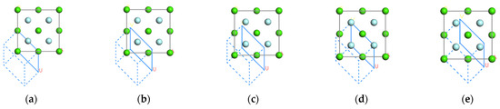
Figure 1.
Atomic structure models for five CaF2(111) crystal faces with different outermost atoms and same surface layer thickness: (a) 0.0, (b) 0.25, (c) 0.5, (d) 0.75, (e) 1.00.
2.1.2. CaF2@SiO2 Crystalline Surfaces at Different Concentrations
In addition, an SiO2 proto-cell model was developed in the visualizer interface. The initial values of the SiO2 lattice constants are set to a = b = c = 7.16 Å and α = β = γ = 90.00°, where the yellow color indicates Si atoms and the red color indicates O atoms. Using the constructed CaF2 model, a spherical CaF2 molecular structure model with a radius of 5 Å is built. An SiO2 model with a radius of 10 Å is built, then the region of the model with a radius of 5 Å is considered, and the selected SiO2 is removed, thus obtaining a toroidal SiO2 model. Combining the spherical CaF2 structural model with a radius of 5 Å with the toroidal SiO2 model yields a radius of 10 Å, with the outermost layer of SiO2 and the inner layer of CaF2 in a spherical model.
To study the effect of CaF2@SiO2 concentration on Si3N4/TiC, three CaF2@SiO2 structural models with different concentrations were developed. For ease of presentation, the three models with different concentrations are denoted by models 6 to 8. CaF2@SiO2 structural models 3, 4, and 5 are placed in models 6, 7, and 8, respectively. Figure 2 shows the initial structural model of CaF2@SiO2.
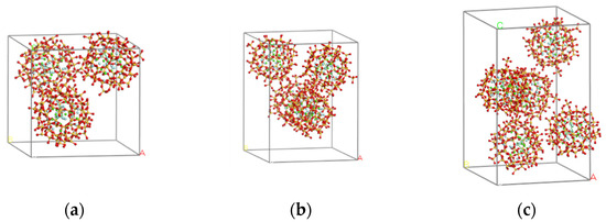
Figure 2.
Initial structure of each model of CaF2@SiO2. (a) model 6, (b) model 7, (c) model 8.
2.1.3. Initial Model of Si3N4/TiC/CaF2
To minimize the mismatch rate, it was necessary to separately expand the crystals. 12 × 3 was chosen for the Si3N4 (110) crystal plane, 12 × 3 for the TiC (100) crystal plane, and 9 × 9 for the CaF2 (111) crystal plane, creating the initial structural model shown in Figure 3.
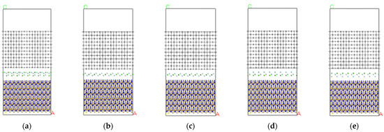
Figure 3.
Initial structure of each Si3N4/TiC/CaF2 model. (a) model 1, (b) model 2, (c) model 3, (d) model 4, (e) model 5.
2.1.4. Initial Model of Si3N4/TiC/CaF2@SiO2
On the 3D modelling platform visualizer, the Si3N4 (110) crystal plane was selected as 12 × 3 for layer 1 of the initial model, the TiC (100) crystal plane was selected as 12 × 3 for layer 3 of the initial model. In addition, the CaF2@SiO2 built in 2.1.2 was used as layer 2, and a 15 Å vacuum layer was added to the upper layer of layer 3. The initial structure of each model is shown in Figure 4.
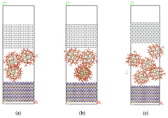
Figure 4.
Initial structure of each Si3N4/TiC/CaF2@SiO2 model. (a) model 6, (b) model 7, (c) model 8.
2.2. Simulation Process
Both materials were calculated using Forcite, the molecular dynamics module of Materials Studio software, with periodic boundary conditions. The model was first optimized for geometry and accuracy with Ultrafine, and then placed in an NVE system with a simulation time of 100 ps. It has been shown that Si3N4 composite ceramic tools have the highest density and best overall mechanical properties at a pressure of 32 MPa. Therefore, 32 MPa was chosen as the sintering pressure in this study [32]. The model was again subjected to molecular dynamics calculations at NPT with a simulation time of 500 ps and temperatures of 1673, 1773, 1873, 1973, and 2073 K. The model was annealed at half the sintering temperature and at 500 K, with a pressure of 0 MPa. The time step was 1 fs and the force field was Universal to the force field (which is detailed by Universal), in order to describe the interaction between the atoms. Finally, the model was analyzed to study its mechanical properties.
2.3. Experimentation
According to the simulation results, the optimum mechanical properties of Si3N4/TiC/CaF2@SiO2 were achieved at a process parameter of 32 MPa and a temperature of 2073 K. Therefore, The Si3N4/TiC/CaF2@SiO2 composite ceramic tool material was prepared experimentally at a pressure of 32 MPa, a temperature of 2073 K, and a holding time of 15 min, with Si3N4/TiC as the base material, CaF2@SiO2 nano-coated particles as the solid lubricant, and Al2O3 and Y2O3 as the sintering aids. The specific grouping of materials is shown in Table 1. The raw material powder used is shown in Table 2.

Table 1.
Material grouping ratios for Si3N4/TiC/CaF2@SiO2 ceramic tools.
Table 2.
Raw materials Si3N4, TiC, Al2O3, Y2O3 CaF2@SiO2.
The preparation process of Si3N4/TiC/CaF2@SiO2 composites is as follows: firstly, the Si3N4, TiC, Al2O3, and Y2O3 powders are weighed, and the measured powders are added to an appropriate amount of anhydrous ethanol for ultrasonic dispersion and stirring, then the components are mixed with continuous ultrasonic stirring. The resulting suspension and the CaF2@SiO2 prepared in advance are poured into a ball mill jar for ball milling, the resulting mixture is placed under a vacuum drying oven for drying, the dried raw material is placed in a sieve and the sieved powder is loaded into a graphite mold for pre-pressing and forming. Finally, it is put into a dual power SPS plasma sintering machine (SPS-625HF) for sintering.
The mechanical properties of the prepared Si3N4/TiC/CaF2@SiO2 composite ceramic tool materials were tested. The hardness was measured using a Vickers hardness tester (Shanghai Taiming Optical Instruments Co., Ltd., Model HVS-30ZC/LCD), the modulus of elasticity was measured using the bending method, and the microstructure of the specimens was observed using a scanning electron microscope (Zeiss, Germany, SUPRA 55).
3. Results and Discussion
3.1. Interfacial Work of Adhesion
3.1.1. Interfacial Adhesion Work of Si3N4/TiC/CaF2
The adhesion work can be used to describe the bonding strength of the interface. The larger the value of its adhesion work, the higher the bonding strength of the interface, and therefore the bonding strengths of the interface can be compared according to the adhesion work. The calculation formula of the adhesion work of the interface of each model is given by:
where is the interface adhesion work, is the energy of Si3N4 that builds the interface, is the energy of TiC that builds the interface, is the energy of the CaF2 that builds the interface, and A is the interface area.
Figure 5 shows the interfacial adhesion work obtained by each model of Si3N4/TiC/CaF2 by molecular dynamics calculation. It can be seen that the interface bonding type also has a great influence on the adhesion work. The adhesion work of each model shows a trend of gradually increasing with the temperature increase. This is because the atoms near the interface gain more energy and get closer to each other through diffusion when the temperature increases. The interactions between these atoms become stronger, and some pairs of atoms create new bonds. The curve shows a linear relationship with the temperature increase.
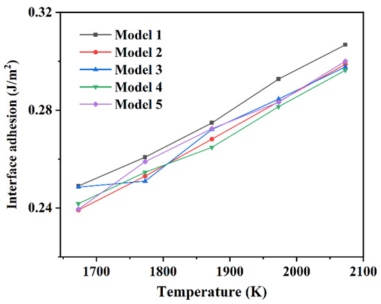
Figure 5.
Interfacial adhesion work of each model of Si3N4/TiC/CaF2.
3.1.2. Interfacial Adhesion Work of Si3N4/TiC/CaF2@SiO2
The interfacial adhesion work of the Si3N4/TiC/CaF2@SiO2 model is computed as:
where is the interfacial adhesion work, is the energy of the Si3N4 building the interface, is the energy of the TiC building the interface, is the energy of the CaF2@SiO2 building the interface, and A is the area of the interface.
Figure 6 shows the interfacial adhesion work of each model of Si3N4/TiC/CaF2@SiO2. It can be seen from Figure 6 that the interfacial adhesion work of each simulation shows a trend of gradually increasing with the temperature increase. The interfacial adhesion work of each model of Si3N4/TiC/CaF2@SiO2 is slightly higher than that of Si3N4/TiC/CaF2 interface adhesion work. It can also be seen that the bonding strength and system stability of the Si3N4/TiC/CaF2@SiO2 interface are stronger than those of Si3N4/TiC/CaF2.
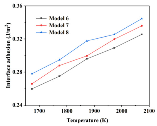
Figure 6.
Adhesion work of each model interface of Si3N4/TiC/CaF2@SiO2.
3.2. Geometry and Interface Analysis
3.2.1. Geometric Structure and Interface Analysis of Si3N4/TiC/CaF2
Table 3, Table 4, Table 5, Table 6 and Table 7 show the model sizes of the Si3N4/TiC/CaF2 models after molecular dynamics calculations. It can be seen that all the models show the phenomenon of shrinkage. Among them, in the a and b directions, the size changes little, while the size decreases in the c direction. The different interface structures constructed by each model lead to different degrees of deformation after molecular dynamics calculation, and the degrees of deformation of α, β, and γ are also different.
Table 3.
Model 1 Dimensions.
Table 4.
Model 2 Dimensions.
Table 5.
Model 3 Dimensions.
Table 6.
Model 4 Dimensions.
Table 7.
Model 5 Dimensions.
Figure 7 shows a cross-sectional view of each model at a temperature of 1873 K after kinetic calculations. It can be seen that the atomic layers at the model interface are displaced to a large extent in the direction perpendicular to the interface, which results in a large change in the size of the model in the c-direction. In addition, a layer misalignment of the atomic layers occurs. It can be seen from Figure 7 that the layer misalignment phenomenon is more pronounced in models 1, 2, and 4. The TiC atomic layer closer to the interface has a larger chirality, the first layer shrinks inwards as a whole, the C-Ti bond length increases, and the C-Ti-C bond angle slightly increases. The second layer is more stable and the atoms away from the interface layer have a smaller relaxation. It can also be deduced that the CaF2 layer as a whole moves closer to the underlying Si3N4 layer, the CaF2 layer and the underlying Si3N4 layer mix with each other, while the CaF2 layer and the upper TiC layer maintain a distance of 3–4 Å. Finally, the layering phenomenon is clear.
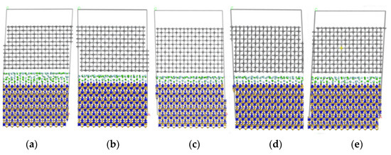
Figure 7.
Final structure of each Si3N4/TiC/CaF2 model. (a) model 1, (b) model 2, (c) model 3, (d) model 4, (e) model 5.
3.2.2. Geometric Structure and Interface Analysis of Si3N4/TiC/CaF2@SiO2
Table 8, Table 9 and Table 10 show the model dimensions after molecular dynamics calculations for models 6 to 8. It can be seen that each model shows shrinkage after the molecular dynamics calculations. In the a direction, each model size increases, while in the b and c directions, each model size contracts, and the contraction in the c direction is more obvious. In the α direction, each model shows an increase, in the β direction, each model has a large change, and in the γ direction, each model undergoes a small change.
Table 8.
Model 6 Dimensions.
Table 9.
Model 7 Dimensions.
Table 10.
Model 8 Dimensions.
Figure 8 shows the cross-section of each model after simulation. It can be seen that the thickness of the vacuum layer in all the models is reduced, the positions of Si3N4 and TiC atoms perpendicular to the interface are greatly changed, and model 6 has a relatively clear deformation. In addition, the CaF2@SiO2 spheres migrated to the lower Si3N4. The relaxation of Si3N4 and TiC atoms near the interface is larger, while the relaxation of Si3N4 and TiC atoms far from the interface is smaller. The first and second layers shrink inward, while the third layer is more stable. In the model, the lower interface of TiC is clearly separated from the middle layer, maintaining the interlayer distance of 2–3 A, while the upper interface of Si3N4 is not clearly stratified with the middle layer. This is due to the fact that the interface of TiC is saturated with Ti-C bond, which has no effect on the interlayer, while the interface of Si3N4 is free N atom and unsaturated Si-N bond, which has a greater impact on the interlayer than the interface of TiC.
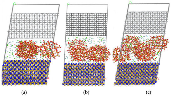
Figure 8.
Final structure of each model of Si3N4/TiC/CaF2@SiO2. (a) model 1, (b) model 2, (c) model 3.
3.3. Mechanical Properties
3.3.1. Mechanical Properties Analysis of Si3N4/TiC/CaF2
The bulk modulus B, shear modulus G, and Young’s modulus E of each Si3N4/TiC/CaF2 model are shown in Figure 9. As the parameter of the outermost vertex of the CaF2 crystalline surface increases from 0.0 to 1.0, the bulk and shear moduli of the corresponding models increase, and the elastic modulus of each model varies with the temperature increase. Among the models, model 1 has the lowest bulk modulus, which indicates that the system is easily compressed. This demonstrates that the model with the outermost vertex parameter (Top) of the crystal plane taking 0 is not conducive to the mechanical properties of the Si3N4/TiC/CaF2 material. In model 5, the material achieves the highest bulk modulus and the strongest average chemical bond, indicating that the system is resistant to deformation. Similarly, the shear modulus and Young’s modulus in model 5 are the highest among the models, which indicates that the system is most resistant to shear deformation.
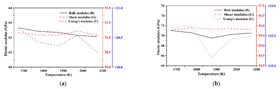
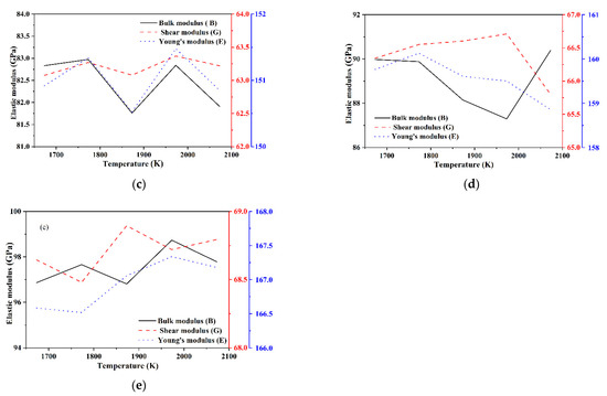
Figure 9.
Elastic modulus of each model of Si3N4/TiC/CaF2. (a) model 1, (b) model 2, (c) model 3, (d) model 4, (e) model 5.
The ratio of bulk modulus B to shear modulus G can be used to measure the ductility and brittleness of a material. A high (low) B/G corresponds to the ductility (brittleness) of the material, and the value used as the dividing node is 1.75. It can be seen from Figure 10 that the B/G ratios of the Si3N4/TiC/CaF2 models calculated in this paper are all below 1.75, ranging from 1.2 to 1.4. This indicates that the molecules of the models are able to calculate the hardness. On the other hand, this is the opposite of the B/G ratio, showing a trend of increasing and then decreasing with the temperature increase, while the hardness attains the highest values at 1873 K and 1973 K. The results show that either too high or too low temperatures have a negative effect on the mechanical properties, and the optimum sintering temperatures are obtained from 1873 K to 1973 K.
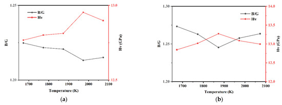
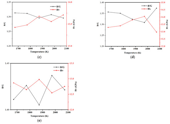
Figure 10.
B/G ratio and hardness of each model of Si3N4/TiC/CaF2. (a) model 1, (b) model 2, (c) model 3, (d) model 4, (e) model 5.
3.3.2. Mechanical Properties Analysis of Si3N4/TiC/CaF2@SiO2
The bulk modulus B, shear modulus G, and Young’s modulus E of each model of Si3N4/TiC/CaF2@SiO2 are shown in Figure 11. The bulk modulus and shear modulus of model 6 and model 7 are significantly higher than those of model 8. In models 6 and 7, the bulk modulus shows an overall tendency to decrease with the temperature increase. In addition, the shear modulus of model 6 fluctuates more with the temperature increase, the Young’s modulus first decreases and then increases, while the shear modulus of model 7 shows an overall tendency to decrease with the temperature increase, and the Young’s modulus gradually decreases. In model 8, the bulk modulus, shear modulus, and Young’s modulus all tend to decrease and then increase with the temperature increase, with the minimum value of bulk modulus being obtained at 1873 K and the minimum values of shear modulus and Young’s modulus being obtained at 1773 K. It can be deduced that the mechanical properties of models 6 and 7 are better than those of model 8.
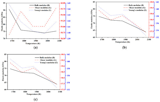
Figure 11.
Elastic modulus of each model of Si3N4/TiC/CaF2@SiO2. (a) model 6, (b) model 7, (c) model 8.
The B/G and hardness Hv of each model of Si3N4/TiC/CaF2@SiO2 are shown in Figure 12. It can be seen that the B/G ratios of each model of Si3N4/TiC/CaF2@SiO2 are all lower than 1.75, indicating that the calculated models belong to brittle materials after molecular dynamics calculation. In models 6 and 7, the hardness shows a tendency to increase with the temperature increase. In model 6, the hardness first rapidly increases and then slowly increases with the temperature increase. The maximum value of hardness is obtained at 2073 K with a value of 13.72 GPa. In model 8, the hardness shows a trend of increasing and then decreasing with the temperature increase. The maximum value of hardness is obtained at 1873 K with a value of 14.13 GPa. In model 7, the hardness first slowly increases and then rapidly increases with the temperature increase, with a maximum value of 15.89 GPa at 2073 K, which is higher than the value in models 6 and 8, where the modulus of elasticity is 132.53 GPa.
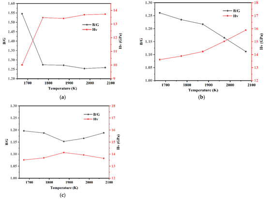
Figure 12.
B/G ratio and hardness of each model of Si3N4/TiC/CaF2@SiO2. (a) model 6, (b) model 7, (c) model 8.
Compared with the Si3N4/TiC/CaF2 simulation system, it can be seen that the addition of the coated structure CaF2@SiO2 to the Si3N4/TiC matrix improves the interface bonding strength and slightly improves the hardness. When the content of CaF2@SiO2 in the model is different, the mechanical properties of the model are also different. At the sintering temperature of 2073 K, when the amount of CaF2@SiO2 is 4, that is, when the proportion of CaF2@SiO2 is 10 vol%, the model hardness reaches the maximum value.
3.4. Phase Analysis and Microstructure of Si3N4/TiC/CaF2@SiO2 Composite Ceramic Material
As can be seen in Figure 13a, as the sintering temperature rises, the sintering agent dissolves into the liquid phase, Si3N4 particles are rearranged in the liquid phase, and ceramic materials increase density. When the temperature reaches a certain degree of formation, some of the α-Si3N4 dissolves into the liquid phase where the solubility is high, and when the saturation of β-Si3N4 is reached, new β-Si3N4 precipitates out of the liquid phase. Finally, the β-Si3N4 grains began to grow and when the sintering temperature reached 1800 °C, Si3N4 reacted with TiC to form SiC and TiC0.7N0.3 in.
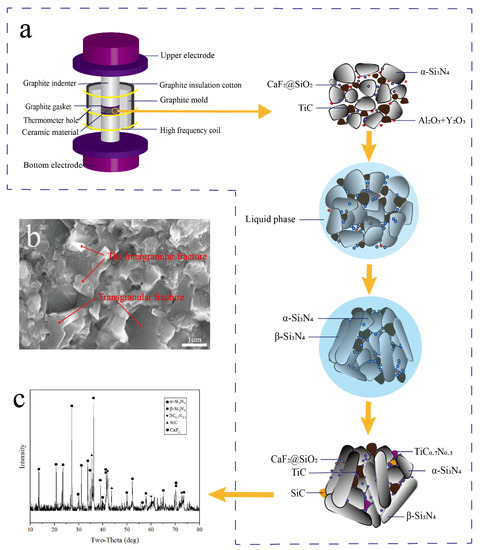
Figure 13.
Process diagram of Si3N4/TiC/CaF2@SiO2 ceramic tool in discharge plasma sintering. (a) SPS process of sintering ceramic tool material, (b) the microstructure of the material after sintering, (c) XRD pattern of the tool material after sintering.
The fracture SEM photographs and energy spectra of the Si3N4/TiC/CaF2@SiO2 composite ceramic tool material are shown in Figure 13b. It can be seen from the SEM photographs in Figure 13c that the material is densely sintered with no obvious porosity. The Si3N4/TiC/CaF2@SiO2 composite ceramic material has two different fracture modes (along-crystal fracture and through-crystal fracture), contributing to the mechanical properties.
The prepared Si3N4/TiC/CaF2@SiO2 composite ceramic tool material was selected as the specimen for XRD analysis. It can be seen from Figure 13 that the diffraction peaks of α-Si3N4 and β-Si3N4 are very clear as the main crystalline phases. Diffraction peaks of SiC and TiC0.7N0.3 can also be clearly observed.
3.5. Mechanical Properties of Si3N4/TiC/CaF2@SiO2 Composite Ceramic Tool Materials
The mechanical properties of the sintered Si3N4/TiC/CaF2@SiO2 composite ceramic tool material were tested with a hardness of 15.66 GPa and a modulus of elasticity of 128.08 GPa. The results of the comparison between the simulated and experimental values are shown in Table 11. It can be seen that the simulated and experimental values are consistent.
Table 11.
Simulated and experimental values of the mechanical properties of Si3N4/TiC/CaF2@SiO2 composite ceramic materials.
4. Conclusions
As the addition of solid lubricants can improve the mechanical properties of ceramic materials, this paper studies the effect of CaF2 and CaF2@SiO2 addition on Si3N4/TiC materials using molecular dynamics. Different CaF2 and CaF2@SiO2 models were developed to analyze the effects on the material interface as well as the mechanical properties. Based on the simulation results, the optimum sintering parameters for the Si3N4/TiC/CaF2@SiO2 material were obtained: a temperature of 2073 K at a pressure of 32 MPa. Based on these sintering parameters, the Si3N4/TiC/CaF2@SiO2 composite ceramic tool material was experimentally prepared and the mechanical properties were tested.
(1) The interfacial atomic layer is displaced to a greater extent in the direction perpendicular to the interface, and the atomic layer undergoes a phenomenon of layer dislocation. The TiC atomic layer closer to the interface has a larger amount of chirality, the first layer shrinks inwards as a whole, the C-Ti bond length increases, and the C-Ti-C bond angle slightly increases.
(2) When the type of atomic bonding at the interface between CaF2 and the Si3N4 and TiC models is different, the corresponding elastic constants and elastic moduli are also different. The addition of CaF2 leads to a decrease in the hardness of the system.
(3) The mechanical properties of the Si3N4/TiC/CaF2@SiO2 models differed when CaF2@SiO2 was added in different amounts. The model achieved optimum mechanical properties when the addition of CaF2@SiO2 in the model was 4. The hardness of the material increased with the temperature increase. It was 15.89 GPa when the temperature was 2073 K, while the modulus of elasticity was 132.53 GPa.
(4) The Si3N4/TiC/CaF2@SiO2 composite ceramic tool material was experimentally prepared with mechanical properties of 15.66 GPa hardness and 128.08 GPa modulus of elasticity, that are slightly lower than the simulated values. The SEM photograph at the fracture shows a mixed mode of along-crystal fracture and through-crystal fracture, which contributes to the mechanical properties.
Author Contributions
Conceptualization, G.X. and Z.C.; methodology, Z.C., Q.L. and X.L.; validation, Q.L. and X.L.; formal analysis, X.L.; investigation, Z.C.; resources, M.Y.; data curation, X.L.; writing—original draft preparation, Q.L. and X.L.; writing—review and editing, G.X. and Z.C.; visualization, T.Z., J.Z. and H.C.; supervision, C.X.; project administration, C.X.; funding acquisition, Z.C. All authors have read and agreed to the published version of the manuscript.
Funding
This work is financially supported by the Shandong Province Key Research and Development Plan (grant number 2020CXGC011004); the Natural Science Foundation of Shandong Province (grant number ZR2020ME155); the National Natural Science Foundation of China (grant number 52075276).
Data Availability Statement
Not applicable.
Acknowledgments
Thanks to the co-authors of this paper for their help, the editors and reviewers for their valuable revisions, and the institutions and individuals not mentioned who provided assistance for this study.
Conflicts of Interest
We declare no conflict of interest.
References
- Šajgalik, P.; Dusza, J.; Hoffmann, M.J. Relationship between Microstructure, Toughening Mechanisms, and Fracture Toughness of Reinforced Silicon Nitride Ceramics. J. Am. Ceram. Soc. 1995, 78, 2619–2624. [Google Scholar] [CrossRef]
- Bitterlich, B.; Bitsch, S.; Friederich, K. SiAlON based ceramic cutting tools. J. Eur. Ceram. Soc. 2008, 28, 989–994. [Google Scholar] [CrossRef]
- Tan, D.-W.; Zhu, L.-L.; Wei, W.-X.; Yu, J.-J.; Zhou, Y.-Z.; Guo, W.-M.; Lin, H.-T. Performance improvement of Si3N4 ceramic cutting tools by tailoring of phase composition and microstructure. Ceram. Int. 2020, 46, 26182–26189. [Google Scholar] [CrossRef]
- Lin, H.-B.; Cao, M.-S.; Zhao, Q.-L.; Shi, X.-L.; Wang, D.-W.; Wang, F.-C. Mechanical reinforcement and piezoelectric properties of nanocomposites embedded with ZnO nanowhiskers. Scr. Mater. 2008, 59, 780–783. [Google Scholar] [CrossRef]
- Zou, B.; Huang, C.; Chen, M.; Gu, M.; Liu, H. Study of the mechanical properties, toughening and strengthening mechanisms of Si3N4/Si3N4w/TiN nanocomposite ceramic tool materials. Acta Mater. 2007, 55, 4193–4202. [Google Scholar] [CrossRef]
- Zhao, J.; Ai, X.; Lu, Z. Preparation and characterization of Si3N4/TiC nanocomposite ceramics. Mate Lett. 2006, 60, 2810–2813. [Google Scholar] [CrossRef]
- Nguyen, V.-H.; Namini, A.S.; Delbari, S.A.; Van Le, Q.; Asl, M.S.; Shokouhimehr, M.; Mohammadi, M. A survey on spark plasma sinterability of CNT-added TiC ceramics. Int. J. Refract. Met. Hard Mater. 2021, 96, 105471. [Google Scholar] [CrossRef]
- Zou, B.; Huang, C.; Song, J.; Liu, Z.; Liu, L.; Zhao, Y. Mechanical properties and microstructure of TiB2–TiC composite ceramic cutting tool material. Int. J. Refract. Met. Hard Mater. 2012, 35, 1–9. [Google Scholar] [CrossRef]
- Xing, H.; Liu, B.; Sun, J.; Zou, B. Mechanical properties of Si3N4 ceramics from an in-situ synthesized a-Si3N4/β-Si3N4 composite powder. Ceram. Int. 2017, 43, 2150–2154. [Google Scholar] [CrossRef]
- Suarez, M.P.; Marques, A.; Boing, D.; Amorim, F.L.; Machado, R. MoS2 solid lubricant application in turning of AISI D6 hardened steel with PCBN tools. J. Manuf. Process. 2019, 47, 337–346. [Google Scholar] [CrossRef]
- Zhao, Y.; Feng, K.; Yao, C.; Nie, P.; Huang, J.; Li, Z. Microstructure and tribological properties of laser cladded self-lubricating nickel-base composite coatings containing nano-Cu and h-BN solid lubricants. Surf. Coatings Technol. 2018, 359, 485–494. [Google Scholar] [CrossRef]
- Essa, F.; Zhang, Q.; Huang, X. Investigation of the effects of mixtures of WS2 and ZnO solid lubricants on the sliding friction and wear of M50 steel against silicon nitride at elevated temperatures. Wear 2017, 374–375, 128–141. [Google Scholar] [CrossRef]
- Deng, J.; Cao, T. Self-lubricating mechanisms via the in situ formed tribofilm of sintered ceramics with CaF2 additions when sliding against hardened steel. Int. J. Refract. Met. Hard Mater. 2007, 25, 189–197. [Google Scholar] [CrossRef]
- Wu, G.; Xu, C.; Xiao, G.; Yi, M.; Chen, Z. Structure design of Al2O3/TiC/CaF2 multicomponent gradient self-lubricating ceramic composite and its tribological behaviors. Ceram. Int. 2018, 44, 5550–5563. [Google Scholar] [CrossRef]
- Xu, C.; Wu, G.; Xiao, G.; Fang, B. Al2O3/(W,Ti)C/CaF2 multi-component graded self-lubricating ceramic cutting tool material. Int. J. Refract. Met. Hard Mater. 2014, 45, 125–129. [Google Scholar] [CrossRef]
- Wang, N.; Wang, H.; Ren, J.; Gao, G.; Zhao, G.; Yang, Y.; Wang, J.; Yang, S. A case study of PTFE@SiO2 core-shell solid lubricant. Tribol. Int. 2021, 160, 107016. [Google Scholar] [CrossRef]
- Wu, B.; Song, H.; Zhang, Q.; Hu, X. Controllable synthesis and friction reduction of ZnFe2O4@C microspheres with diverse core-shell architectures. Tribol. Int. 2020, 153, 106614. [Google Scholar] [CrossRef]
- Lv, J.; Cui, C.; Chen, S.; Cui, S.; Ding, J.; Liu, S. Microstructure evolution and mechanical properties of Ti–46Al–4Nb alloy modified by in-situ Si3N4-graphene core-shell nanoparticles. Mater. Sci. Eng. A 2020, 785, 139349. [Google Scholar] [CrossRef]
- Chen, Z.; Ji, L.; Guo, R.; Xu, C.; Li, Q. Mechanical properties and microstructure of Al2O3/TiC based self-lubricating ceramic tool with CaF2@Al (OH)3. Int. J. Refract. Met. Hard Mater. 2019, 80, 144–150. [Google Scholar] [CrossRef]
- Chen, Z.; Guo, N.; Ji, L.; Guo, R.; Xu, C. Influence of CaF2@Al2O3 on the friction and wear properties of Al2O3/Ti(C,N)/CaF2@Al2O3 self-lubricating ceramic tool. Mater. Chem. Phys. 2018, 223, 306–310. [Google Scholar] [CrossRef]
- Wu, G.; Xu, C.; Xiao, G.; Yi, M.; Chen, Z.; Xu, L. Self-lubricating ceramic cutting tool material with the addition of nickel coated CaF2 solid lubricant powders. Int. J. Refract. Met. Hard Mater. 2016, 56, 51–58. [Google Scholar] [CrossRef]
- Wu, G.; Xu, C.; Xiao, G.; Yi, M.; Chen, Z.; Chen, H. An advanced self-lubricating ceramic composite with the addition of core-shell structured h-BN@Ni powders. Int. J. Refract. Met. Hard Mater. 2018, 72, 276–285. [Google Scholar] [CrossRef]
- Chen, Z.; Guo, N.; Ji, L.; Xu, C. Synthesis of CaF2 Nanoparticles Coated by SiO2 for Improved Al2O3/TiC Self-Lubricating Ceramic Composites. Nanomaterials 2019, 9, 1522. [Google Scholar] [CrossRef]
- Minatto, F.D.; Milak, P.; De Noni, A.; Hotza, D.; Montedo, O.R.K. Multilayered ceramic composites—A review. Adv. Appl. Ceram. 2014, 114, 127–138. [Google Scholar] [CrossRef]
- Sazgar, A.; Movahhedy, M.; Mahnama, M.; Sohrabpour, S. A molecular dynamics study of bond strength and interface conditions in the Al/Al2O3 metal–ceramic composites. Comput. Mater. Sci. 2015, 109, 200–208. [Google Scholar] [CrossRef]
- Shen, Y.; Mi, S.; Sun, L.; Yang, L.; Gong, H. Mechanical properties and dislocation evolution of Cu-Fe interfaces from molecular dynamic simulation. Mater. Chem. Phys. 2021, 262, 124270. [Google Scholar] [CrossRef]
- Zhou, T.T., Huang, C.Z., Liu, H.L., Zou, B., Zhu, H.T., Eds.; Molecular Dynamics Simulation of Al2O3-SiC Interface. In Proceedings of the 14th International Manufacturing Conference in China, Tianjin, China, 13–15 October 2011. [Google Scholar] [CrossRef]
- Wang, X.; Zhao, J.; Cui, E.; Liu, H.; Dong, Y.; Sun, Z. Effects of sintering parameters on microstructure, graphene structure stability and mechanical properties of graphene reinforced Al2O3-based composite ceramic tool material. Ceram. Int. 2019, 45, 23384–23392. [Google Scholar] [CrossRef]
- Zhang, J.; Zhu, T.; Sang, S.; Li, Y.; Pan, L.; Liao, N.; Liang, X.; Wang, Q.; Xie, Z.; Dai, J. Microstructural evolution and mechanical properties of ZrO2(3Y)–Al2O3–SiC(w) ceramics under oscillatory pressure sintering. Mater. Sci. Eng. A 2021, 819, 141445. [Google Scholar] [CrossRef]
- Fang, B.; Huang, C.-Z.; Xu, C.-H.; Sun, S. Numerical simulation of microstructural evolution of ceramic tool materials. Comput. Mater. Sci. 2008, 44, 707–715. [Google Scholar] [CrossRef]
- Hao, S.; Huang, C.; Zou, B.; Wang, J.; Liu, H.; Zhu, H. Three dimensional simulation of microstructure evolution for ceramic tool materials. Comput. Mater. Sci. 2011, 50, 3334–3341. [Google Scholar] [CrossRef]
- Bai, X.; Huang, C.; Wang, J.; Zou, B.; Liu, H. Sintering mechanisms of Al2O3-based composite ceramic tools having 25% Si3N4 additions. Int. J. Refract. Met. Hard Mater. 2018, 73, 132–138. [Google Scholar] [CrossRef]
Disclaimer/Publisher’s Note: The statements, opinions and data contained in all publications are solely those of the individual author(s) and contributor(s) and not of MDPI and/or the editor(s). MDPI and/or the editor(s) disclaim responsibility for any injury to people or property resulting from any ideas, methods, instructions or products referred to in the content. |
© 2023 by the authors. Licensee MDPI, Basel, Switzerland. This article is an open access article distributed under the terms and conditions of the Creative Commons Attribution (CC BY) license (https://creativecommons.org/licenses/by/4.0/).