Abstract
The review starts by highlighting the significance of nuclear power plants in the contemporary world, especially its indispensable role in the global efforts to reduce CO2 emissions. Then, it describes the impact of irradiation on the microstructure and mechanical properties of reactor structural materials. The main part provides the reader with a thorough overview of crystal plasticity models developed to address the irradiation effects so far. All three groups of the most important materials are included. Namely, the Zr alloys used for fuel cladding, austenitic stainless steels used for reactor internals, and ferritic steels used for reactor pressure vessels. Other materials, especially those considered for construction of future fission and fusion nuclear power plants, are also mentioned. The review also pays special attention to ion implantation and instrumented nanoindentation which are common ways to substitute costly and time-consuming neutron irradiation campaigns.
1. Introduction
Climate scientists report extremely fast gobal warming as a result of enormous CO2 emissions. The rate of this change seems to be too fast to be manageable by most of the flora and fauna species as well as modern human civilizations. Therefore, it is important to introduce emission-free energy sources [1]. Although solar and wind power plants are paid much attention to, they cannot play a dominant role yet as they are not sufficiently stable and large-scale storage of electrical energy is still an unsolved problem. Moreover, they require extremely large usage of land in order to fulfil country-scale energy needs and the rate of installing new power plants is not satisfactory. That is why at least some part of the energy should come from nuclear power plants (NPPs) if CO2 emissions are to be reduced quickly. It should be also mentioned that apart from being emission-free, NPPs offer further advantages, such as an extremely low amount of fuel (as compared to fossil fuel power plants), which offers the possibility to store the fuel for many years of operation in advance, thus being independent from unstable political situations across the world; extremely low amounts of waste (as compared to fossil fuel power plants); stable electrical energy generation (also heat generation if cogeneration is considered); and extremely low usage of land (especially as compared to solar, wind and water power plants).
The important materials used in currently operating NPPs are The pressurized water reactors (PWRs, cf. [2]) are considered here, as they are the most commonly operated NPPs.:
- Zirconium alloys having hexagonal close-packed (HCP) lattices. They are used for fuel cladding and thus are subjected to the highest radiation. On the other hand, they have to survive only during the time between subsequent fuel replacements (typically around 6 years).
- Austenitic stainless steels (ASS) having face-centred cubic (FCC) lattices. They are used for reactor vessel internals, which fulfil many functions such as supporting the core, control rod assemblies, core support structure, and reactor pressure vessel (RPV) surveilance capsules [3]. As they are inside the RPV, they are subjected to considerable neutron fluxes,
- Ferritic steels of body centred cubic (BCC) lattice, such as e.g., US A508C1 or A533B, French 16MnD5, Russian 15Cr2MoVA, and Chinese A508-3 steels, are used to build reactor pressure vessels. As the vessel is typically very large and has very thick walls, it is in principle the only part that cannot be replaced. Thus, its lifetime determines the service lifetime of the whole NPP.
As will be seen in the following, most models developed so far have dealt with materials belonging to one of those three groups. The studies are driven by practical considerations such as, e.g., answering the question of RPV life extension [4]. The assessment of irradiation-induced effects on the mechanical properties of construction materials in NPPs is crucial as it is strongly related to safety of the unit. Although the irradiation typically leads to increasing the yield strength of the material, it often also results in post-yield softening, decrease in ductility, and increase in ductile to brittle transition temperature (DBTT). Other important phenomena are the swelling and irradiation growth of the fuel cladding. Therefore, reliable, physically sound, and experimentally consistent material models should be built in order to address those issues.
Although presently built generation III/III+ NPPs are much improved as compared to previous projects, generation IV (Gen-IV) initiative calls for new nuclear energy systems that will significantly improve the safety and reliability, sustainability, useful reactor life, proliferation-resistance, and profitability [5]. Generation-IV International Forum (GIF) members identified six systems [6]: very high temperature gas-cooled reactors (VHTR) [7,8], gas-cooled fast reactors (GFR) [9], sodium-cooled fast reactors (SFR) [10,11], lead-cooled fast reactors (LFR) [12], molten salt reactors (MSR) [13], and super-critical water-cooled reactors (SCWR) [14]. However, the Gen-IV projects typically pose new material challenges. Depending on the particular reactor type, the construction materials have to typically sustain (as compared to existing NPPs):
- Longer operation times;
- Higher radiation doses;
- Higher operating temperatures (especially in the case of VHTR);
- More chemically aggressive environments.
Moreover, in the case of future fusion reactors, even higher radiation and temperature are expected.
Therefore, for future generation IV NPPs, in general, different materials should be used, as outlined in [5,15]. Among the class of metallic materials, four types of steels, namely ferritic–martensitic (FM), austenitic stainless, and oxide-dispersion-strengthened (ODS) steels (cf. [16]) are enlisted as promising candidates. ODS steels with FM matrices were designated as those that enable achieving the high radiation doses and high burn-ups required in fast reactors. Nickel-based alloys also make an important class of materials, especially in the case of very high temperature reactors. Specifically, none of the steels are considered as suitable for VHTRs, except the ferritic–martensitic steels which are considered as a secondary option. In the case of future fusion power plants, especially harsh conditions are expected in the case of plasma-facing components. Tungsten has a high melting point, low rate of tritium retention, low rate of sputtering, and good thermal conductivity [17]. Therefore, tungsten-based materials, e.g., tungsten-based high-entropy alloys [18,19] are considered for this particular application. Due to its excellent properties at high temperature, Mo is also considered as a candidate material for a divertor in a fusion reactor [20].
2. Irradiation-Induced Effects
Irradiation leads to changes in the microstructure [21,22,23,24,25,26] and mechanical properties [27] of materials. The basic mechanism responsible for those changes can be found in, e.g., [28,29] and references therein. An energetic particle (neutron in the case of nuclear reactor, ion in the case of ion implantation experiment) collides with an atom present in crystalline structure of a given metallic material. This collision results in displacing a so-called primary knock-on atom (PKA). This atom then interacts with other atoms, leading to a cascade of defects occurring in the material. Vacancy-interstitial pairs are thus created. They can then reconfigure, leading to creation of defects such as stacking fault tetrahedra (SFT) in FCC lattice or dislocation loops (DLs) in BCC lattice (see Figure 1). The problem is even more complicated in HCP Zr alloys where interstitial-type DLs are formed on prismatic planes and vacancy-type DLs on basal ones [30]. Huge amounts of irradiation-induced vacancies lead to formation of voids in the material which can be macroscopically identified as swelling. Other defects, such as precipitates or solute rich clusters (SRCs) [31], can be also created. In the case of RPV steels, nucleation and growth of Cu, Ni, and Mn precipitates due to irradiation are important issues [32]. According to the dispersed barrier hardening (DBH) model [33], defects impede the movement of dislocations, thus leading to irradiation hardening.
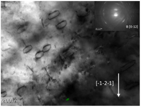
Figure 1.
Dislocation loops in irradiated pure iron visible in TEM micrograph [34].
A common feature of irradiated materials is also the appearance of defect-free channels (see Figure 2) accompanied by macroscopically observed post-yield softening and ductility loss (see Figure 3; see also [35]). There seems to be a scientific consensus that the channels originate from local annihilation of irradiation-induced defects by gliding dislocations. This drives localization and softening. In the course of further deformation, nucleation, growth, and coalescence of voids occur at the intersection of soft channels with hard material. This can finally lead to fracture. Apart from the neutron–PKA interaction, other mechanisms are possible. For example, a nuclear reaction of a given atom with incoming neutron can lead to its transmutation. The Al-Si transmutation in Al-6061 alloy leads to formation of Si precipitates [36]. The other effect is the generation of He through the (n, α) nuclear reaction. Huge amounts of generated He can lead to formation of He bubbles; see Figure 4. Yet another important phenomenon is irradiation-induced grain boundary segregation [37], which can lead to brittle fracture. Sometimes, irradiation can also lead to recrystallization [38].
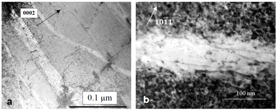
Figure 2.
(a) Dislocation channels in irradiated and tension-deformed Zircaloy-2, (b) dislocations and dislocation loops within the channel [39].
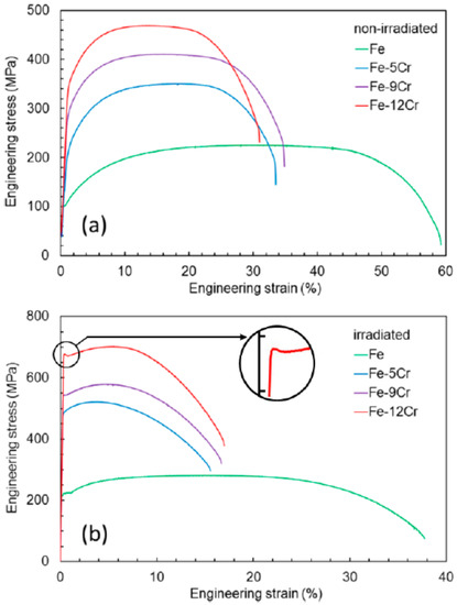
Figure 3.
Engineering stress strain curves in iron and iron-chromium alloys in (a) virgin and (b) irradiated state [40]. Post-yield softening and ductility loss are clearly observed in the irradiated case.
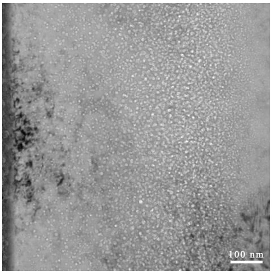
Figure 4.
He bubbles in FeCrNi alloy subjected to He implantation seen as bright regions in TEM micrograph [41].
The amount of neutrons of a given energy flowing through the material can be characterized by their fluence , which is equal to the number of neutrons penetrating the sphere having the cross section :
However, from the point of view of mechanics and materials science, the displacement per atom (dpa) [42] provides a better measure of the effects of irradiation on material, as it does not depend on energetic spectrum of neutrons [43] and can be also applied to ions. In order to calculate dpa in the case of ion irradiation, SRIM software [44] is commonly used. Recently, the Iradina code [45] was developed. According to its developers, it offers some advantages over the SRIM software.
3. Modelling Irradiation Effects
There have so far been many efforts to take into account the influence of irradiation defects on the mechanical properties of metals and alloys in macroscopic phenomenological models; see, e.g., [46,47,48,49,50,51]. However, as could be seen from the previous paragraphs, the phenomena related to radiation-induced microstructure changes appear at different time and length scales, and therefore a multiscale modelling approach is the most appropriate in addressing them [27,32]. The fundamental mechanisms and their energetics can be obtained from atomic scale methods, such as molecular dynamics or even ab initio. Larger volumes and longer times can be achieved using coarse-grained methods such as kinetic Monte Carlo or dislocation dynamics, utilizing information gained from atomistic modelling. The next scale is the meso scale that forms a bridge between discrete and continuum models. Apart from phase field and cluster dynamics, such an approach is the crystal plasticity theory, which is the topic of this review. Readers interested in links between atomistic simulations and constitutive models of irradiated materials are referred to another review [27].
CP predictions can be both directly utilized to obtain macroscopic response of a specimen as well as used to gain insight into grain-scale phenomena. The CP theory is particularly useful in the context of modelling the effect of irradiation. First, it enables to reproduce experimentally observed irradiation hardening and post-yield softening by realistically accounting for dislocation-defect interactions [28]. Second, using CP, one can directly compute stress distributions arising due to grain size, crystallographic orientation, and other microstructural effects. These distributions can be then used to provide data for probabilistic assessment of brittle fracture [52,53]. Third, one can study the microcrack nucleation at intersections of grain boundaries and dislocation channels [54]. Fourth, it is possible to investigate in detail the effect of interactions on void growth and coalescence [55]. In general, the crystal plasticity can be crudely divided into so-called phenomenological crystal plasticity (PCP) and dislocation density based crystal plasticity (DDCP) theories. In PCP, the critical resolved shear stress (CRSS) evolves with the amount of accumulated slip, while in DDCP it is related to the evolving dislocation densities.
3.1. Materials for Fuel Cladding
In the PCP model of Deo et al. [56], the CRSS is increased according to the formula (cf. [47]):
where is the initial CRSS, is the unirradiated CRSS, is the defect cluster barrier strength, is the shear modulus, b is the Burgers vector length, N is the defect cluster density, and d is their diameter.
In the paper of Onimus and Béchade [57], the crystal plasticity theory was applied to model the behaviour of irradiated zirconium alloy of HCP crystallographic structure. Irradiation hardening was incorporated by modifying the CRSS, similarly as in [56]. However, population of dislocation loops evolved with accumulated slip. In addition, the fact that interaction between dislocation loops and mobile dislocations is different for different slip system families was taken into account. Dislocation channelling was also considered.
Irradiated ziracalloy was also analysed in [58]. The irradiation effect was introduced in a similar fashion to the previous papers. Softening was taken into account by decreasing the CRSS of basal and prismatic slip after reaching the critical value of slip. Using the model combined with FEM homogenization, it was possible to simulate strain localization, softening, and associated ratcheting in irradiated zircalloy subjected to cyclic loading.
Thermal creep, irradiation creep, and irradiation-induced growth were taken into account in the constitutive model reported in [59]. Two micro–macro transition schemes enabling to obtain the response of the polycrystal from the single crystal consistutive model were compared, namely the self-consistent method and FFT solver AMITEX_FFTP.
Crystal plasticity finite element method (CPFEM) was used to perform the modelling of neutron-irradiated Zircaloy-4 [60]. Accounting for the presence of irradiation-induced dislocation loops (leading to irradiation hardening) and their annihilation due to gliding dislocations (leading to softening) made it possible to reproduce the macroscopic stress–strain response of the material. Additionally, Jose et al. [61] used CPFEM to study neutron-irradiated Zircaloy-4. In addition to accounting for the presence of irradiation-induced defects and their annihilation, a model of damage by void growth was introduced. Contrary to other models for Zr, both [60,61] applied a thermal activation flow rule (cf. Equation (4)) in their studies.
3.2. Model FCC Materials
Pure FCC metals do not have practical importance in nuclear power engineering. However, they serve as an excellent model material to study the effect of irradiation. Therefore, Krishna et al. [28] developed the crystal plasticity model for FCC copper. The model seems to be the first one tracking both the evolution of dislocation and defect densities. Dislocation populations on each slip system were taken into account. Additionally, the defects (SFTs) for each slip system were accounted for. Such an approach allowed to successfully capture increase in yield stress followed by yield drop and non-zero stress offset from the un-irradiated stress–strain curve. Capturing these phenomena was possible due to the interplay of dislocation density evolution (two terms—growth and dynamic recovery) and defect annihilation due to interaction with dislocations. The critical resolved shear stress was calculated using the equation:
where is a statistical parameter, G is the shear modulus, is the Burgers’ vector in the slip plane, and are interaction matrices, and and are densities of dislocations and defects, respectively. Similar equations were used in most of the subsequent crystal plasticity studies cited in this review. However, when it comes to coupling dislocation and defect terms, sometimes the sum of square roots (linear superposition) was used instead of the square root of sums. The issue of choosing the right superposition rule was thoroughly discussed in [27,43]. Additionally, latent hardening introduced by means of interaction matrices was sometimes neglected.
A crystal plasticity model accounting for irradiation-induced changes was also developed by Xiao et al. In [62], the model for FCC single crystal was presented. One of its crucial aspects is accounting for dislocation-defect interaction in a tensorial fashion. To this aim, the equations developed in [63] and enhanced by adding the annihilation probability term developed in [28] were applied. This was performed in order to account for the different nature of the most important defects. Barton et al. (see Section 3.4) dealt with irradiated BCC material where the dislocation loops are common. In the case of FCC copper, SFTs are the major irradiation-induced defects. Since they are 3D objects, their interaction with dislocations is different than in the case of DLs. The evolution of dislocation density on each slip system has just two terms accounting for storage and dynamic recovery. In [64] the model was further enhanced by accounting for temperature and implemented in the elastic-viscoplastic self-consistent (EVPSC) model. Using the self-consistent model based on [65] enabled to model the response of a polycrystalline material.
A model for FCC metals was also presented in [66]. The model is quite similar to [67] (described in Section 3.4), but contrary to op. cit., where the mobile and immobile dislocation densities were tracked separately; here, edge and screw dislocation populations were divided. Since the SFTs are basic irradiation-induced defects in FCC metals, the defect evolution model based on [28] was applied. In [68], stochasticity was introduced in the CP by accounting for distribution of CRSS. The approach of Barton et al. [63] was applied to account for interactions of dislocations with SFTs. The model enabled the generation of dislocation channel (DC) structures in irradiated single and polycrystalline copper. Post-yield softening was also reproduced.
3.3. Materials for Reactor Internals
Intergranular stress corrosion cracking (IGSCC) and in particular irradiation-assisted stress corrosion cracking (IASCC) phenomena were observed in reactor internals made of austenitic stainless steel. Therefore, in [54], a single DC interfacing a grain boundary was analysed using CPFEM simulation. Irradiation was not taken into account directly as the DC was considered to be already free of irradiation defects (note, however, that DC itself is a result of irradiation followed by mechanical deformation). The results were used to build an analytical model and deduce a microcrack nucleation criterion.
A model for irradiated ASS was introduced in [69,70]. The hardening law of the crystal plasticity model was enriched by incorporating the effects connected with the emergence of Frank loops and dislocation unlock. The main conceptual difference of this model with respect to other approaches stems from the fact that instead of supplying the initial defect densities (measured or calculated in lower scale models), a different set of material parameters is needed for each level of dpa. The model was originally implemented in ZéBuLoN and Cast3M finite element method programs. In [71], its implementation into the more commonly used ABAQUS FEM software was described in detail. Additionally, the validation on simplified microstructures was presented. In [72], the parameter calibration was performed and the necessary number of grains and finite elements per grain were investigated. The model developed in the cited papers was then applied in [73] to evaluate influence of irradiation on IGSCC. The developed model was also applied in [55] to study the effect of irradiation up to 13 dpa on the growth and coalescence of voids in FCC single crystals. The authors carried out CPFEM simulations of single crystals with voids whose size corresponded to secondary voids resulting from high irradiation levels. The results of simulations enabled to conclude that in materials subjected to irradiation voids grow faster and coalesce earlier because of more significant plastic slip localization. The irradiated material tends to suffer from macroscopic embrittlement even though fine dimples at the failure site characteristic for ductile failure can be observed. This seemingly paradoxical behaviour can be well explained using the authors’ conclusions. El Shawish et al. [3] applied the developed model to investigate tensile response of the austenitic stainless steel SA304L irradiated to 0.8 dpa. The model of [69] was also used as a benchmark for validating the analytical model of neutron-irradiated austenitic steel in [74]. In addition, the crystal plasticity model implementation using fast Fourier transforms (FFT) in the CraFT software was presented there. The results of CP simulations were compared against the experimental data from Russian austenitic steels irradiated in fast reactors. IGSCC in irradiated ASS was also the subject of [75].
The model for FCC austenitic stainless steels was presented in [76]. The contributions to CRSS arising from dislocation forest, DLs, and SRCs are combined using the quadratic sum. On the other hand, friction due to solid solution and the Hall–Petch effect are included by linear superposition. Dislocation population evolves separately on each slip system, while the DLs and SRCs are assumed to be uniformly distributed. The polycrystalline behaviour was obtained by implementing the model in the elasto-plastic self-consistent (SC) model of Berveiller and Zaoui (BZ) [77]. Additionally, an analytical model for yield stress prediction was presented. The authors adjusted the set of parameters to obtain the stress strain curve of un-irradiated material. The response of irradiated material was simulated to be in reasonable agreement with experimental data by proper selection of DL density and a parameter accounting for annihilation of radiation defects by moving dislocations. The effect of SRCs was disregarded at the validation stage.
3.4. Materials for Reactor Pressure Vessel
Structural materials for reactor pressure vessels are various types of BCC ferritic–martensitic low-alloyed steels (see the Introduction for the types used in various countries). However, while some authors develop models for the particular RPV steel, the others prefer to keep the problem as simple as possible by working with pure BCC metals or model alloys. The subsection covers both types of approaches.
The DDCP model was used to simulate behaviour of 22NiMoCr37 RPV steel in [52]. Classically, CP formulations use power law ([78]; see also [79,80,81,82]) of the type:
where is the slip rate on system , is the reference slip rate, is the crtical resolved shear stress, m is the rate sensitivity, and is the resolved shear stress (RSS). However, since this simplified description is not able to capture the real strain rate and temperature sensitivity of plastic flow [83] and does not account for the inherent lattice resistance in BCC metals [47], in [52] (and many other DDCP models cited in this review) the thermal activation Kocks-type plastic flow law [84] similar to the one presented in [83] was applied:
where can be calculated based on dislocation theory [85] or selected as a material parameter, is the activation free energy required to overcome obstacles to slip without the aid of an applied shear stress, is the Boltzmann’s constant, p and q are exponents that should lie in the range (0,1) and (1,2), respectively. According to [83], , and denotes the part of the resistance due to athermal obstacles to slip (those that cannot be overcome with the aid of thermal fluctuations, such as dislocation groups and large incoherent particles). represents the part due to thermal obstacles (those that can be overcome with the aid of thermal fluctuations, such as the Peierls resistance, solute atoms, and forest dislocations). Evolution of dislocation densities on each slip system was tracked using two terms, namely the storage dependent on mean free path and the annihilation distance. Irradiation was introduced by modifying the initial value of CRSS without explicitly accounting for irradiation-induced defects. However, the paper presented quite detailed analysis of simulation results as concerns probabilistic assessment of brittle fracture.
A very detailed crystal plasticity constitutive model of irradiated BCC material was presented in [29]. The model accounts for number density and mean size of the dislocation loops. However, for simplicity, only interstitial loops are taken into account since the vacancy loops are smaller and they do not impede the glide of dislocations considerably. The mobile and immobile dislocation densities were tracked separately on each of 48 slip systems. Various physical phenomena are separately included in the evolution laws. The evolution of the concentrations of irradiation-induced point defects (separately for interstitials and vacancies) is also taken into account. The authors also proposed the phenomenological rule for a rate of annihilation of immobile dislocations and interstitial loops. The rate of shearing on a given system includes both glide and climb components. This is due to the assumption that dislocation climb enables to overcome barriers to dislocation glide. The model was applied to study behaviour of modified 9Cr-1Mo ferritic–martensitic steel. Using the model, it was possible to simulate both quasi-static and creep tests in a finite element software. The parameters were fitted to experimental data; however, no quantitative validation of other predictions was presented. The density and mean size of loops were assummed to directly depend on the amount of dpa. The model developed in [29] was then used to simulate the plastic flow localization leading to emergence of defect-free channels [86]. The influences of different parameters related to the constitutive model or microstructure idealization used on the shape and width of the channels as well as the defect densities inside them were thoroughly studied. The model was then extended to account for inelastic deformation-driven void nucleation and growth [35]. This way it was possible to study initiation of failure in irradiated BCC Mod 9Cr-1Mo steel. It is important to note that as this material is characterized by high swelling resistance, any possible irradiation-induced voids were neglected. Contrary to previous papers, 24 slip systems were considered due to computational limitations.
In [63], a dislocation-density-based crystal plasticity model accounting for both network dislocation density and dislocation loop density was reported. Using the model, it was possible to reproduce softening behaviour observed in irradiated BCC metal subjected to tensile loading. Despite dealing with the BCC material, the standard crystal plasticity power law (see Equation (3)) was used. The important novelty of this paper was accounting for the dislocation–defect interactions in a tensorial, rather than scalar, fashion. This way, no interaction between the DLs and dislocations lying in parallel planes was introduced. Chakraborty et al. [32] implemented the models presented in [63,86] while extending the latter to account for different dislocation densities evolution on different slip systems. In addition, two different integration algorithms were implemented and compared. The effects of different model parameters on the results were discussed. The results were compared against experimental data and dislocation dynamics simulations available in the literature. In [4], the model accounting for interactions of dislocations with self-interstitial-atom loops, vacancies, and copper clusters was used to study changes in the mechanical behaviour of pure iron and iron-copper alloys subjected to neutron irradiation. The simulations were compared against dislocation dynamics simulations and experimental data. However, a different set of model parameters had to be used in order to match both types of results.
The model [62,64] developed for FCC metals was adopted to study the behaviour of BCC iron [87], BCC steel [88], and Fe-Cr alloys [31]. In the first model no conceptual changes were made apart from neglecting the annihilation probability term and accounting for the Hall–Petch hardening. The third one additionally accounted for the effects of SRCs, Cr solute, and lattice resistance friction. In spite of modelling the BCC materials, in both [31,87], the standard crystal plasticity power law (Equation (3)) was used in contrast to the Kocks-type thermal activation equation (Equation (4)). The latter one was, however, used in [88].
Another model was reported in [67]. The dislocation density based crystal plasticity hardening model shares common concepts with the paper of [29], although some of the effects (concentrations of point defects, cross-slip, and climb terms in evolution equations for dislocation densities, annihilation of immobile dislocation due to interaction with loops) are disregarded. The novelty of the model lies in including damage. The model was applied to simulate the behaviour of body-centred cubic ferritic A508-3 steel, which is used to build reactor pressure vessels in China.
A model for RPV steels was presented in [89]. The plastic slip rate was a harmonic sum of slip rates controlled by jog-drag and lattice friction. While the classical power law was used for the jog-drag term, the thermal activation law was used for the lattice friction regime. Note, however, that the classical Kocks law (Equation (4)) was modified by using the square root instead of two exponents. Similarly, as in [76], the defects considered were DLs and SRCs. Interestingly, three homogenization schemes were applied, namely the SC BZ, the CPFEM, and FFT approaches. Strangely, the authors compared the results obtained using the small strain (BZ) and finite strain (FFT) formulations in the finite strain regime, where the small strain assumption is invalid. Contrary to other papers (e.g., [90]), the yield stress being higher than subsequent flow stress is believed to be a result of static aging rather than softening related to the creation of defect-free channels. Another issue is the result that at low temperature there is no irradiation hardening—this is, however, only the prediction that was not confirmed by any experimental data so far.
A model for BCC material conceptually similar to [89] was developed in [53]. The slip rate was calculated as a harmonic sum of thermal and athermal terms. Both terms were calculated using the thermally activated Kocks-type law (see Equation (4)). The thermal term depends on an average length of screw dislocation segment and the athermal one on the distance swept by a kink pair before its annihilation with another kink pair. The results were used as an input to probabilistic assessment of brittle fracture using the Weibull distribution.
3.5. Materials for Fusion
As mentioned in the introduction, construction materials for a fusion reactor are expected to work under conditions even more severe than those in operating NPPs and Gen-IV reactors. In [91], a model similar to [28] was introduced and applied to study the behaviour of irradiated BCC molybdenum. The novelty of the paper was the utilization of CRSS composed of two terms, namely the thermal and athermal one. Nevertheless, the plastic response was driven by the power law similar to Equation (3) in the same fashion as in [28].
Simulations of uniaxial compression of proton-irradiated tungsten were reported in [92]. A model for irradiated tungsten was also proposed in [93]. The model couples crystal plasticity with stochastic cluster dynamics in order to enable accounting for mechanical deformation in irradiation conditions. However, as the authors state that non-Schmid effects are non-negligible in the case of tungsten and they applied a standard Schmid law CP for simplicity, direct comparison with experimental data was not aimed for. Modelling behaviour of irradiated tungsten was also reported in [17,94,95], but as these papers concern nanoindentation, they are described in the next section.
4. Nanoindentation
In the papers cited herein, the polycrystalline response was obtained either by using the self-consistent (SC) [31,56,57,64,76,87,88,89] or the FEM- [3,19,29,32,52,53,55,58,63,66,67,71,72,73,86] or FFT-based ([3,59,74,76]) homogenization techniques. In the self-consistent model, each grain is treated as an uniformly deforming ellipsoidal inclusion [81,96]. Although such simplification leads to numerically very efficient formulation, complex geometry on the single or polycrystal level, grain neighbouring effects and intragrain phenomena cannot be studied using such an approach. On the other hand, the CPFEM is very flexible in addressing such issues, but the increasing number of grains and fine mesh leads to quick increase of the computational cost. Finally the FFT-based approach joins some assets of the SC approach (numerical efficiency) with others of the CPFEM (explicitly addressing the microstructure of the material). However, it also requires the domain and boundary conditions to be periodic and thus, similar to the SC method, it is not suitable to study complex geometry or boundary conditions.
Constitutive models of irradiated materials should be always validated against the experimental data. However, testing the material specimen in reactor conditions is difficult from the practical perspective. First, the specimen has to be subjected to neutron radiation for a long time in order to achieve desired level of dpa. Second, the specimen irradiated with neutrons is active and has to be tested inside hot cells. On the other hand, high levels of irradiation can be achieved by irradiating the material for much shorter times using ions or protons. Since ions do not cause fission, transmutation or excitation, the materials irradiated (or, in other words, implanted) with ions can be also tested in standard mechanical laboratories.
However, in contrast to neutrons, ions are charged, and thus they can penetrate the material to a very shallow depths only; see Figure 5. Since the thin surface of a material cannot be mechanically tested using conventional mechanical testing, typically the instrumented (nano)indentation test (see, e.g., [12,50,51,97,98,99,100,101]) is used in order to obtain the properties of the irradiated layer. As was already mentioned in this review, the basic mechanistic effect of irradiation is irradiation hardening. In terms of load-penetration curves this is visible by means of higher load value at the same displacement in the case of ion implanted material; see Figure 6.
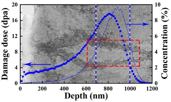
Figure 5.
Image showing the damage profile of tungsten implanted with He ions simulated with SRIM software superimposed on TEM image [102].
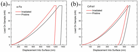
Figure 6.
Illustration of the influence of irradiation on instrumented indentation data. Load-displacement curves: (a) -Fe, (b) CrFeV alloy [103].
So far, there is no simple and reliable theory to link the indentation load-penetration curve to elastic and plastic properties of the material. Thus, since the nanoindentation test is generally performed on one grain of the polycrystalline material, the crystal plasticity finite element method can be successfully used to obtain the material properties from such a test [82,104,105,106,107,108,109]. In [110], the crystal plasticity model with Voce hardening was applied to simulate the indentation of pure Zr in virgin and irradiated states. The modified plastic properties of the irradiated material were simply obtained by changing the value of the initial CRSS of each slip system only, rather than by modification of the model itself. In [111], the strain-gradient crystal plasticity model was adopted to model the behaviour of ion-irradiated FCC single crystals. The irradiation effect was taken into account by adding the irradiation-induced defects term to the CRSS. The defect density was specified non-uniformly along the sample’s thickness.
In [112], the DDCP model similar to [67] was applied in order to study the irradiation effect on hardness of Chinese RPV A508-3 steel. A similar approach was applied to study indentation in the same material in [113]. A non-uniform distribution of defects aiming to reproduce the dpa profile across the thickness was accounted for. The authors used a conical indenter (instead of the Berkovich indenter applied in the experiment) and argued that such an approach is valid as the same projected area is obtained. However, if such an approach is really valid should be a matter of further studies.
The behaviour of self-ion irradiated tungsten was studied in [17] using nanoindentation, high-resolution EBSD, and small-strain strain-gradient crystal plasticity. To account for irradiation effects, the additional term was added to the CRSS. This term depended on the density of dislocation loops measured in TEM. Moreover, this term was decreasing with strain which accounted for weakening of defects by gliding dislocations—thus, a strain softening model was used. The CPFEM simulations of indentation in tungsten were also reported in [95]. The model includes irradiation hardening terms coming from voids and loops. However, only hardness values were compared against the experimental data, and no load-displacement curves were provided.
An interesting model able to capture both irradiation effects and pop-in behaviour in tungsten was published in [94]. The possibility to pop in was taken into account by introducing the probabilistic pop-in stress. The CRSS included terms related to DLs, He bubbles, statistically stored dislocations (SSDs), geometrically necessary dislocations (GNDs), and lattice friction. The model correctly predicted that irradiation leads to inhibiting pop-in possibilities.
While modelling the indentation of ion-implanted materials using CPFEM, one should be aware of several important effects. First, ideally the plastic zone should not exceed the flat part of dpa before the peak (see Figure 5). Since the plastic zone is 5–10 times larger than the indenter penetration, this results in severe restriction on the maximum penetration depth or necessitates usage of high ion energies (that lead to considerable ion penetration). Alternatively, one can consider variable defect density as it was performed in [111]. Performing nanoindentation at very small depths poses further challenges. First, at small depths, the size effect plays important role and one should use a size-sensitive model, e.g., [108,114,115,116]. Second, in the case of using pyramidal indenters, the influence of tip bluntness considerably affects the obtained mechanical response [117,118,119,120,121], thus necessitating to explicitly account for it. The simulated load-displacement curves using the Berkovich indenter blunted with three parabolic cylinders with different values of tip radius R (details of the CPFEM simulation will be published in another paper of the author soon) are shown in Figure 7. One can see that the influence of tip radius is considerable. As concerns friction, it seems that its effect on load-displacement curves can be neglected for small depths (see Figure 12 in [109]). On the other hand its effect on surface topography appears to be more severe.
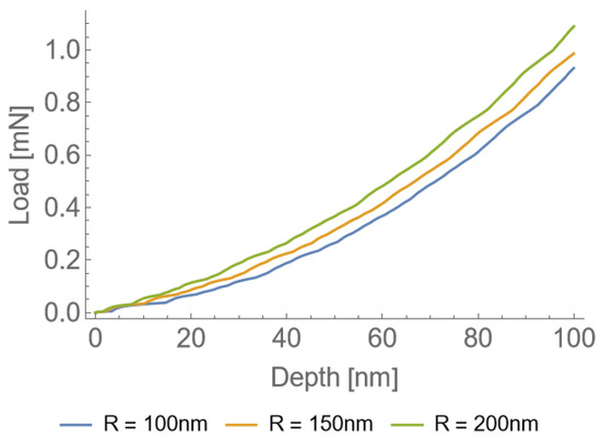
Figure 7.
Load-displacement curves obtained for different radii of the Berkovich tip.
5. Conclusions
The crystal plasticity theory is now well established in materials science. Direct consideration of irradiation effects started 15 years ago with the paper [56], where increase of the critical resolved shear stress due to the presence of irradiation-induced defect clusters was introduced. Since that time the CP theory has enabled to:
- Reproduce the experimentally observed irradiation hardening and post-yield softening;
- Develop analytical models of crack nucleation;
- Evaluate the influence of irradiation on DBTT, IGSCC as well as growth and coalescence of voids;
- Provide data for probabilistic assessment of brittle fracture.
However, when trying to apply the CP theory to model irradiated materials, one has to bear in mind some specific aspects. First, a different framework should be applied to each material. Obviously, lattice-specific and material-specific sets of deformation systems (slip, twin, transformation) have to be applied. Moreover, although the power-law-type flow equation seems to work correctly for FCC materials, this issue is more complicated for BCC and HCP materials. Despite the fact that the power law is inappropriate to cover entire strain rate and temperature ranges in such metals and alloys, it was demonstrated by some authors that it can still give reasonable predictions for narrower ranges. Finally, different defect types develop in different materials under irradiation, e.g., SFTs are common in copper, while DLs and SRCs are important in RPV steels. If one does not have the information about the most important defects, one should first perform TEM observations to determine the defect types and simulations with lower-scale models to find what are the interactions between a particular defect and gliding dislocations.
The CP theory is also of special importance when irradiation effects are studied using ion implantation and instrumented nanoindentation. First of all, as at this scale the indenter typically penetrates a single grain (rather than averaging response from a set of grains), one should account for the crystallographic orientation and CP modelling that is ideal for this. Moreover, contrary to lower-scale models, it enables to realistically reproduce experimental conditions. Second, it is technically possible to analyse even the case when distribution of irradiation defects is not uniform across the plastic zone. In such a case, one has to apply different defect densities at subsequent layers of elements.
Again, one has to be careful when trying to model the response of ion-implanted materials using the CP theory. First, the imperfection of the indenter’s tip plays an important role at low penetrations. One should thus reproduce the tip geometry as closely as possible, ideally by performing atomic force microscopy imaging of the tip. The second issue is the size effect believed to occur due to GNDs. If the size effect is present in the investigated case, one should apply some kind of strain-gradient CP model. Another issue is the presence of friction. Although friction does not considerably affect the load-displacement curves, it has a huge effect on surface topography.
Funding
We acknowledge support from the European Union Horizon 2020 research and innovation program under grant agreement no. 857470 and from the European Regional Development Fund via the Foundation for Polish Science International Research Agenda PLUS program grant No. MAB PLUS/2018/8.
Data Availability Statement
No new data were created or analyzed in this study.
Conflicts of Interest
The author declares no conflict of interest.
Abbreviations
The following abbreviations are used in this manuscript:
| NPP | nuclear power plant |
| PWR | pressurized water reactor |
| HCP | hexagonal close-packed |
| ASS | austenitic stainless steels |
| FCC | face-centred cubic |
| RPV | reactor pressure vessel |
| BCC | body-centred cubic |
| DBTT | ductile to brittle transition temperature |
| Gen-IV | generation IV |
| GIF | Generation-IV International Forum |
| VHTR | very high temperature gas-cooled reactor |
| GFR | gas-cooled fast reactor |
| SFR | sodium-cooled fast reactor |
| LFR | lead-cooled fast reactor |
| MSR | molten salt reactor |
| SCWR | super-critical water-cooled reactor |
| FM | ferritic–martensitic |
| ODS | oxide dispersion strengthened |
| PKA | primary knock-on atom |
| SFT | stacking fault tetrahedron |
| DL | dislocation loop |
| SRC | solute rich cluster |
| DBH | dispersed barrier hardening |
| dpa | displacement per atom |
| PCP | phenomenological crystal plasticity |
| DDCP | dislocation-density-based crystal plasticity |
| CRSS | critical resolved shear stress |
| RSS | resolved shear stress |
| IGSCC | intergranular stress corrosion cracking |
| IASCC | irradiation-assisted stress corrosion cracking |
| DC | dislocation channel |
| CPFEM | crystal plasticity finite element method |
| FFT | fast Fourier transform |
| EVPSC | elastic-viscoplastic self-consistent |
| BZ | Berveiller and Zaoui |
| SC | self-consistent |
| SSD | statistically stored dislocation |
| GND | geometrically necessary dislocation |
References
- Goldstein, J.; Qvist, S. A Bright Future: How Some Countries Have Solved Climate Change and the Rest Can Follow; PublicAffairs: New York, NY, USA, 2019. [Google Scholar]
- Fernández-Arias, P.; Vergara, D.; Orosa, J.A. A Global Review of PWR Nuclear Power Plants. Appl. Sci. 2020, 10, 4434. [Google Scholar] [CrossRef]
- El Shawish, S.; Vincent, P.G.; Moulinec, H.; Cizelj, L.; Gélébart, L. Full-field polycrystal plasticity simulations of neutron-irradiated austenitic stainless steel: A comparison between FE and FFT-based approaches. J. Nucl. Mater. 2020, 529, 151927. [Google Scholar] [CrossRef]
- Chakraborty, P.; Biner, S.B. Crystal plasticity modeling of irradiation effects on flow stress in pure-iron and iron-copper alloys. Mech. Mater. 2016, 101, 71–80. [Google Scholar] [CrossRef]
- Murty, K.L.; Charit, I. Structural materials for Gen-IV nuclear reactors: Challenges and opportunities. J. Nucl. Mater. 2008, 383, 189–195. [Google Scholar] [CrossRef]
- Abram, T.; Ion, S. Generation-IV nuclear power: A review of the state of the science. Energy Policy 2008, 36, 4323–4330. [Google Scholar] [CrossRef]
- Talarowska, A.; Lipka, M.; Wojtania, G. Preliminary computational and experimental design studies of the ISHTAR thermostatic rig for the high-temperature reactors materials irradiation. Nukleonika 2021, 66, 127–132. [Google Scholar] [CrossRef]
- Skrzypek, E.; Muszyński, D.; Skrzypek, M.; Darnowski, P.; Malesa, J.; Boettcher, A.; Dąbrowski, M.P. Pre-Conceptual Design of the Research High-Temperature Gas-Cooled Reactor TeResa for Non-Electrical Applications. Energies 2022, 15, 2084. [Google Scholar] [CrossRef]
- Čížek, J.; Kalivodová, J.; Janeček, M.; Stráskỳ, J.; Srba, O.; Macková, A. Advanced structural materials for gas-cooled fast reactors—A review. Metals 2021, 11, 76. [Google Scholar] [CrossRef]
- Keiser, D.D., Jr. Fuel cladding chemical interaction in metallic sodium fast reactor fuels: A historical perspective. J. Nucl. Mater. 2019, 514, 393–398. [Google Scholar] [CrossRef]
- Żurkowski, W.; Sawicki, P.; Kubiński, W.; Darnowski, P. Application of genetic algorithms in optimization of SFR nuclear reactor design. Nukleonika 2021, 66, 139–145. [Google Scholar] [CrossRef]
- Zaborowska, A.; Kurpaska, L.; Wyszkowska, E.; Clozel, M.; Vanazzi, M.; Di Fonzo, F.; Turek, M.; Jóźwik, I.; Kosińska, A.; Jagielski, J. Influence of ion irradiation on the nanomechanical properties of thin alumina coatings deposited on 316L SS by PLD. Surf. Coat. Technol. 2020, 386, 125491. [Google Scholar] [CrossRef]
- Wright, R.; Sham, T.L. Status of Metallic Structural Materials for Molten Salt Reactors; Technical Report; Idaho National Lab. (INL): Idaho Falls, ID, USA; Argonne National Lab. (ANL): Argonne, IL, USA, 2018. [Google Scholar]
- Guzonas, D.; Novotny, R. Supercritical water-cooled reactor materials—Summary of research and open issues. Prog. Nucl. Energy 2014, 77, 361–372. [Google Scholar] [CrossRef]
- Yvon, P.; Le Flem, M.; Cabet, C.; Seran, J.L. Structural materials for next generation nuclear systems: Challenges and the path forward. Nucl. Eng. Des. 2015, 294, 161–169. [Google Scholar] [CrossRef]
- Frelek-Kozak, M.; Kurpaska, L.; Mulewska, K.; Zieliński, M.; Diduszko, R.; Kosińska, A.; Kalita, D.; Chromiński, W.; Turek, M.; Kaszyca, K.; et al. Mechanical behavior of ion-irradiated ODS RAF steels strengthened with different types of refractory oxides. Appl. Surf. Sci. 2023, 610, 155465. [Google Scholar] [CrossRef]
- Das, S.; Yu, H.; Mizohata, K.; Tarleton, E.; Hofmann, F. Modified deformation behaviour of self-ion irradiated tungsten: A combined nano-indentation, HR-EBSD and crystal plasticity study. Int. J. Plast. 2020, 135, 102817. [Google Scholar] [CrossRef]
- El-Atwani, O.; Li, N.; Li, M.; Devaraj, A.; Baldwin, J.; Schneider, M.; Sobieraj, D.; Wróbel, J.; Nguyen-Manh, D.; Maloy, S.; et al. Outstanding radiation resistance of tungsten-based high-entropy alloys. Sci. Adv. 2019, 5, eaav2002. [Google Scholar] [CrossRef]
- Wang, Y.; Sun, X.; Zhao, J. A mechanism-based quantitative multi-scale framework for investigating irradiation hardening of tungsten at low temperature. Mater. Sci. Eng. A 2020, 774, 138941. [Google Scholar] [CrossRef]
- Domínguez-Gutiérrez, F.; Papanikolaou, S.; Esfandiarpour, A.; Sobkowicz, P.; Alava, M. Nanoindentation of single crystalline Mo: Atomistic defect nucleation and thermomechanical stability. Mater. Sci. Eng. A 2021, 826, 141912. [Google Scholar] [CrossRef]
- Garner, F.; Hamilton, M.; Panayotou, N.; Johnson, G. The microstructural origins of yield strength changes in AISI 316 during fission or fusion irradiation. J. Nucl. Mater. 1981, 104, 803–807. [Google Scholar] [CrossRef]
- Odette, G.; Lucas, G. Recent progress in understanding reactor pressure vessel steel embrittlement. Radiat. Eff. Defects Solids 1998, 144, 189–231. [Google Scholar] [CrossRef]
- Zinkle, S.; Maziasz, P.; Stoller, R. Dose dependence of the microstructural evolution in neutron-irradiated austenitic stainless steel. J. Nucl. Mater. 1993, 206, 266–286. [Google Scholar] [CrossRef]
- Zhang, H.; Long, B.; Dai, Y. Metallography studies and hardness measurements on ferritic/martensitic steels irradiated in STIP. J. Nucl. Mater. 2008, 377, 122–131. [Google Scholar] [CrossRef]
- English, C.; Hyde, J. Radiation Damage of Reactor Pressure Vessel Steels; Elsevier: Amsterdam, The Netherlands, 2012. [Google Scholar]
- Slugeň, V.; Sojak, S.; Egger, W.; Krsjak, V.; Simeg Veternikova, J.; Petriska, M. Radiation damage of reactor pressure vessel steels studied by positron annihilation spectroscopy—A Review. Metals 2020, 10, 1378. [Google Scholar] [CrossRef]
- Monnet, G. Multiscale modeling of irradiation hardening: Application to important nuclear materials. J. Nucl. Mater. 2018, 508, 609–627. [Google Scholar] [CrossRef]
- Krishna, S.; Zamiri, A.; De, S. Dislocation and defect density-based micromechanical modeling of the mechanical behavior of FCC metals under neutron irradiation. Philos. Mag. 2010, 90, 4013–4025. [Google Scholar] [CrossRef]
- Patra, A.; McDowell, D. Crystal plasticity-based constitutive modelling of irradiated BCC structures. Philos. Mag. 2012, 92, 861–887. [Google Scholar] [CrossRef]
- Patra, A.; Tomé, C.; Golubov, S. Crystal plasticity modeling of irradiation growth in Zircaloy-2. Philos. Mag. 2017, 97, 2018–2051. [Google Scholar] [CrossRef]
- Xiao, X.; Terentyev, D.; Yu, L.; Bakaev, A.; Jin, Z.; Duan, H. Investigation of the thermo-mechanical behavior of neutron-irradiated Fe-Cr alloys by self-consistent plasticity theory. J. Nucl. Mater. 2016, 477, 123–133. [Google Scholar] [CrossRef]
- Chakraborty, P.; Biner, S.; Zhang, Y.; Spencer, B. Crystal Plasticity Model of Reactor Pressure Vessel Embrittlement in Grizzly; Technical Report; Idaho National Lab (INL): Idaho Falls, ID, USA, 2015. [Google Scholar]
- Seeger, A. On the theory of radiation damage and radiation hardening. In Proceedings of the 2nd UN International Conference on Peaceful Uses of Atomic Energy, Geneva, Switzerland, 1–13 September 1958; Volume 6, p. 250. [Google Scholar]
- Roldán, M.; Sánchez, F.J.; Fernández, P.; Ortiz, C.J.; Gómez-Herrero, A.; Rey, D.J. Dislocation Loop Generation Differences between Thin Films and Bulk in EFDA Pure Iron under Self-Ion Irradiation at 20 MeV. Metals 2021, 11, 2000. [Google Scholar] [CrossRef]
- Patra, A.; McDowell, D. A void nucleation and growth based damage framework to model failure initiation ahead of a sharp notch in irradiated BCC materials. J. Mech. Phys. Solids 2015, 74, 111–135. [Google Scholar] [CrossRef]
- Weeks, J.; Czajkowski, C.; Tichler, P. Effects of high thermal and high fast fluences on the mechanical properties of type 6061 aluminum on the HFBR. In Proceedings of the Effects of Radiation on Materials: 14th International Symposium (Volume II), Andover, MA, USA, 27–29 June 1988; ASTM International: West Conshohocken, PA, USA, 1990. [Google Scholar]
- Faulkner, R. Radiation-induced grain boundary segregation in nuclear reactor steels. J. Nucl. Mater. 1997, 251, 269–275. [Google Scholar] [CrossRef]
- Vaidya, W.; Ehrlich, K. Radiation-induced recrystallization, its cause and consequences in heavy-ion irradiated 20% cold-drawn steels of type 1.4970. J. Nucl. Mater. 1983, 113, 149–162. [Google Scholar] [CrossRef]
- Griffiths, M. Effect of Neutron Irradiation on the Mechanical Properties, Swelling and Creep of Austenitic Stainless Steels. Materials 2021, 14, 2622. [Google Scholar] [CrossRef] [PubMed]
- Bergner, F.; Hernández-Mayoral, M.; Heintze, C.; Konstantinović, M.J.; Malerba, L.; Pareige, C. TEM Observation of Loops Decorating Dislocations and Resulting Source Hardening of Neutron-Irradiated Fe-Cr Alloys. Metals 2020, 10, 147. [Google Scholar] [CrossRef]
- Zhang, F.; Boatner, L.; Zhang, Y.; Chen, D.; Wang, Y.; Wang, L. Swelling and Helium Bubble Morphology in a Cryogenically Treated FeCrNi Alloy with Martensitic Transformation and Reversion after Helium Implantation. Materials 2019, 12, 2821. [Google Scholar] [CrossRef] [PubMed]
- Kinchin, G.H.; Pease, R.S. The displacement of atoms in solids by radiation. Rep. Prog. Phys. 1955, 18, 1. [Google Scholar] [CrossRef]
- Was, G.S. Fundamentals of Radiation Materials Science: Metals and Alloys; Springer: Cham, Swizterland, 2017. [Google Scholar]
- Ziegler, J.F.; Ziegler, M.; Biersack, J. SRIM— The stopping and range of ions in matter. Nucl. Instrum. Methods Phys. Res. Sect. B Beam Interact. Mater. Atoms 2010, 268, 1818–1823. [Google Scholar] [CrossRef]
- Crocombette, J.-P.; Van Wambeke, C. Quick calculation of damage for ion irradiation: Implementation in Iradina and comparisons to SRIM. EPJ Nucl. Sci. Technol. 2019, 5, 7. [Google Scholar] [CrossRef]
- Perzyna, P. Theory of viscoplasticity of irradiated materials. Arch. Mech. 1974, 26, 81–93. [Google Scholar]
- Arsenlis, A.; Wirth, B.; Rhee, M. Dislocation density-based constitutive model for the mechanical behaviour of irradiated Cu. Philos. Mag. 2004, 84, 3617–3635. [Google Scholar] [CrossRef]
- Skoczeń, B.; Ustrzycka, A. Kinetics of evolution of radiation induced micro-damage in ductile materials subjected to time-dependent stresses. Int. J. Plast. 2016, 80, 86–110. [Google Scholar] [CrossRef]
- Ryś, M.; Skoczeń, B. Coupled constitutive model of damage affected two-phase continuum. Mech. Mater. 2017, 115, 1–15. [Google Scholar] [CrossRef]
- Ustrzycka, A.; Skoczeń, B.; Nowak, M.; Kurpaska, Ł.; Wyszkowska, E.; Jagielski, J. Elastic–plastic-damage model of nano-indentation of the ion-irradiated 6061 aluminium alloy. Int. J. Damage Mech. 2020, 29, 1271–1305. [Google Scholar] [CrossRef]
- Nowak, M.; Mulewska, K.; Azarov, A.; Ustrzycka, A. A peridynamic elasto-plastic damage model for ion-irradiated materials. Int. J. Mech. Sci. 2023, 237, 107806. [Google Scholar] [CrossRef]
- Vincent, L.; Libert, M.; Marini, B.; Rey, C. Towards a modelling of RPV steel brittle fracture using crystal plasticity computations on polycrystalline aggregates. J. Nucl. Mater. 2010, 406, 91–96. [Google Scholar] [CrossRef]
- Singh, K.; Robertson, C.; Bhaduri, A. Brittle fracture model parameter estimation for irradiated BCC material through dislocation based crystal plasticity model. Frat. Ed Integrità Strutt. 2019, 13, 319–330. [Google Scholar] [CrossRef]
- Evrard, P.; Sauzay, M. Modelling of the effect of dislocation channel on intergranular microcrack nucleation in pre-irradiated austenitic stainless steels during low strain rate tensile loading. J. Nucl. Mater. 2010, 405, 83–94. [Google Scholar] [CrossRef]
- Ling, C.; Tanguy, B.; Besson, J.; Forest, S.; Latourte, F. Void growth and coalescence in triaxial stress fields in irradiated FCC single crystals. J. Nucl. Mater. 2017, 492, 157–170. [Google Scholar] [CrossRef]
- Deo, C.; Tomé, C.; Lebensohn, R.; Maloy, S. Modeling and simulation of irradiation hardening in structural ferritic steels for advanced nuclear reactors. J. Nucl. Mater. 2008, 377, 136–140. [Google Scholar] [CrossRef]
- Onimus, F.; Béchade, J.L. A polycrystalline modeling of the mechanical behavior of neutron irradiated zirconium alloys. J. Nucl. Mater. 2009, 384, 163–174. [Google Scholar] [CrossRef]
- Erinosho, T.; Dunne, F. Strain localization and failure in irradiated zircaloy with crystal plasticity. Int. J. Plast. 2015, 71, 170–194. [Google Scholar] [CrossRef]
- Onimus, F.; Gelebart, L.; Brenner, R. Polycrystalline simulations of in-reactor deformation of recrystallized Zircaloy-4 tubes: Fast Fourier Transform computations and mean-field self-consistent model. Int. J. Plast. 2022, 153, 103272. [Google Scholar] [CrossRef]
- Hardie, C.; Thomas, R.; Liu, Y.; Frankel, P.; Dunne, F. Simulation of crystal plasticity in irradiated metals: A case study on Zircaloy-4. Acta Mater. 2022, 241, 118361. [Google Scholar] [CrossRef]
- Jose, N.M.; Samal, M.; Durgaprasad, P.; Alankar, A.; Dutta, B. Crystal plasticity modelling of neutron irradiation effects on the flow and damage behaviour of Zircaloy-4. In Advances in Structural Integrity: Structural Integrity Over Multiple Length Scales; Springer: Cham, Swizterland, 2022; pp. 255–265. [Google Scholar]
- Xiao, X.; Song, D.; Xue, J.; Chu, H.; Duan, H. A size-dependent tensorial plasticity model for FCC single crystal with irradiation. Int. J. Plast. 2015, 65, 152–167. [Google Scholar] [CrossRef]
- Barton, N.; Arsenlis, A.; Marian, J. A polycrystal plasticity model of strain localization in irradiated iron. J. Mech. Phys. Solids 2013, 61, 341–351. [Google Scholar] [CrossRef]
- Xiao, X.; Song, D.; Xue, J.; Chu, H.; Duan, H. A self-consistent plasticity theory for modeling the thermo-mechanical properties of irradiated FCC metallic polycrystals. J. Mech. Phys. Solids 2015, 78, 1–16. [Google Scholar] [CrossRef]
- Sabar, H.; Berveiller, M.; Favier, V.; Berbenni, S. A new class of micro-micro models for elastic-viscoplastic heterogeneous materials. Int. J. Solids Struct. 2002, 39, 3257–3276. [Google Scholar] [CrossRef]
- Nie, J.; Liu, Y.; Lin, P.; Xie, Q.; Liu, Z. A crystal plasticity model with irradiation effect for the mechanical behavior of FCC metals. Acta Mech. Solida Sin. 2019, 32, 675–687. [Google Scholar] [CrossRef]
- Nie, J.; Liu, Y.; Xie, Q.; Liu, Z. Study on the irradiation effect of mechanical properties of RPV steels using crystal plasticity model. Nucl. Eng. Technol. 2019, 51, 501–509. [Google Scholar] [CrossRef]
- Liu, W.; Chen, L.; Yu, L.; Fu, J.; Duan, H. Continuum modeling of dislocation channels in irradiated metals based on stochastic crystal plasticity. Int. J. Plast. 2022, 151, 103211. [Google Scholar] [CrossRef]
- Han, X. Modeling of Cavity Swelling-Induced Embrittlement in Irradiated Austenitic Stainless Steels; Modelisation de la Fragilisation due au Gonflement dans les Aciers Inoxydables Austenitiques Irradies. Ph.D. Thesis, Ecole Nationale Superieure des Mines de Paris University, Paris, France, 2012. [Google Scholar]
- Tanguy, B.; Han, X.; Besson, J.; Forest, S.; Robertson, C.; Rupin, N. Dislocations and irradiation defects-based micromechanical modelling for neutron irradiated austenitic stainless steels. In Proceedings of the International Symposium on Plasticity, Barcelona, Spain, 3–5 September 2013; pp. 3–8. [Google Scholar]
- El Shawish, S.; Cizelj, L.; Tanguy, B.; Han, X.; Hure, J. Extended crystal plasticity finite element approach for neutron irradiated austenitic stainless steels. In Proceedings of the 23rd International Conference Nuclear Energy for New Europe, Portorož, Slovenia, 8–11 September 2014. [Google Scholar]
- El Shawish, S.; Cizelj, L.; Tanguy, B.; Han, X.; Hure, J. Macroscopic Validation of the Micromechanical Model for Neutron-Irradiated Stainless Steel. In Proceedings of the 25th International Conference Nuclear Energy for New Europe, Portorož, Slovenia, 5–8 September 2016. [Google Scholar]
- Hure, J.; El Shawish, S.; Cizelj, L.; Tanguy, B. Intergranular stress distributions in polycrystalline aggregates of irradiated stainless steel. J. Nucl. Mater. 2016, 476, 231–242. [Google Scholar] [CrossRef]
- Vincent, P.G.; Moulinec, H.; Joëssel, L.; Idiart, M.I.; Gărăjeu, M. Porous polycrystal plasticity modeling of neutron-irradiated austenitic stainless steels. J. Nucl. Mater. 2020, 542, 152463. [Google Scholar] [CrossRef]
- Liang, D.; Hure, J.; Courcelle, A.; El Shawish, S.; Tanguy, B. A micromechanical analysis of intergranular stress corrosion cracking of an irradiated austenitic stainless steel. Acta Mater. 2021, 204, 116482. [Google Scholar] [CrossRef]
- Monnet, G.; Mai, C. Prediction of irradiation hardening in austenitic stainless steels: Analytical and crystal plasticity studies. J. Nucl. Mater. 2019, 518, 316–325. [Google Scholar] [CrossRef]
- Berveiller, M.; Zaoui, A. An extension of the self-consistent scheme to the plastically flowing polycrystals. J. Mech. Phys. Solids 1978, 26, 325–344. [Google Scholar] [CrossRef]
- Asaro, R.J.; Needleman, A. Texture Development and Strain Hardening in Rate Dependent Polycrystals. Acta Metall. 1985, 33, 923–953. [Google Scholar] [CrossRef]
- Frydrych, K.; Kowalczyk-Gajewska, K. A three-scale crystal plasticity model accounting for grain refinement in FCC metals subjected to severe plastic deformations. Mater. Sci. Eng. A 2016, 658, 490–502. [Google Scholar] [CrossRef]
- Frydrych, K. Simulations of Grain Refinement in Various Steels Using the Three-Scale Crystal Plasticity Model. Metall. Mater. Trans. A 2019, 50, 4913–4919. [Google Scholar] [CrossRef]
- Girard, G.; Frydrych, K.; Kowalczyk-Gajewska, K.; Martiny, M.; Mercier, S. Cyclic response of electrodeposited copper films. Experiments versus elastic-viscoplastic mean-field approach predictions. Mech. Mater. 2021, 153, 103685. [Google Scholar] [CrossRef]
- Frydrych, K.; Dominguez, J.; Alava, M.; Papanikolaou, S. Multiscale nanoindentation modeling of concentrated solid solutions: A continuum plasticity model. Mech. Mater. 2023, 181, 104644. [Google Scholar] [CrossRef]
- Kothari, M.; Anand, L. Elasto-viscoplastic constitutive equations for polycrystalline metals: Application to tantalum. J. Mech. Phys. Solids 1998, 46, 51–83. [Google Scholar] [CrossRef]
- Kocks, U.F.; Argon, A.S.; Ashby, M.F. Thermodynamics and kinetics of slip. Prog. Mater. Sci. 1975, 19, 304. [Google Scholar]
- Orowan, E. Problems of plastic gliding. Proc. Phys. Soc. 1940, 52, 8. [Google Scholar] [CrossRef]
- Patra, A.; McDowell, D. Continuum modeling of localized deformation in irradiated BCC materials. J. Nucl. Mater. 2013, 432, 414–427. [Google Scholar] [CrossRef]
- Xiao, X.; Terentyev, D.; Yu, L.; Song, D.; Bakaev, A.; Duan, H. Modelling irradiation-induced softening in BCC iron by crystal plasticity approach. J. Nucl. Mater. 2015, 466, 312–315. [Google Scholar] [CrossRef]
- Song, D.; Xiao, X.; Xue, J.; Chu, H.; Duan, H. Mechanical properties of irradiated multi-phase polycrystalline BCC materials. Acta Mech. Sin. 2015, 31, 191–204. [Google Scholar] [CrossRef]
- Monnet, G.; Vincent, L.; Gélébart, L. Multiscale modeling of crystal plasticity in Reactor Pressure Vessel steels: Prediction of irradiation hardening. J. Nucl. Mater. 2019, 514, 128–138. [Google Scholar] [CrossRef]
- Patra, A.; McDowell, D. Crystal plasticity investigation of the microstructural factors influencing dislocation channeling in a model irradiated BCC material. Acta Mater. 2016, 110, 364–376. [Google Scholar] [CrossRef]
- Krishna, S.; De, S. A temperature and rate-dependent micromechanical model of molybdenum under neutron irradiation. Mech. Mater. 2011, 43, 99–110. [Google Scholar] [CrossRef]
- Wang, Y.; Sun, X.; Zhao, J. Examining deformation localization of irradiated tungsten under uniaxial compression with crystal plasticity. Int. J. Refract. Met. Hard Mater. 2021, 100, 105637. [Google Scholar] [CrossRef]
- Yu, Q.; Chatterjee, S.; Roche, K.J.; Po, G.; Marian, J. Coupling crystal plasticity and stochastic cluster dynamics models of irradiation damage in tungsten. Model. Simul. Mater. Sci. Eng. 2021, 29, 055021. [Google Scholar] [CrossRef]
- Xiao, X.; Li, S.; Yu, L. Effect of irradiation damage and indenter radius on pop-in and indentation stress-strain relations: Crystal plasticity finite element simulation. Int. J. Mech. Sci. 2021, 199, 106430. [Google Scholar] [CrossRef]
- Shi, J.; Liu, G.; Wu, K.; Yu, P.; Zhu, H.; Zhao, G.; Shen, Y. Experiments and/or crystal plasticity finite element modeling of the mechanical properties of pristine and irradiated tungsten single crystal. Int. J. Plast. 2022, 154, 103293. [Google Scholar] [CrossRef]
- Lebensohn, R.A.; Tomé, C.N. A self-consistent anisotropic approach for the simulation of plastic deformation and texture development of polycrystals: Application to zirconium alloys. Acta Metall. Mater. 1993, 41, 2611–2624. [Google Scholar] [CrossRef]
- Hosemann, P.; Vieh, C.; Greco, R.; Kabra, S.; Valdez, J.; Cappiello, M.; Maloy, S. Nanoindentation on ion irradiated steels. J. Nucl. Mater. 2009, 389, 239–247. [Google Scholar] [CrossRef]
- Hosemann, P.; Kiener, D.; Wang, Y.; Maloy, S.A. Issues to consider using nano indentation on shallow ion beam irradiated materials. J. Nucl. Mater. 2012, 425, 136–139. [Google Scholar] [CrossRef]
- Kucharski, S.; Jarząbek, D. Depth dependence of nanoindentation pile-up patterns in copper single crystals. Metall. Mater. Trans. A 2014, 45, 4997–5008. [Google Scholar] [CrossRef]
- Clozel, M.; Kurpaska, L.; Jóźwik, I.; Jagielski, J.; Turek, M.; Diduszko, R.; Wyszkowska, E. Nanomechanical properties of low-energy Fe-ion implanted Eurofer97 and pure Fe. Surf. Coat. Technol. 2020, 393, 125833. [Google Scholar] [CrossRef]
- Mulewska, K.; Rovaris, F.; Dominguez-Gutierrez, F.; Huo, W.; Kalita, D.; Jozwik, I.; Papanikolaou, S.; Alava, M.; Kurpaska, L.; Jagielski, J. Self-ion irradiation effects on nanoindentation-induced plasticity of crystalline iron: A joint experimental and computational study. Nucl. Instrum. Methods Phys. Res. Sect. B Beam Interact. Mater. Atoms 2023, 539, 55–61. [Google Scholar] [CrossRef]
- Huang, W.; Sun, M.; Wen, W.; Yang, J.; Xie, Z.; Liu, R.; Wang, X.; Wu, X.; Fang, Q.; Liu, C. Strain Profile in the Subsurface of He-Ion-Irradiated Tungsten Accessed by S-GIXRD. Crystals 2022, 12, 691. [Google Scholar] [CrossRef]
- Su, Y.; Xia, S.; Huang, J.; Liu, Q.; Liu, H.; Wang, C.; Wang, Y. Irradiation Behaviors in BCC Multi-Component Alloys with Different Lattice Distortions. Metals 2021, 11, 706. [Google Scholar] [CrossRef]
- Kucharski, S.; Stupkiewicz, S.; Petryk, H. Surface Pile-Up Patterns in Indentation Testing of Cu Single Crystals. Exper. Mech. 2014, 54, 957–969. [Google Scholar] [CrossRef]
- Petryk, H.; Stupkiewicz, S.; Kucharski, S. On direct estimation of hardening exponent in crystal plasticity from the spherical indentation test. Int. J. Solids Struct. 2017, 112, 209–221. [Google Scholar] [CrossRef]
- Chakraborty, A.; Eisenlohr, P. Evaluation of an inverse methodology for estimating constitutive parameters in face-centered cubic materials from single crystal indentations. Eur. J. Mech. A/Solids 2017, 66, 114–124. [Google Scholar] [CrossRef]
- Frydrych, K. Crystal plasticity finite element simulations of the indentation test. Comput. Methods Mater. Sci. 2019, 19, 41–49. [Google Scholar] [CrossRef]
- Ryś, M.; Stupkiewicz, S.; Petryk, H. Micropolar regularization of crystal plasticity with the gradient-enhanced incremental hardening law. Int. J. Plast. 2022, 156, 103355. [Google Scholar] [CrossRef]
- Frydrych, K.; Papanikolaou, S. Unambiguous Identification of Crystal Plasticity Parameters from Spherical Indentation. Crystals 2022, 12, 1341. [Google Scholar] [CrossRef]
- Wang, Q.; Cochrane, C.; Skippon, T.; Wang, Z.; Abdolvand, H.; Daymond, M.R. Orientation-dependent irradiation hardening in pure Zr studied by nanoindentation, electron microscopies, and crystal plasticity finite element modeling. Int. J. Plast. 2019, 124, 133–154. [Google Scholar] [CrossRef]
- Xiao, X.; Chen, L.; Yu, L.; Duan, H. Modelling nano-indentation of ion-irradiated FCC single crystals by strain-gradient crystal plasticity theory. Int. J. Plast. 2019, 116, 216–231. [Google Scholar] [CrossRef]
- Nie, J.; Lin, P.; Liu, Y.; Zhang, H.; Wang, X. Simulation of the irradiation effect on hardness of Chinese HTGR A508-3 steels with CPFEM. Nucl. Eng. Technol. 2019, 51, 1970–1977. [Google Scholar] [CrossRef]
- Lin, P.; Nie, J.; Liu, M. Nanoindentation experiment and crystal plasticity study on the mechanical behavior of Fe-ion-irradiated A508-3 steel. J. Nucl. Mater. 2022, 571, 154002. [Google Scholar] [CrossRef]
- Petryk, H.; Stupkiewicz, S. A minimal gradient-enhancement of the classical continuum theory of crystal plasticity. Part I: The hardening law. Arch. Mech. 2016, 68, 459–485. [Google Scholar]
- Stupkiewicz, S.; Petryk, H. A minimal gradient-enhancement of the classical continuum theory of crystal plasticity. Part II: Size effects. Arch. Mech. 2016, 68, 487–513. [Google Scholar]
- Lewandowski, M.; Stupkiewicz, S. Size effects in wedge indentation predicted by a gradient-enhanced crystal-plasticity model. Int. J. Plast. 2018, 109, 54–78. [Google Scholar] [CrossRef]
- Torres-Torres, D.; Muñoz-Saldaña, J.; Gutierrez-Ladron-de Guevara, L.; Hurtado-Macías, A.; Swain, M. Geometry and bluntness tip effects on elastic–plastic behaviour during nanoindentation of fused silica: Experimental and FE simulation. Model. Simul. Mater. Sci. Eng. 2010, 18, 075006. [Google Scholar] [CrossRef]
- Krier, J.; Breuils, J.; Jacomine, L.; Pelletier, H. Introduction of the real tip defect of Berkovich indenter to reproduce with FEM nanoindentation test at shallow penetration depth. J. Mater. Res. 2012, 27, 28–38. [Google Scholar] [CrossRef]
- Čech, J.; Haušild, P.; Kovářík, O.; Materna, A. Examination of Berkovich indenter tip bluntness. Mater. Des. 2016, 109, 347–353. [Google Scholar] [CrossRef]
- Kovář, J.; Fuis, V.; Tomáštík, J. Influencing the indentation curves by the bluntness of the Berkovich indenter at the FEM modelling. In Proceedings of the 14th International Conference on Local Mechanical Properties—LMP 2019, Prague, Czech Republic, 11 June 2020; Volume 27, pp. 131–135. [Google Scholar]
- Sanchez-Camargo, C.M.; Hor, A.; Mabru, C. A robust inverse analysis method for elastoplastic behavior identification using the true geometry modeling of Berkovich indenter. Int. J. Mech. Sci. 2020, 171, 105370. [Google Scholar] [CrossRef]


Disclaimer/Publisher’s Note: The statements, opinions and data contained in all publications are solely those of the individual author(s) and contributor(s) and not of MDPI and/or the editor(s). MDPI and/or the editor(s) disclaim responsibility for any injury to people or property resulting from any ideas, methods, instructions or products referred to in the content. |
© 2023 by the author. Licensee MDPI, Basel, Switzerland. This article is an open access article distributed under the terms and conditions of the Creative Commons Attribution (CC BY) license (https://creativecommons.org/licenses/by/4.0/).