Article

Broadband Reflective Liquid Crystal Films Prepared by Rapid Inkjet Printing and Superposition Polymerization

1
Department of Materials Physics and Chemistry, School of Materials Science and Engineering, University of Science and Technology Beijing, Beijing 100083, China
2
Department of Chemistry and Chemical Engineering, School of Chemistry and Biological Engineering, University of Science and Technology Beijing, Beijing 100083, China
*
Author to whom correspondence should be addressed.
These authors contributed equally to this work.
Crystals 2022, 12(4), 473; https://doi.org/10.3390/cryst12040473
Submission received: 24 December 2021 / Revised: 25 March 2022 / Accepted: 27 March 2022 / Published: 29 March 2022
(This article belongs to the Special Issue 3D Printing/Additive Manufacturing of Alloys, Ceramics and Polymers)

Abstract

:
Inkjet printing is a non-contact, material saving and on-demand material manufacturing technology, which is able to be applied to the fabrication of functional materials with high efficiency. A new method for preparing broadband reflective cholesteric films based on inkjet printing and non-stick technology was proposed in this paper. The feasibility of automatic mixing of liquid crystal and doped materials in inkjet printing was studied. The spectral data of samples prepared by manual mixing and automatic mixing by inkjet printing were compared. It was found that the spectral error of the printed film was only less than 0.17 wt%, which reached or even exceeded the effect of manual mixing. The feasibility of preparing liquid crystal films with broadband reflection characteristics by stacking polymerization based on in situ UV polymerization and non-stick technology was verified. By changing the printing amount of chiral doped ink, the bandwidth of PSCLC film can be accurately controlled. This technology is expected to play an important role in scientific research and practical application.

1. Introduction

A polymer stabilized liquid crystal (PSLC) is composed of a small amount of polymer networks, which can stabilize the liquid crystal phase. Devices with PSLC have broad application prospects in information display, dimming film, and other fields.Cholesteric liquid crystals (Ch-LCs) are well-known as a type of LC material with a self-assembled helical superstructure [1,2,3,4].
In general, Ch-LCs is fabricated by adding chiral dopants as chirality inducing guests into an achiral nematic LC host. Broadband reflection is usually achieved by adjusting the pitch of Ch-LCs. Generally, traditional methods rely on artificial mixing to prepare broadband reflective cholesteric films. The time for preparation is long and the process is tedious. In particular, it is difficult to accurately weigh the chiral dopants manually, due to the fact that the proportion of chiral dopants in the whole mixture is very small and the center reflective wavelength is very sensitive to the proportion of chiral dopants [5,6,7]. Due to the influence of instrument errors and environmental changes, the selective reflection spectra of broadband reflective cholesteric films prepared in different batches are difficult to keep completely consistent. Therefore, a rapid batch fabrication technology of liquid crystal film is urgently needed.
The attractive features of inkjet printing technology include less material wastage, good film-forming effect, and scalability to large area manufacturing, which makes it a potential high-throughput parallel synthesis technology. For example, the mixed/composite materials of OLEDs dissolved in a binary solvent is directly deposited on the substrate by high-precision nozzle in inkjet printing. Thus, an organic light-emitting layer is formed, which is expected to replace the complex and expensive evaporation process in some fields. Inkjet printing of a thin-film library of donor/acceptor systems for potential applications in bulk heterojunction solar cells has been proved to be effective [8,9,10]. Applications that have used inkjet printing technology include printed flexible electronic devices, chemical sensors, biopharmaceutical, and many more [11,12,13]. As of now, there are only a few reports on inkjet-printed liquid crystal films libraries due to poor control over the accurate droplet manipulation and liquid-membrane transformation [14,15,16]. In addition, the orientation of liquid crystal is also a neglected factor [17,18].
In this paper, we successfully proposed a method of inkjet printing assisted preparation of broadband reflective liquid crystal films. Based on this method, cholesteric liquid crystal film precursors can be quickly prepared and optimized, and then combined with in situ UV polymerization and non-stick technology to form various optical polymer cholesteric liquid crystal films according to what is needed. In addition, by using the inkjet printing method, the preparation of liquid crystal films does not need an optical mask, can simply and quickly prepare liquid crystal films with various complex patterns or large areas, and can accurately and quickly optimize the preparation of liquid crystal films with less raw materials and less waste, playing a role in scientific research and practical application.

2. Experiments Methods
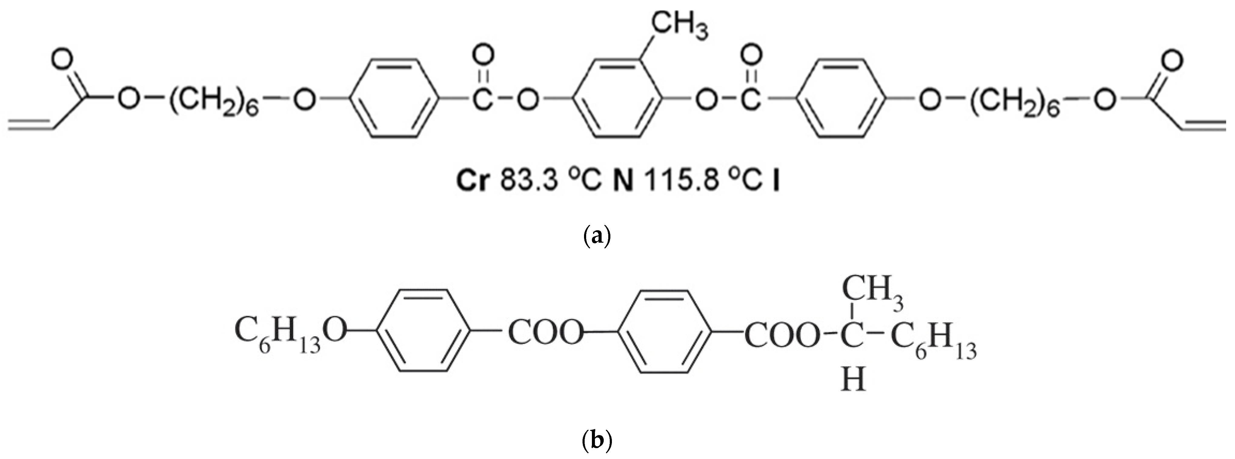
2.1. Materials

In this study, several common materials that can be completely dissolved in organic solvent (cyclohexanone) were commercially available and used without further purification, that is, nematic LC matrix (SLC-1717, no =  1.519, ne  =  1.720, Δn  =  ne − no  =  0.201, TN-I  =  92 °C, Shijiazhuang Yongsheng Huatsing Liquid Crystal Co., Ltd., Shijiazhuang, China), 1, 4-di-[4-(6-acryloyloxy) hexyloxy benzoyloxy]-2-methyl benzene (C6M, Beijing Kexin Jingyuan Science and Trade Co., Ltd., Beijing, China) as the monomer, (S)-2-octyl 4-[4-(hexyloxy)benzoyloxy]benzoate (S811, Beijing Bayi Space LCD Technology Co., Ltd., Beijing, China) as the chiral dopant, and 2,2-dimethopxy-1,2-diphenyl-ethanone (IRG651, TCI Co., Ltd., Beijing, China) as the photo-initiator, as shown in Figure 1. In addition, polytetrafluoroethylene preparation (PTFE, Dongguan Fuwang New Material Co., Ltd., Dongguan, China) was selected as the surface treatment agent.

2.2. Measurements

Crossed polarizing optical microscope (Olympus BX51) was used to observe and confirm the planar textures of cholesteric liquid crystals, which of each sample were taken by the onboard camera driven by Linksys software (version 2.43). The spectral properties of Ch-LC films were measured by UV/Vis/NIR spectrophotometry (JASCO V-570). Due to the spectral absorption of each film being almost negligible and that the light-scattering of the films did not change the position of the reflection wavelength, the transmittance results thus can reflect the reflection wavelength and bandwidth of the films. The contact angle of the substrate was mainly used to analyze the appropriate substrate for inkjet printing and was measured on the contact angle system OCA15 (Data Physics, Stuttgart, Germany).

2.3. Experimental Methods

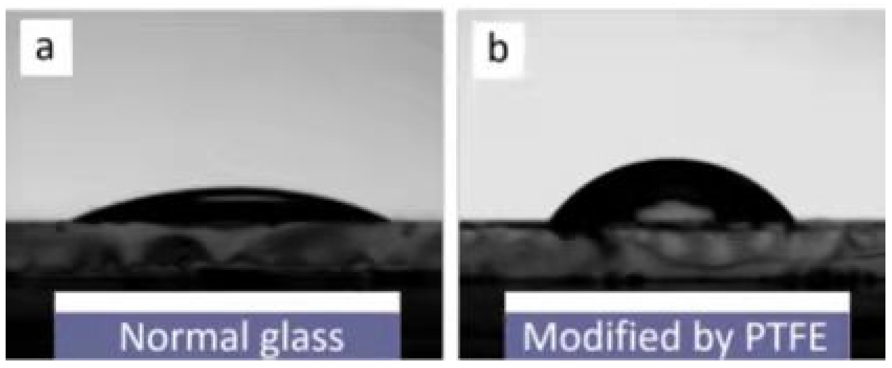
2.3.1. Substrate Preparation

The glass substrates were modified with oleophobic coatings (PTFE), and, as detailed in the following treatment: glass substrates were cut into 25 × 30 mm2 size, PTFE coating and ethanol were mixed in mass ratio of 1:1, and then stirred evenly for standby. The glass substrates were placed on the table homogenizer, and then spin coated with polytetrafluoroethylene ethanol solution. The substrate modified by PTFE was obtained by baking at 180 °C for 30 min.

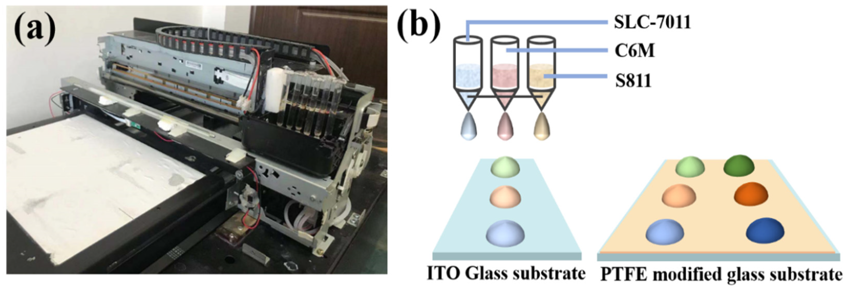
2.3.2. Ink Preparation

The PSCLC films in this experiment were mainly composed of liquid crystal, chiral dopants, polymerizable monomers, etc. Therefore, solvent ink was used to dissolve these organic compounds. The organic solvents in the ink usually include single solvents or their mixtures such as ethanol, cyclohexanone, cyclohexane, toluene, etc. The disadvantage of these inks was that the solvent volatilizes quickly in the nozzle, which easily leads to nozzle blockage. Cyclohexanone was chosen as the solvent of various organic compounds in this experiment because of its lower volatility and faster formation of the desirable liquid-crystalline phases following solvent removal. The three kinds of inks were prepared, respectively, and the specific preparation process was as follows: For “SLC-1717 with IRG 651 ink”: SLC-1717 (1.4 g) and IRG 651 (0.02 g) were dissolved in cyclohexanone (1.42 g). The solute concentration was 50 wt%. For “S811 ink”: S811 (0.2 g) was dissolved in cyclohexanone (1.8 g). The solute concentration was 10 wt%. For “C6M ink”: C6M (0.16 g) was dissolved in cyclohexanone (1.84 g). The solute concentration was 8 wt%.

2.3.3. Composition Variations Design

After the proportion of the target sample was designed, the CMY parameters of the target sample were searched in “the ink standard curve” database corresponding to the sample by the software developed by our lab. The “standard curves” of SLC-1717, S811, and C6M inks were shown in Section 3. Here, S811, C6M, and SLC-1717 ink correspond to the channels of C, M, and Y respectively. Then, composition variation designs of each sample were drafted in a color image with the corresponding CMY (cyan, magenta, and yellow) parameters by the computer design program (e.g., CorelDraw). In this experiment, the color images were designed as a circle with a diameter of 18 mm. Such sample points can be printed on the glass substrate with the size of 25 × 30 mm2, which was convenient for subsequent processing and detection.

2.3.4. Preparation of PSCLC Films by Ink Jet Printing

Prior to printing any ink, the IJP parameters had to be established. A piezoelectric drop-on-demand (DOD) inkjet printer (Dongsheng, Ltd., Beijing, China) was used in IJP. Its print head contains six color separate ink channels, and the inkjet volume of the four channels can be controlled independently by software (Acro-rip) and linked with CMYK of the images. The volume of the ink droplet can be precisely controlled, which was suitable for multiple-component liquid crystal film processing. The ink cartridge of the printer has been modified. The modified printer has a 2 mL transparent glass cartridge, and the ink will not stick to the inner wall of the glass cartridge, as shown in Figure 2. The consumption of ink was greatly reduced, and it was conducive to observe the amount of ink, so as to add ink in time. S811, C6M, and SLC-1717 inks were, respectively, filled into the channels of C, M, and Y, and the sample points were printed to the substrate controlled by software. Among them, the first layer of liquid crystal sample was printed on the ordinary glass substrate, and the samples of the second layer and above were printed on the substrate modified by PTFE. Then, the samples were transferred into a 40 °C oven for 2 h to remove the solvent.
The polyimide film spacer (5 μm thick) was placed on both sides of the dried sample to control the thickness of the liquid crystal film. The upper substrate with surface treatment was put on the samples since liquid crystals were oriented by extrusion. Then, the samples were processed by irradiating with UV light (1 mW/cm2, 365 nm) for 10 min at 25 °C, which results in the polymer networks of C6M, and the oleophobic upper substrate was slowly separated from the PSCLC layer. The film spacer was placed on both sides of the PSCLC film again, and the overall thickness of the spacer was controlled at 10 μm. The second liquid crystal sample was transferred from oleophobic substrate to the first layer of PSCLC film using the “sandwiching” method. Note that due to the sufficient bonding force between the liquid crystal and the substrate, the liquid crystal would not separate during the transfer process. Similar methods had been used in the fabrication of high-density microdroplet arrays. [19] Then, the samples were processed by irradiating with UV light (1 mW/cm2, 365 nm) for 10 min at 25 °C again, which resulted in a cell containing the sample of two layers PSCLC films. Finally, the same method was used to stack the third, fourth, and even more layers, and the thickness of each layer of PSCLC film was controlled by adding polyimide film.

2.3.5. Verified Experiment

In order to verify the accuracy of the component of the printed samples, several groups of monolayer ChLC films with different S811 contents were prepared by manual preparation. The subject systems were prepared by adding chiral dopants and LC monomer into nematic LC. To prepare the ChLCs films, the mixtures were injected into a glass cell by capillary action. The polyimide film spacer (5 μm thick) was used as cell spacers.

3. Results and Discussion

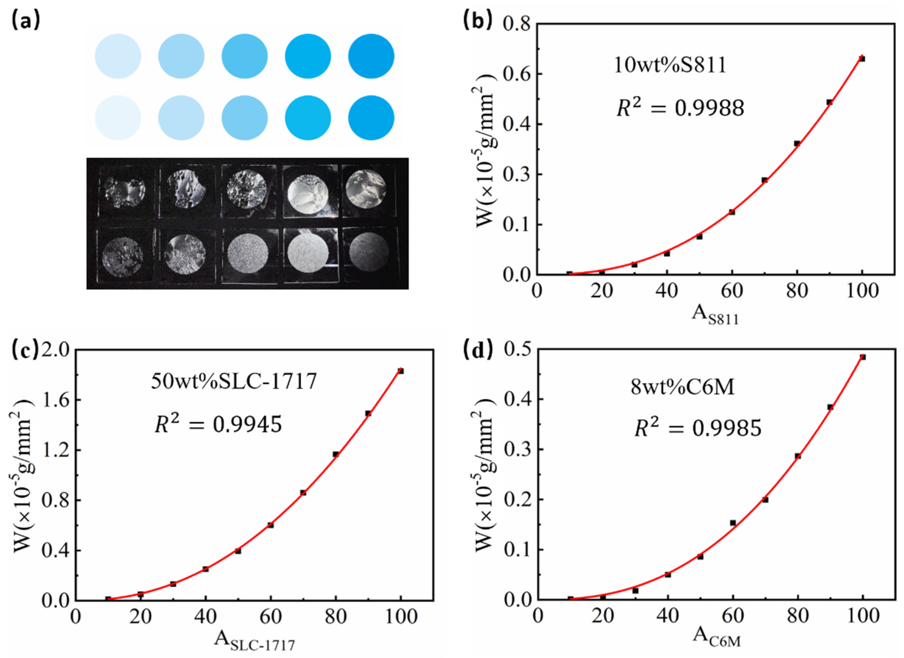
3.1. Establishment of a “Standard Curve”

In inkjet printing, each component in the liquid crystal film needs to be prepared into the ink required by the printer. In order to enable the computer to control the accurate printing of ink, it can be solved by establishing the standard printing curve of different ink. As we know, CMYK is one of the basic modes of color printing, and the chromaticity value of each channel is between 0 and 100. Taking S811 ink in cyan channel as an example, cyan circular patterns with different chromaticity values between 0 and 100 with intervals of 10 (colorimetric value (Ai): 10, 20, 30, …100) were made by using drawing software (such as CorelDraw) as shown in Figure 3a.
The weight of glass substrate before printing, after printing, and after drying should be accurately recorded in a precision balance, and then fitted to establish the relationship between printing volume and printing weight. As a result, a good curve of the printed weigh to the value range between 0 and 100 was obtained in Figure 3b–d. The correlation coefficients between variables were 0.9988, 0.9945, and 0.9985, respectively. The good nonlinear dependence relation demonstrates that the method of IJP were accurate and feasible in preparing Ch-LC films.
After the above printing and weighing steps, the “standard curve” function can be thus fitted according to the relationship between the chromaticity value and the deposition weight (after drying) in different circular patterns. Then, 100 integer chromaticity values and the corresponding mass per unit area can be read out from the curve, so as to build the database for accurate printing in the next step. For example, to search for a three-component sample, the print proportion will be searched from 100 × 100 × 100 sample banks, which were large enough to meet our needs. This process can be searched through a programmed program, and then the printing patterns required for the actual proportion can be made based on these databases, so as to realize the automatic mixing of samples by inkjet printing.

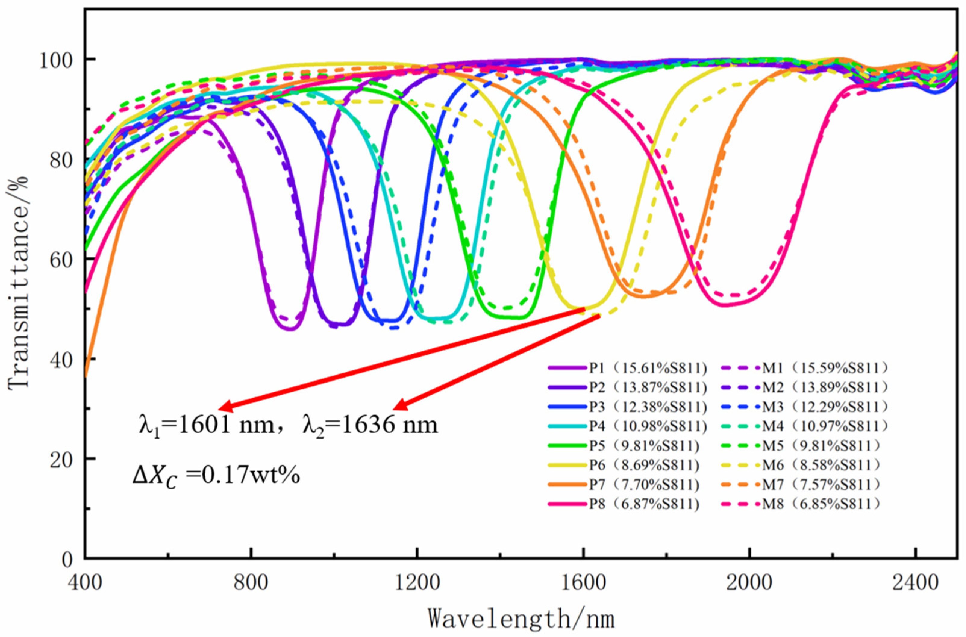
3.2. Accuracy of Inkjet Printing

In order to verify the accuracy of the composition of multi-channel inkjet printed PSCLC films, eight groups of single-layer PSCLC films with the same target component were prepared by hand and printing, respectively. The selective reflection spectrum of the two kinds of samples was measured by UV/Vis/NIR spectrophotometry, as shown in Figure 4. According to the difference of the center reflective wavelength of each group of samples, the maximum printing error concentration can be obtained reversibly. The preparation process of Ch-LC films by inkjet printing and manual printing was presented in Section 2. The printing samples and manual mixing samples components in this study were mentioned in Table 1 and Table 2. It was necessary to note that the content of liquid crystalline polymerizable monomer C6M and photoinitiator IRG651 were controlled to 15 wt% and 1 wt% in our expectation, However, there was an error of less than 0.15 wt% between the printing proportion and the target proportion found in the standard curve library, so the manual proportion was adjusted to keep the proportion as consistent as possible.
Figure 4 shows the comparison of transmission spectra between inkjet printing and hand-made Ch-LC films. It can be seen from the graph that the center reflective wavelength of the samples prepared by different methods was very close. Among all the samples, the P6 and M6 samples had the largest difference in the reflection wavelength, and their reflection wavelength were 1601 nm and 1636 nm, respectively. The concentration differences of the chiral dopants can be calculated according to Equations (1)–(3):
λ = n × P ,
P = 1 HTP × X C ,
Δ X C = n HTP × ( 1 λ 1 1 λ 2 ) .
Here, P was the pitch of Ch-LC, Xc was the weight concentration of chiral dopant, λ was the center reflective wavelength, and n was the average birefringence of the LC. It was known that the HTP value of S811 was about 13 μm−1, and the average birefringence of SLC-1717 was 1.62. So, the concentration difference of chiral dopants in P6 and M6 samples was 0.17 wt%. Due to the inaccuracy of manual mixing, P6 and M6 had a concentration difference of S811, which was 0.11 wt%. In addition, the HTP value of S811, the average refractive index of mixed system and weighing error, can be classified as a systematic error. The minimal concentration error demonstrates that it was feasible to control the composition of Ch-LC films by inkjet printing.

3.3. Principle of Unsticking Technology

The upper substrate needs to be peeled off several times in the process of preparing PSCLC film by multilayer stack printing liquid crystal film. In order to realize the smooth stripping of the upper substrate without destroying the plane texture of the PSCLC film, the surface modification of the upper substrate was required. PTFE was a kind of self-lubricating polymer material and its structure formula was -[-CF2-CF2-]-n-. Because of the strong electronegativity of fluorine ion, the molecules have small polarity and intermolecular force, and the material surface has low surface energy [20]. Therefore, the binding force of glass substrate modified by PTFE to liquid crystal will be less than that of ordinary glass substrate.
The contact angle test results of ordinary glass substrate and PTFE modified glass substrate were shown in Figure 5. Cetane was used as the standard reagent in the test. The contact angle of ordinary glass substrate was 23.0 ± 0.5° and that of glass substrate modified by PTFE was 56.3 ± 0.5°, as shown in Figure 5b. The oil affinity and hydrophobicity of the two kinds of substrates were quite different, which ensures the difference of adhesion between the upper and lower substrates to PSCLC films.

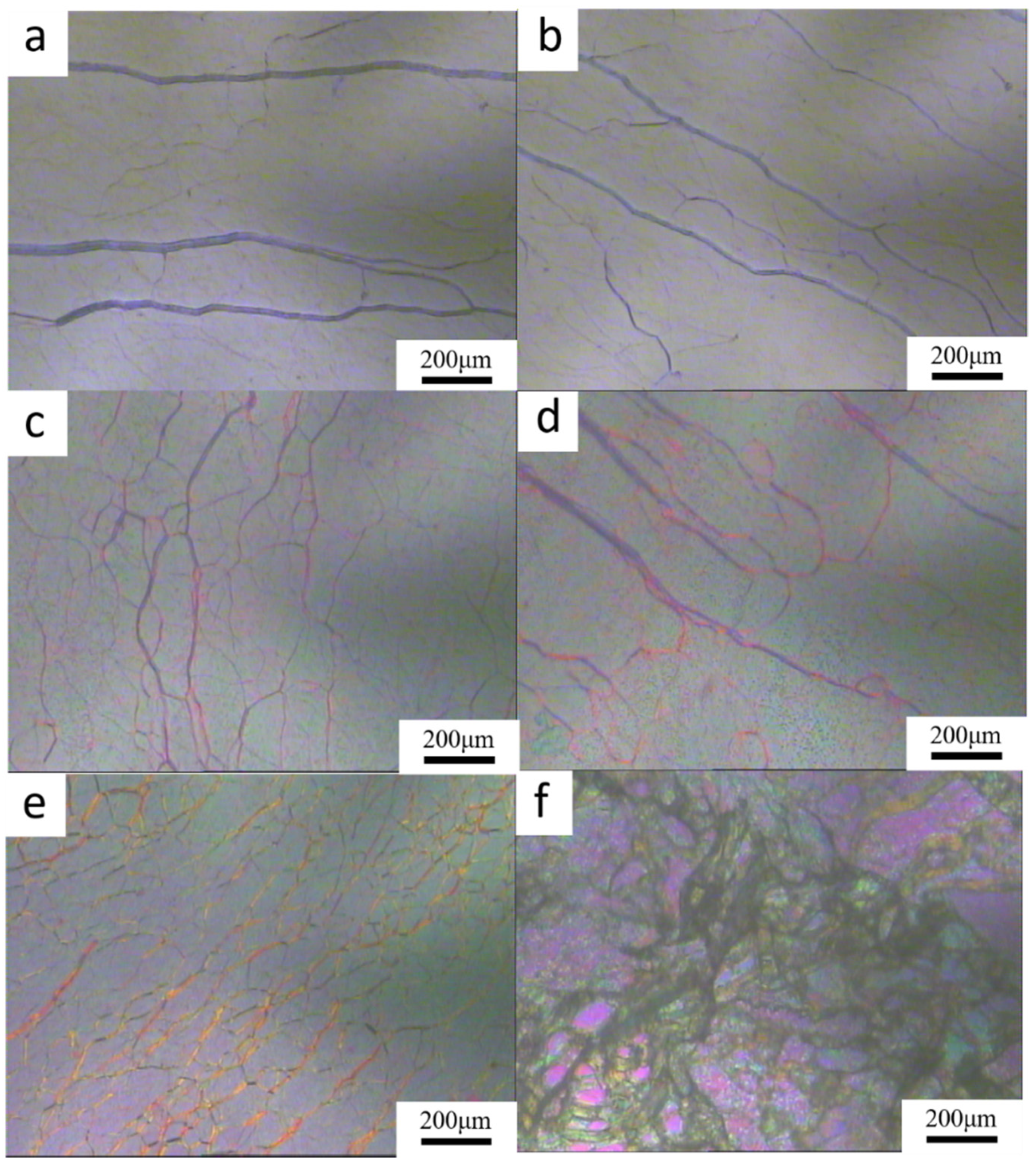
3.4. Morphology of the PSCLC Layer on the Substrate

The difference of adhesion between the upper and lower substrates ensures that the planar texture of PSCLC film can be retained completely after the PTFE modified glass substrate was removed. In order to understand the effect of the morphology of each layer of PSCLC after removing the upper substrate, structural information was obtained by POM (Figure 6). Figure 6a shows the PSCLC film formed by pressure orientation and UV polymerization of the sample prepared by inkjet printing, while Figure 6b shows the texture of PSCLC after peeling PTFE modified glass substrate. Comparing Figure 6a,b, the plane texture of the PSCLC film was clear and complete after peeling off the substrate, thus the reflection and transmittance of the film will not affected. In addition, the diffusion of chiral dopants between the films will be promoted, and the Ch-LCs with continuous pitch difference will be formed due to the uniform surface structure. Figure 6c shows the POM of PSCLC film after superimposing the second layer. The texture of PSCLC film after peeling off the PTFE modified glass substrate was shown in Figure 6d. Comparing Figure 6c,d, it can be seen that the plane texture of the second layer of Ch-LC film can still be completely preserved. A comparison of Figure 6e shows the PSCLC film made of conductive surface of ITO glass substrate. The pressure orientation can make the Ch-LC films printed by inkjet printing have planar texture. However, after stripping the ordinary glass substrate, the plane texture of the PSCLC film was destroyed and then the focal conic texture was produced, as shown in Figure 6f. In the focal conic texture, the helical axes were arranged randomly. Due to the discontinuous spatial variation of the refractive indices at the domain boundary, the texture shows strong light scattering, and it will reduce the reflection intensity of PSCLCs [21]. The above discussion shows that through the pressure orientation and unsticking technique, each layer of PSCLC film can keep the complete plane texture, and then ensure the realization of broadband reflection of multilayer PSCLC films.

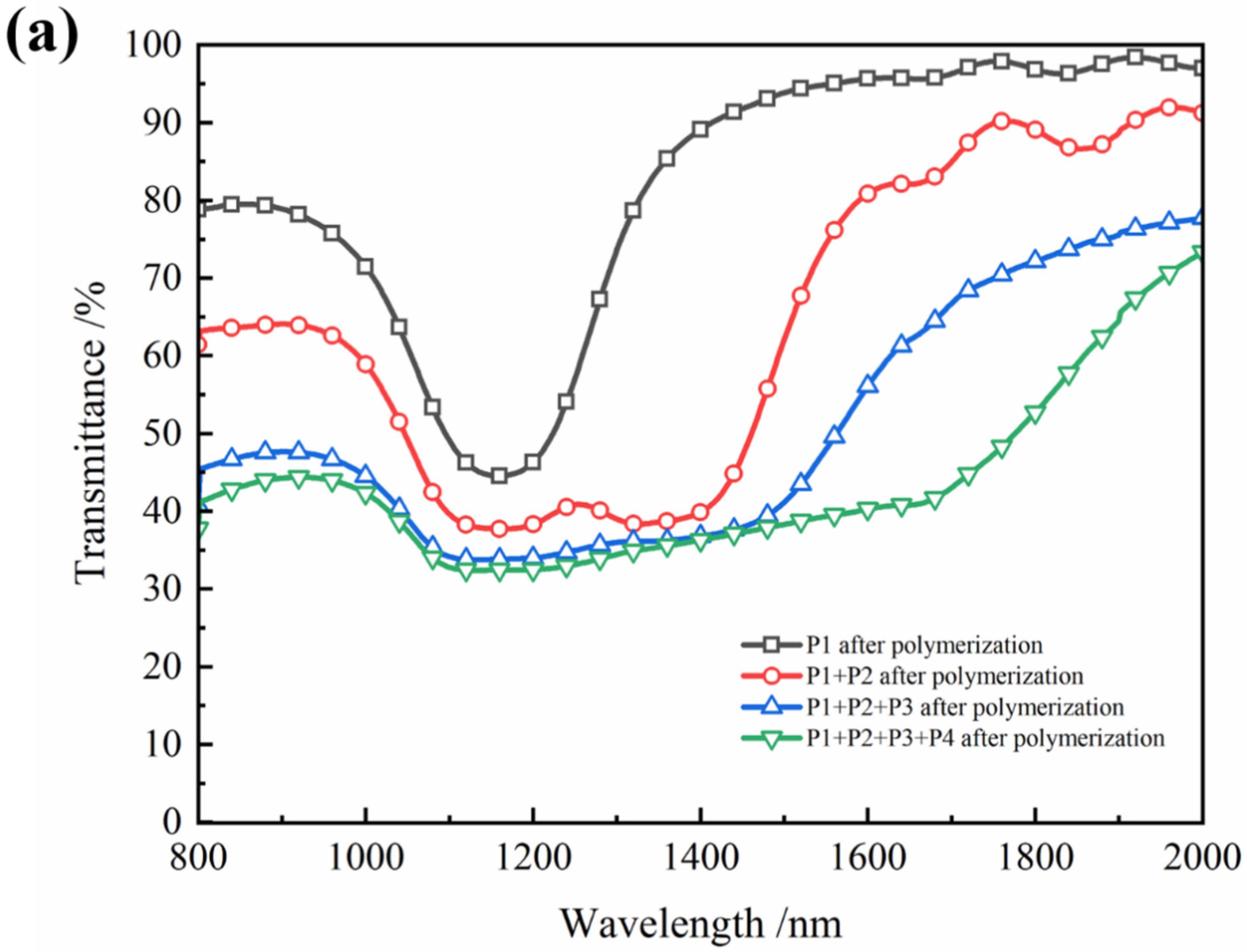
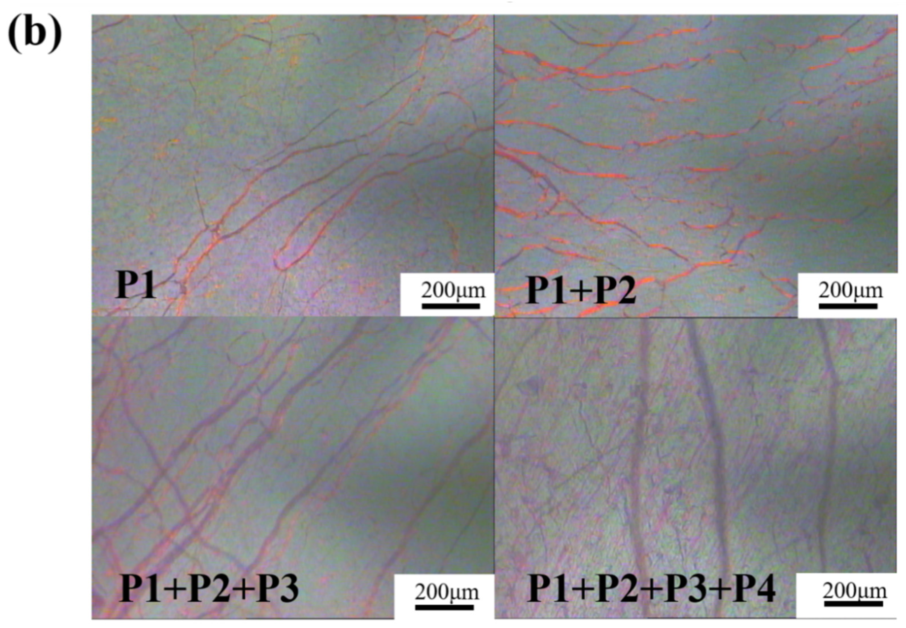
3.5. Method to Prepare the PSCLC Film with Wide-Band Reflection by IJP Technology

Four-layer Ch-LC films with 15 wt% C6M and different content of chiral dopant S811 were printed to prepare broadband reflective cholesteric films. The main components of each layer of Ch-LC film prepared by printing were shown in Table 3.
Figure 7 shows the change of the reflection bandwidth of the film as the number of printing layers increases. Curves 1, 2, 3, and 4 in the figure were the reflection spectrum of samples P1, P1 + P2, P1 + P2 + P3, and P1 + P2 + P3 + P4, respectively. It can be seen from the figure that the reflection bandwidth of the film changes from 1042–1270 nm to 1042–1508 nm after the second layer film was superimposed, which indicates that the chiral dopants near the substrate side of the first layer of PSCLC film almost does not diffuse, and the pitch of liquid crystal fixed by polymer network in this area does not change, so the reflection center wavelength of low band does not move. The films with high content of chiral dopants were polymerized first. The Ch-LCs with a low content of chiral dopants were diffused and the pitch was fixed after UV irradiation polymerization. Thus, the uneven distribution of chiral dopants was formed between each layer, and the gradient distribution of pitch was formed in the whole direction perpendicular to the film, and the polymer network was formed. Finally, a PSCLC film with broadband reflection from 1042 nm to 1845 nm was obtained by four-layer superposition. Figure 6 shows the liquid crystal texture images of PSCLC films with different layers. It can be seen that with the increase of layers, the interlacing of plane texture defects was more obvious, but each layer of films can maintain complete cholesteric plane texture, which verifies the feasibility of inkjet printing combined with the unsticking technique in the preparation of PSCLC films.

4. Conclusions

A new method for preparing broadband reflective cholesteric films based on inkjet printing and the unsticking technique was successfully developed. That is, the precursors of cholesteric liquid crystal films with different component ratios were quickly printed first by inkjet printing device, and then stacked and polymerized in situ by UV so as to form optical polymer cholesteric liquid crystal films as needed. It was found in our result that a wide band reflective liquid crystal film prepared by inkjet printing stack had a reflective band ranging from 1042 nm to 1845 nm. By comparing the central wavelength of the reflection spectrum of liquid crystal films prepared by manual mixing and by inkjet printing mixing, it was found that the accuracy of inkjet printing mixing was very high, with an error only less than 0.17 wt%. As known, the manual mixing method had some problems in the process of preparing samples, such as being time-consuming, having complex steps, and being error prone, while the inkjet printing method has been proven to solve these problems in the preparation process. Moreover, it could also simply and quickly prepare various complex patterns or large-area liquid crystal films and could quickly optimize the preparation of liquid crystal films with high throughput, which plays a positive role in scientific research and practical application.

Author Contributions

Conceptualization, W.H. and D.Y.; methodology, S.L.; software, S.L.; validation, D.Y., S.L. and R.X.; formal analysis, D.Y.; investigation, S.L.; resources, X.Y.; data curation, S.L.; writing—original draft preparation, S.L.; writing—review and editing, R.X.; visualization, X.Y.; supervision, X.Y.; project administration, W.H.; funding acquisition, X.Y. All authors have read and agreed to the published version of the manuscript.

Funding

This research received no external funding.

Institutional Review Board Statement

Not applicable for studies not involving humans or animals.

Acknowledgments

This work was supported by the National Key R&D Program of China (2018YFB0703703).

Conflicts of Interest

The authors declare no conflict of interest.

References

  1. Liu, S.; Li, Y.; Zhou, P.; Huang, S.; Chen, Q.; Su, Y. 51-3: A Multi-plane Optical See-through Head Mounted Display with Reverse Mode PSLC. SID Symp. Dig. Tech. Pap. 2017, 48, 763–766. [Google Scholar] [CrossRef]
  2. Fuh, A.Y.G.; Chih, S.Y.; Wu, S.T. Advanced electro-optical smart window based on PSLC using a photoconductive TiOPc electrode. Liq. Cryst. 2018, 45, 864–871. [Google Scholar] [CrossRef]
  3. Sun, H.; Xie, Z.; Ju, C.; Hu, X.; Yuan, D.; Zhao, W.; Shui, L.; Zhou, G. Dye-Doped Electrically Smart Windows Based on Polymer-Stabilized Liquid Crystal. Polymers 2019, 11, 694. [Google Scholar] [CrossRef] [Green Version]
  4. Khandelwal, H.; Schenning, A.P.; Debije, M.G. Infrared Regulating Smart Window Based on Organic Materials. Adv. Energy Mater. 2017, 7, 1602209. [Google Scholar] [CrossRef]
  5. Guo, J.; Wu, H.; Chen, F.; Zhang, L.; He, W.; Yang, H.; Wei, J. Fabrication of multi-pitched photonic structure in cholesteric liquid crystals based on a polymer template with helical structure. J. Mater. Chem. 2010, 20, 4094–4102. [Google Scholar] [CrossRef]
  6. Khandelwal, H.; Timmermans, G.H.; Debije, M.G.; Schenning, A.P. Dual electrically and thermally responsive broadband reflectors based on polymer network stabilized chiral nematic liquid crystals: The role of crosslink density. Chem. Commun. 2016, 52, 10109–10112. [Google Scholar] [CrossRef] [PubMed]
  7. Huang, Y.; Zhou, Y.; Wu, S.-T. Broadband circular polarizer using stacked chiral polymer films. Opt. Express 2007, 15, 6414–6419. [Google Scholar] [CrossRef]
  8. Kang, Y.J.; Bail, R.; Lee, C.W.; Chin, B.D. Inkjet Printing of Mixed-Host Emitting Layer for Electrophosphorescent Organic Light-Emitting Diodes. ACS Appl. Mater. Interfaces 2019, 11, 21784–21794. [Google Scholar] [CrossRef]
  9. Olivier, S.; Ishow, E.; Della-Gatta, S.M.; Maindron, T. Inkjet deposition of a hole-transporting small molecule to realize a hybrid solution-evaporation green top-emitting OLED. Org. Electron. 2017, 49, 24–32. [Google Scholar] [CrossRef]
  10. Kang, J.-G.; Koo, Y.; Ha, J.; Lee, C. Invited Paper: Recent Developments in Inkjet-printed OLEDs for High Resolution, Large Area Applications. SID Symp. Dig. Tech. Pap. 2020, 51, 591–594. [Google Scholar] [CrossRef]
  11. Marin, V.; Holder, E.; Wienk, M.M.; Tekin, E.; Kozodaev, D.; Schubert, U.S. Ink-jet printing of electron donor/acceptor blends: Towards bulk heterojunction solar cells. Macromol. Rapid Commun. 2005, 26, 319–324. [Google Scholar] [CrossRef]
  12. Holder, E.; Langeveld BM, W.; Schubert, U.S. New trends in the use of transition metal-ligand complexes for applications in electroluminescent devices. Adv. Mater. 2005, 17, 1109–1121. [Google Scholar] [CrossRef]
  13. Hoth, C.N.; Schilinsky, P.; Choulis, S.A.; Brabec, C.J. Printing Highly Efficient Organic Solar Cells. Nano Lett. 2008, 8, 2806–2813. [Google Scholar] [CrossRef] [PubMed] [Green Version]
  14. Alamán, J.; Alicante, R.; Peña, J.I.; Sánchez-Somolinos, C. Inkjet Printing of Functional Materials for Optical and Photonic Applications. Materials 2016, 9, 910. [Google Scholar] [CrossRef] [Green Version]
  15. Crowley, K.; O’Malley, E.; Morrin, A.; Smyth, M.R.; Killard, A.J. An aqueous ammonia sensor based on an inkjet-printed polyaniline nanoparticle-modified electrode. Analyst 2008, 133, 391–399. [Google Scholar] [CrossRef]
  16. Ma ZL, S.; Wang, H.T. Advanced electronic skin devices for healthcare applications. J. Mater. Chem. B 2019, 7, 173–197. [Google Scholar]
  17. Cull, T.; Goulding, M.; Bradley, M. A parallel high-throughput approach to liquid crystal screening. Rev. Sci. Instrum. 2005, 76, 062216. [Google Scholar] [CrossRef] [Green Version]
  18. Cull, T.R.; Goulding, M.J.; Bradley, M. Liquid Crystal Libraries—Ink-jet Formulation and High-Throughput Analysis. Adv. Mater. 2007, 19, 2355–2359. [Google Scholar] [CrossRef]
  19. Feng, W.; Li, L.; Du, X.; Welle, A.; Levkin, P.A. Single-Step Fabrication of High-Density Microdroplet Arrays of Low-Surface-Tension Liquids. Adv. Mater. 2016, 28, 3202–3208. [Google Scholar] [CrossRef] [Green Version]
  20. Dhanumalayan, E.; Joshi, G.M. Performance properties and applications of polytetrafluoroethylene (PTFE)—A review. Adv. Compos. Hybrid Mater. 2018, 1, 247–268. [Google Scholar] [CrossRef]
  21. Broer, D.J.; Lub, J.; Mol, G.N. Wide-band reflective polarizers from cholesteric polymer networks with a pitch gradient. Nature 1995, 378, 467–469. [Google Scholar] [CrossRef]
Figure 1. Chemical structure of LC monomer (C6M) and the chiral dopant (S811). (a) LC monomer. (b) Chiral dopant.
Crystals 12 00473 g001
Figure 2. (a) The printer after being modified; (b) the scheme of printing.
Crystals 12 00473 g002
Figure 3. (a) Cyan patterns with colorimetric value; (b) the “standard curves” of S811 ink; (c) the “standard curves” of SLC−1717 ink; (d) the “standard curves” of C6M ink.
Crystals 12 00473 g003
Figure 4. Comparison of the transmission spectra of the handmade sample (M) and the printed sample (P).
Crystals 12 00473 g004
Figure 5. The contact angle test results of ordinary glass substrate and PTFE modified glass substrate. (a) The ordinary glass substrate; (b) The glass substrate modified by PTFE.
Crystals 12 00473 g005
Figure 6. The crossed polarizing images of each layer of PSCLC film before and after stripping the upper substrate were as follows: (a,b) before and after the first layer of PSCLC film was removed from the substrate; (c,d) before and after the second layer of PSCLC film was removed from the substrate; (e,f) the PSCLC film before and after the stripping of ordinary glass substrate.
Crystals 12 00473 g006
Figure 7. Transmission curves (a) and polarizing images (b) of multilayer PSCLC.
Crystals 12 00473 g007aCrystals 12 00473 g007b
Table 1. Composition of the actual printed Ch-LC mixture.
Sample No.Print Formulation (wt%)
S811SLC-1717C6MIRG 651
P115.6168.3715.030.99
P213.8770.0915.031.01
P312.3871.5914.991.04
P410.9872.9515.021.05
P59.8174.1215.001.07
P68.6975.2714.951.09
P77.7076.1815.011.11
P86.8777.0214.991.12
Table 2. Composition of the hand mixed Ch-LC mixtures.
Sample No.Manual Formulation (wt%)
S811SLC-1717C6MIRG651
M115.5968.3715.060.99
M213.8970.0515.051.02
M312.2971.7614.921.03
M410.9773.0014.961.08
M59.8174.1314.971.10
M68.5875.4514.841.14
M77.5776.5314.781.12
M86.8577.2414.821.09
Table 3. Composition of Ch-LC films by ink jet printing.
Sample No.Print Formulation (wt%)
S811SLC-1717C6MIRG 651
P110.9872.9515.021.05
P28.6975.2714.951.09
P36.8777.0214.991.12
P46.1277.7515.001.13
Publisher’s Note: MDPI stays neutral with regard to jurisdictional claims in published maps and institutional affiliations.

