Article

Super Bonding Strength of Al2O3 Nanoparticles Reinforced Sn Interlayer Steel/Aluminum Bimetal Casting

1
College of Engineering, University of Ha’il, P.O. Box 2440, Hail 81441, Saudi Arabia
2
Central Metallurgical Research and Development Institute (CMRDI), P.O. Box 87, Helwan 11421, Egypt
3
School of Engineering, RMIT University, Melbourne, VIC 3000, Australia
4
Department of Physics, College of Science, University of Hail, P.O. Box 2440, Hail 81441, Saudi Arabia
5
Promising Centre for Sensors and Electronic Devices (PCSED), Advanced Materials and Nano-Research Centre, Najran University, P.O. Box 1988, Najran 11001, Saudi Arabia
*
Authors to whom correspondence should be addressed.
Crystals 2022, 12(3), 324; https://doi.org/10.3390/cryst12030324
Submission received: 5 February 2022 / Revised: 22 February 2022 / Accepted: 24 February 2022 / Published: 26 February 2022
(This article belongs to the Special Issue Advances in Nanocomposites and Alloys in Saudi Arabia)

Abstract

:
For specialized applications, it is incumbent to develop new materials that enable manufacturers to develop new processes and designs. For better fuel economy, structural integrity, and lightweight applications, the development of bimetallic steel/aluminum (Al) alloys having a strong interfacial bond is required. Therefore, a mild steel/Al-bearing alloy bimetallic composite was investigated in this study. Firstly, a tin (Sn) interlayer was developed between the steel substrate and the Al-bearing alloy by the tinning process. For further improvement in the interfacial integrity, alumina (Al2O3) nanoparticles were added to the Sn powder during the tinning process. Four different wt.% of Al2O3 nanoparticles of 0.25, 0.5, 1, and 1.5 were added and mixed thoroughly with Sn powder before mixing them with flux prior to the tinning process. Finally, molten Al-bearing alloy (Al–Sn-Si–Cu) was poured over the Al2O3 nanoparticles reinforced tinned steel substrate. A cross-section of the steel/Al-bearing alloy bimetallic composite was prepared for optical microscopy (OM), scanning electron microscopy (SEM), energy-dispersive X-ray spectroscopy (EDS), and shear testing. The cross-section microstructure of the steel/Al-bearing alloy bimetallic composite revealed irregular and discontinuous interfacial layers in the case of the low-temperature (170 °C) tinning process. However, a uniform, continuous interfacial layer was fabricated during the tinning process when additional preheat to the steel substrate and tinning process was adopted. It can be reported that low Al2O3 nanoparticles loading (0.25%) and steel substrate preheating were recommended for the better interfacial layer in the steel/Al-bearing alloy bimetallic composite.

1. Introduction

Nowadays, manufacturing techniques are more focused on fabricating materials of superior properties along with the facilitation of their fabrication techniques. Although several researchers [1,2,3] performed intensive development of cast metals structures and properties, the possibilities of the existing monometallic alloys are practically exhausted for fabricating new materials offering superior properties.
Liquid–solid compound casting has been used to fabricate different ferrous and nonferrous functionally grade materials, which was found to be the most economical fabrication technique that allows the fabrication of bimetal directly [4,5,6]. The higher bonding strength of bimetallic materials is still required to meet the demand of specialized applications. More attention should be given to improving the interfacial bonding strength of the metallic bearing material and the metallic substrate. Nanotechnology is a promising technology for the fabrication of products of determining functions. Nanomaterials are also used in cast metals (e.g., in cast metal structure with nanocrystalline precipitates) and in molding sand technologies, due to their special and superior effect of cast metal properties [7].
Ferrous alloys are still the most widely used metallic materials in casting processes [8,9,10,11,12]. The advantages of ferrous metals are that they are unique, low in cost, and stable in performance. Ferrous metals play significant roles in engineering manufacturing [13]. High-strength steel is an important engineering material for any national economy, national security, and a variety of key engineering areas.
The mechanisms of strengthening the metals are categorized as dislocation, grain refinement, solution strengthening, and second-phase dispersion, as well as phase transformation strengthening [14,15]. Although second-phase dispersion improves the strengths of the metals, the reduction in plasticity and/or toughness of the ferrous and nonferrous metals are often observed. It was reported [16,17] that the strength, along with toughness improvements of metals and alloys, could be achieved by grain refinement strengthening due to the influence of grain refining and pinning grain boundaries of the fine second phase particle to hinder coarsening of microstructure that can compensate toughness depreciation. Therefore, second-phase dispersion and grain refinement strengthening are considered the most important mechanisms for strengthening and toughening ferrous metallic materials [18].
Alloying, nucleating agents, as well as particles reinforcements, can be introduced and/or precipitated in the second phase in the matrix of steel. The strengthening effect of nanoreinforcement is relatively higher than microsized reinforcement. The high surface energy of nanosized reinforcements and variation in specific gravity for liquid ferrous metals and reinforcement make the dispersion and distribution of nanosized reinforcements in the ferrous metallic matrix relatively difficult to achieve [19]. The methods for introducing nanoparticles into ferrous materials (cast steel and cast iron) are classified into four categories: internal, external nanoparticle methods, in situ additive manufacturing, and reaction methods. Using nanoparticles as strengthening phase or nucleation phase, the lattice mismatch and valence electron between nanoparticles, and crystal structure matrix of steel are important criteria for strengthening effect and analyzing nucleation efficiency. During solidification of molten steel at higher temperatures, the different carbon content produces ferrite or austenite primary phase. Therefore, δ-Fe and/or γ-Fe are expected for nucleation. The effectiveness of heterogeneous nucleation and lattice mismatches relationship should be considered during the selection of nanoparticles suitable for the nucleating phase.
In two-layered bimetallic bearings, two metal alloys having different mechanical and wear properties are bonded together for heavyweights and stress-loading conditions. Two-layered bimetallic bearings are more suitable for medium-speed, medium-load, low-speed, and high-load situations. Bimetal bearings have the main functions of reducing friction and carrying loads of the shaft or any other axial and radial loading of moving parts. Low-carbon steel and stainless steel are commonly used as the base materials (substrates) in bimetallic bearings that are covered with Sn-based alloys, Al–Sn alloys, and Cu–Sn alloys on the exterior surface. The interfacial microstructure and the bond strength of bimetallic bearing materials were predominantly affected by substrate surface preparation, interlayer materials, and process parameters. The bonding quality of the bimetallic bearing materials fabricated by liquid–solid compound casting is dependent on various factors such as volume of liquid–solid ratio, the surface morphology of the solid substrate, and surface treatments of solid substrate [20,21,22,23]. Surface treatment of solid substrate could be performed by depositing a thin layer of Zn, Sn, and Al, using galvanizing, tinning, and aluminizing processes consequently [21,22,23,24].
In this study, Al2O3 nanoparticles reinforced Sn interlayer were investigated through changing the processing parameters with an ultimate objective to improve the bonding strength of aluminum/steel bimetallic casting.

2. Materials and Methods

2.1. Martials

Aluminum/steel bimetallic specimens were prepared using the compound casting technique. Table 1 shows the chemical compositions of the Al-bearing alloy and carbon steel substrate used for Al/Steel bimetallic composite fabrication.

2.2. Casting Process

Carbon steel specimen substrates of 90 × 25 × 5 mm3 were ground with emery papers of up to 800 grades. Steel specimen substrates were coated by pure tin and with a tin containing different percentages of alumina nanoparticles (50 nm). The direct pre-tinning process of the carbon steel substrate that involves powder tin, alumina nanoparticles, and flux mixture has been explained in detail elsewhere [25,26,27,28,29]. To study the process parameters on interfacial structure and bonding strength of Al/steel bimetallic casting, two different groups of bimetallic casting were prepared. In the bimetal A group, during the tinning process, steel substrates were heated at 350 °C for 120 s. For the bimetal B group, steel substrates were heated at 350 °C for 180 s, as shown in Table 2. A charge of 1.2 kg of Al-12Sn-4Si-1Cu bearing alloy was melted in an electrical furnace to 750 °C and 800 °C (heating rate = 10 °C/min.) in a graphite crucible for the bimetallic casting of group A and group B, respectively. After 30 min holding time, the molten Al alloy was poured on tinned carbon steel substrates, which were inserted into a preheated metallic mold at 170 °C and 350 °C. Figure 1 shows metallic mold steel substrate after cutting, steel substrate after grinding, steel substrate after tinning, the insertion of tinned steel substrate into the mold cavity, fabrication of bimetallic casting, and finally, the pouring process of molten Al-bearing alloy onto the metallic mold. Volume ratios of liquid Al-bearing alloy/solid carbon steel substrate were kept constant (VL/VS = 7) for all fabricated bimetallic castings. The tinned steel solid substrate strips for both bimetals A and B were preheated using a hot plate for 120 s and 180 s at 350 °C before pouring liquid Al alloy. Six different pre-tinning and process parameters conditions of steel solid substrates and Al-bearing alloy were performed, as shown in Table 3.

2.3. Microstructural Evaluations

For microstructural investigation, the specimens were cut, ground, polished, and etched with a solution consisting of 0.5 mL HNO3, 0.3 mL HCl, 0.2 mL HF and 19 mL H2O. An optical microscope (OM) (Olympus GX51, Tokyo, Japan) and field-emission scanning electron microscope (FESEM) (JEOL-6300F, 5 KV) coupled with energy-dispersive X-ray spectroscopy (EDS) scanning electron microscope (SEM) was used to investigate bimetallic materials and their interfacial structure. The chemical compositions of the bimetallic interfaces were measured by energy-dispersive X-ray spectroscopy (EDS).

2.4. Mechanical Characterizations

The shear strength value of the interface of the bimetallic specimen was performed using a universal tensile testing machine (Instron 5969, Instron with a maximum load of 50 KN, Norwood, MA, USA), as discussed in a previous study, along with the dimensions of the tensile–shear specimen [30]. All shear tests were performed at a constant strain rate of 0.5 mm/min to the failure of the specimens. Three specimens were tested to determine the average shear strength value.

3. Results

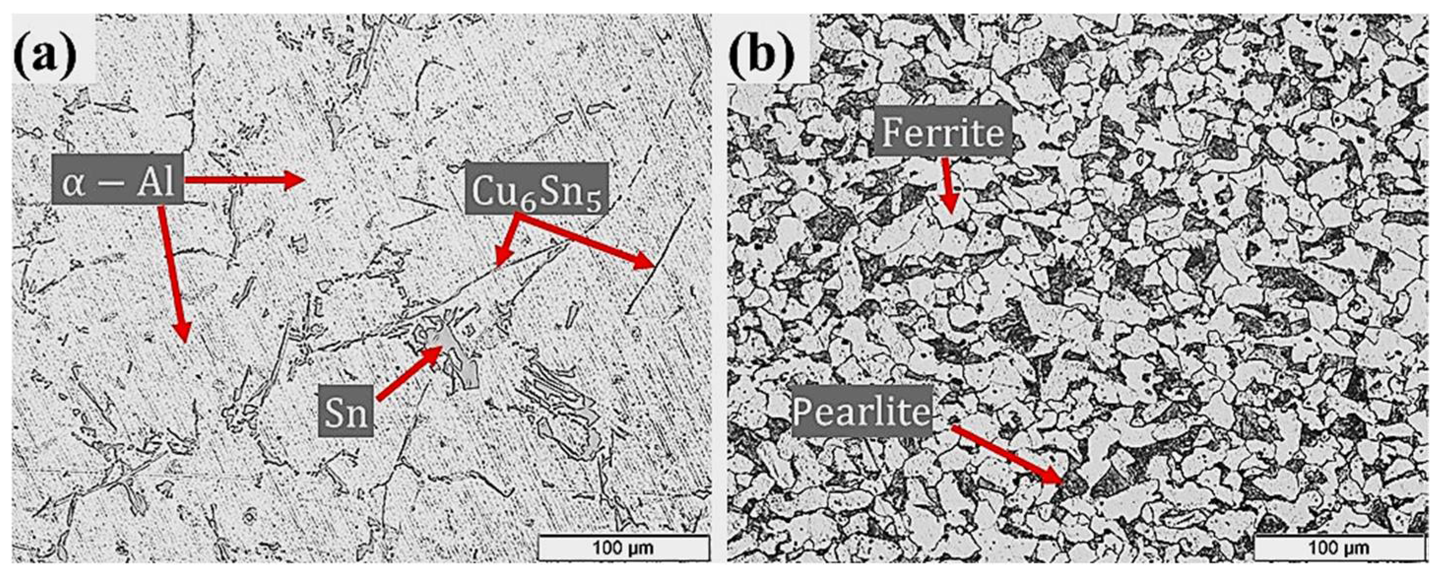
3.1. Microstructure and Mechanical Properties of Starting Materials

Tension strengths and hardness’s of Al–Sn bearing alloy (110 ± 5 MPa and 36.40 ± 5.6 HRF) and carbon steel substrate (410 ± 10 MPa, 102.48 ± 9.5 HRF) used for bimetallic fabrication were measured according to (ASTM E8). Typical microstructures of the Al-bearing alloy and low carbon steel are shown in Figure 2. The alloying elements Si and Sn have limited solubility in Al at room temperature. Such elements precipitate as separate phases (Sn and Si) during the solidification process. Hence, δ-Sn and δ-Si segregate at the dendritic regions of α-Al, as shown in Figure 2a. Binary intermetal of Cu–Sn (Cu6Sn5) is also present as high aspect ratio particles. The mild carbon steel optical microstructure is shown in Figure 2b, which reveals typical ferrite and pearlite phases. Figure 2b shows a typical microstructure of the mild steel substrate used in this study. The relative proportion of ferrite (white phase) and pearlite (black phase) confirms C contents in the steel.
SEM and EDS analyses of the Al-bearing alloy are given in Figure 3. The black regions represent α-Al, whereas the white spots depict Sn, and Si precipitates. Figure 3b reveals the qualitative chemical composition of the Al matrix that is predominantly composed of Al in addition to Si, Sn, and Cu. The white regions EDS analysis reveals that Sn is the main precipitated phase in the α-Al interdendritic regions. Si phase also precipitates in a similar fashion. The needle-like phases are most likely Cu2Al and Cu6Sn5, which are shown in Figure 3a.

3.2. Effect of Casting Process Parameters

In the present study, two casting parameters were investigated that are outlined in Table 2. For both bimetals A and B, a pure tin layer was developed on the steel substrate using the tinning process. For bimetal A (designated as S0), tinning was carried out at 350 °C for 120 s. The tinned steel substrate was preheated to 350 °C for 120 s before placing it in the preheated mold (170 °C). The final step involved the pouring of molten Al-bearing alloy at 720 °C on the tinned steel substrate. The whole assembly was then allowed to cool naturally. A cross-section of the bimetal A was prepared for metallography study. Figure 4a shows the OM image of the bimetal A (S0) cross-section composed of the steel substrate, interfacial alloy layer, and Al-bearing alloy. The interfacial alloy layer morphology revealed that the adhesion between the steel substrate and Al-bearing alloy is uneven and discontinuous. This suggests marginal wetting between substrate and coating alloy that resulted in a poor interfacial bond. In Figure 4a, unbonded interfacial regions are evident. Overall, the thickness of the interfacial alloy layer is <4–5 µm. The interfacial alloy layer is most likely composed of Al–Fe (Al3Fe and Al5Fe2) intermetallic compounds, as reported by previous researchers [31].
Figure 4b shows the OM image of bimetal B (S1). A similar tinning process produced this bimetal; however, 180 s was the holding time. Moreover, 350 °C for 180 s was the preheating temperature. In addition to that, mold was preheated to 350 °C prior to pouring of the molten Al-bearing alloy at 770 °C. The solidification and samples preparation procedures were unchanged. Typical microstructures of mild carbon steel substrate and Al-bearing alloy, in addition to interfacial alloy layer, were observed, as shown in Figure 4b. Contrary to bimetal A, the interfacial alloy layer formed in bimetal B is uniform and continuous. It has been reported earlier that the FeSn2 layer formed during the tinning process [28]. The additional supplied heat facilitated molten Al mass transfer to the steel substrate through the molten Sn/FeSn2 layer. As a result, Al and Fe reacted, developing an alloy layer composed of Al3Fe/Al5Fe2 between the steel substrate and Al-bearing alloy. One study reported in the literature [32] suggested that the chemical reaction between Al and Fe is extremely fast and, therefore, is not the rate-limiting factor. However, in most cases, mass transfer of Al and Fe are the rate-limiting factors, as observed in this study.
The processing parameters significantly affected the morphology and thickness of the interfacial alloy layer. The bonded areas for both processing conditions (bimetal A and bimetal B) were calculated and are shown in Figure 5. The percentage of bonded area for bimetal B is much higher than that in bimetal A. An increase of 33% bonded area in the case of bimetal B supports the argument that diffusion of the molten Al atoms through the liquid Sn layer facilitated for homogenous and regular interfacial alloy layer.
A shear stress test is used to investigate the integrity of the interfacial alloy layer developed in a bimetal composite material. Figure 6 shows the influence of the processing parameters (Table 2) on the shear stress endurance of the interfacial alloy layer formed in the Al-bearing alloy and mild steel composite. An extraordinary difference in the shear stress–strain behavior of both processing conditions was recorded, which is evident from Figure 6. For the processing condition “A” (bimetal A), the Al-bearing alloy/mild steel composite failed at only 8 MPa shear stress with only 0.02 shear strain. However, for the processing condition “B” (bimetal B), the same bimetal composite failed at >30 MPa shear stress, with 0.11 shear strain. This is an increase of >280% in shear stress and >500% in the shear strain, which is a remarkable finding of this study.
A comparative analysis of the processing conditions A and B suggested that the bimetal fabricated adopting route B produced a regular and uniform interfacial compound layer. This resulted in a larger bonded area between the Al-bearing alloy and mild steel bimetal composite. Hence, Al-bearing alloy/mild steel composite with significantly superior mechanical properties was successfully fabricated in this study. Therefore, bimetal B was selected for further study, in which different loadings of Al2O3 nanoparticles were performed to fabricate nanocomposites interlayer bimetallic materials.

3.3. Effect of Alumina Nanoparticle-Reinforced Sn Interlayer

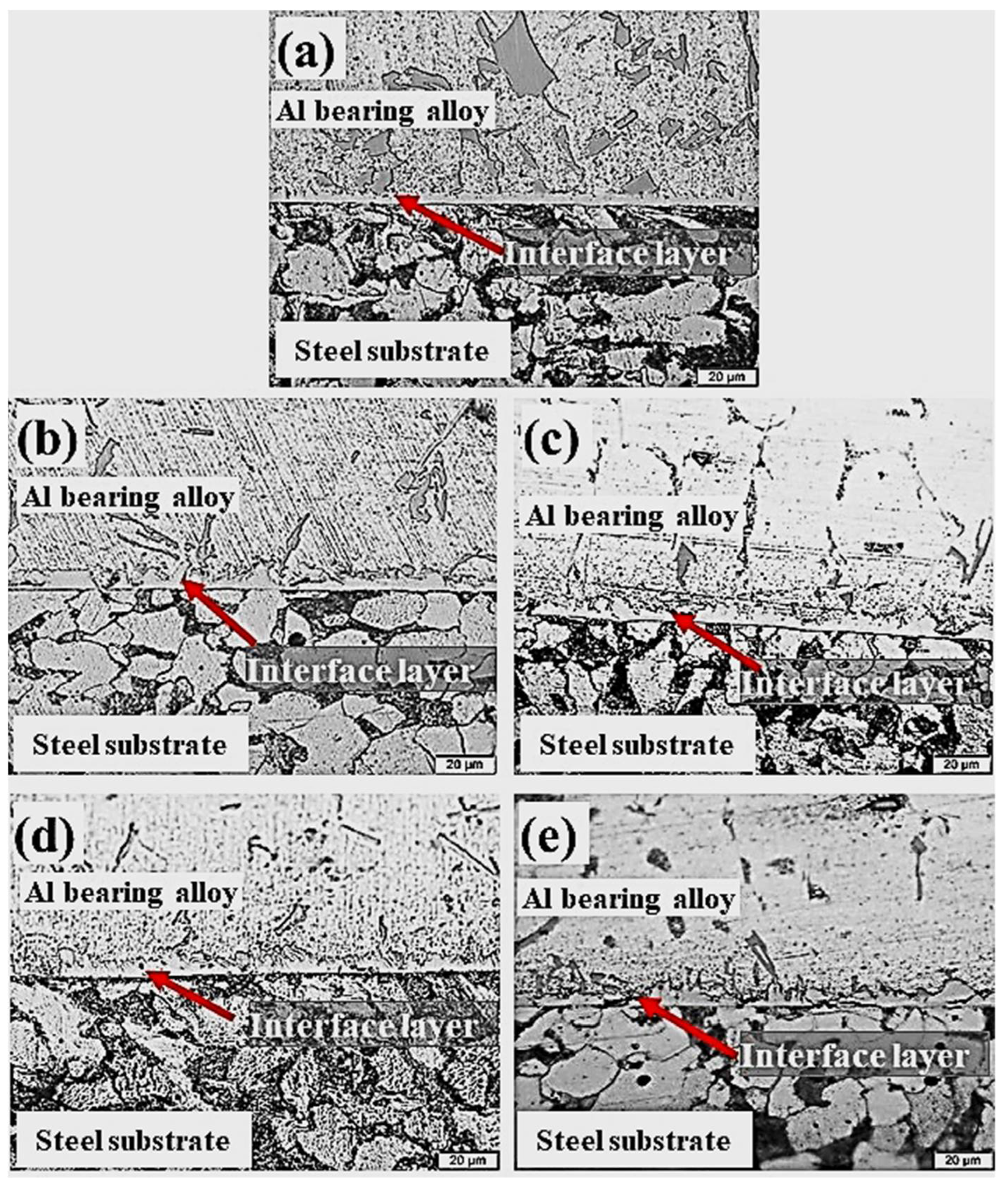
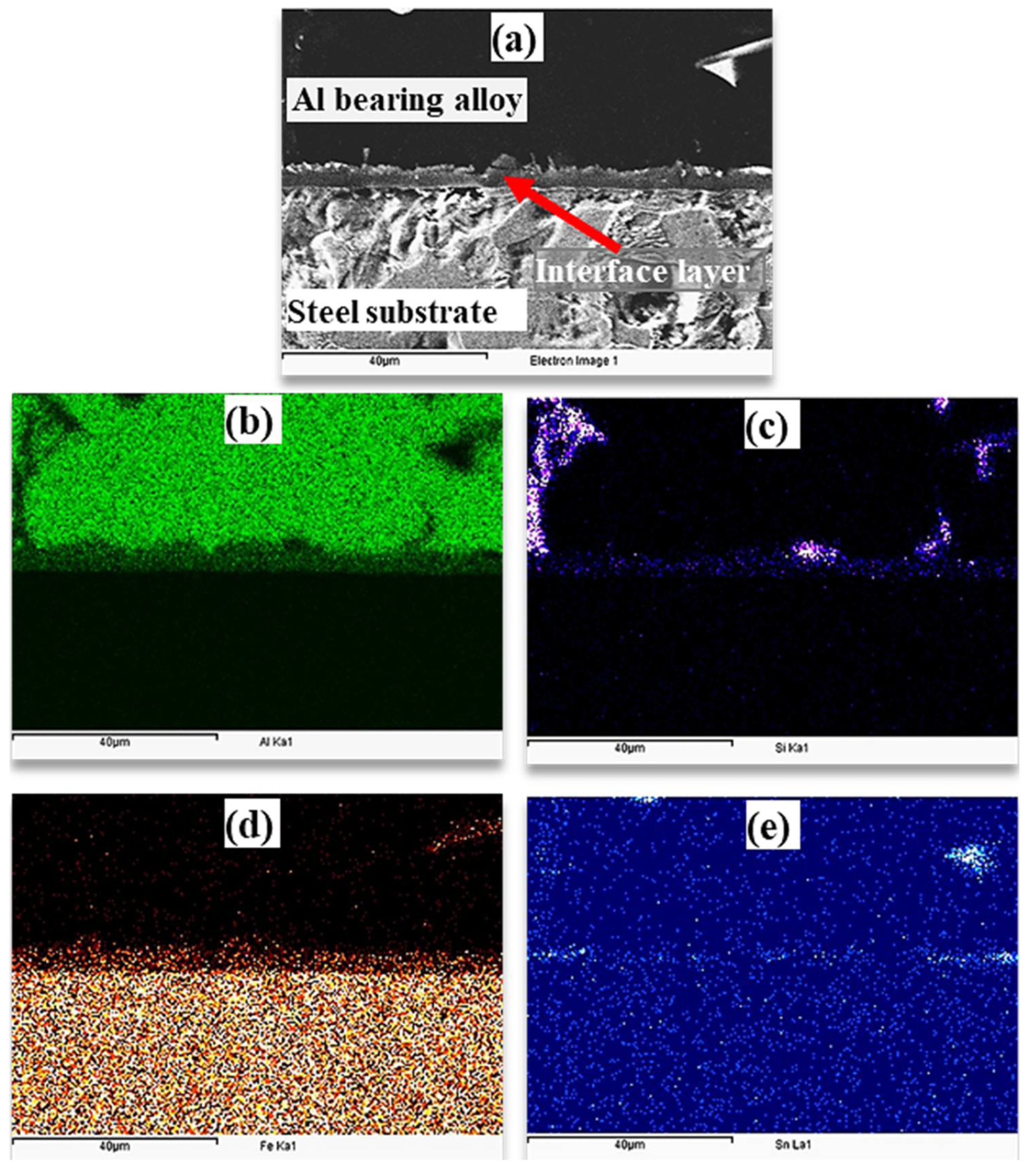
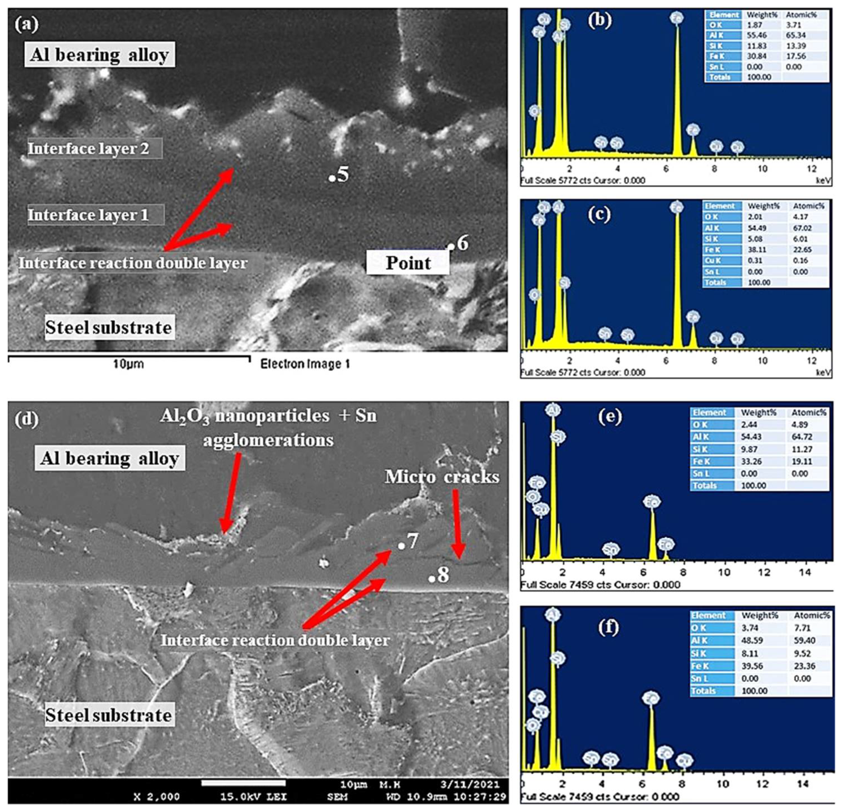
3.3.1. Microstructure and Interface Structure

This section outlines the influence of Al2O3 nanoparticles loadings on the morphology and microstructure of an interfacial layer structure formed between Al-bearing alloy and mild steel bimetal composite. Table 3 outlines experimental details for the development of Al2O3 nanoparticles loaded in nano bimetallic composites. Figure 7 shows OM images of the cross-sections of mild steel substrate coated with Al-bearing alloy and Sn only (S1), and with 0.25% (S2), 0.50% (S3), 1% (S4), and 1.50% (S5) Al2O3 nanoparticle-loaded Sn interlayers. It is worth noting that the interfacial layer microstructure and morphology were significantly influenced by adding the Al2O3 nanoparticles in the Sn interlayer between Al-bearing alloy coating and mild steel substrate. An increase in the interfacial layer thickness by adding Al2O3 nanoparticles was observed, as shown in Figure 7b–d. Moreover, the interfacial alloy layer formed is also regular and uniform over the entire Al-bearing and mild steel substrate interface. However, further increase in Al2O3 nanoparticles to 1.50% resulted in the uneven and irregular morphology of the interfacial layer, as shown in Figure 7e.
Change in the thickness of the interfacial intermetallic compound (IMC) layer with Al2O3 nanoparticles is shown in Figure 8. It is evident that the interfacial layer thickness increased with increasing the Al2O3 nanoparticles from 0% to 1%. A further increase in Al2O3 nanoparticles resulted in a decline in the interfacial layer thickness, as shown in Figure 8. Tikale and Prabhu [33] investigated the influence of Al2O3 nanoparticles on the wetting and mechanical properties of low Ag lead-free SAC0307 solder alloy. An increase in wetting area, microhardness, and shear strength with low addition (from 0.01% to 0.50%) of Al2O3 nanoparticles was reported. The findings of this study are in agreement with those reported in the literature [33].
It is suggested that the low addition of Al2O3 nanoparticles increased wetting of the Sn and mild steel substrate, which facilitates a better interlayer bond. Subsequently, during the casting of molten Al-bearing alloy over Al2O3 nanoparticles, the doped Sn layer facilitated the Al mass transfer to the steel substrate, where the following chemical reactions are inevitable [34,35,36,37,38]:
Fe + 2Sn = FeSn2
2Fe + 5Al = Fe2Al5
Fe + 3Al = FeAl3
Fe + Al + Si = FeAlSi
During the tinning process, Fe–Sn interfacial layer is developed. According to the Fe–Sn binary phase diagram, FeSn2, FeSn, Fe3Sn2, Fe6Sn3 are the possible phases [38]. However, FeSn2 is commonly observed in the interface of tinned steels products. FeSn2 intermetallic is stable up to 496 °C, which contains 80.95% Sn [36,38]. It was expected that the FeSn2 layer would dissolve during the pouring of liquid Al bearing alloy at 770 °C. Reaction (1) was expected during the tinning process in this study. During the pouring of the molten Al-bearing alloy over the tinned steel substrate, reactions (2) were inevitable, developing the interfacial layer. However, by increasing Al2O3 nanoparticles loadings, reaction (3) was also observed, which developed the second interfacial layer. The formation of FeAlSi IMCs according to Equation (4) was also possible, which has also been reported by earlier studies [31]. At low Al2O3 nanoparticles loading, there is an increase in interfacial layer growth because nanoparticles are most likely embedded within the interfacial layer structure. However, at higher Al2O3 nanoparticles loading, agglomeration obstructs the interfacial layer growth. As a result, the interfacial layer is irregular and less thickened. An optimum Al2O3 nanoparticles loading of a maximum of 0.25% is one of the key findings of this study. Elemental mapping of the Al-bearing alloy and mild steel bimetal cross-section in the case of pure Sn interlayer was obtained through the EDS analysis, which is presented in Figure 9. An SEM–SEI image of a cross-section showing Al-bearing alloy, interfacial layer, and mild steel substrate is given in Figure 9a. The corresponding elemental maps of Al, Si, Fe, and Sn are shown in Figure 9b–e.
It is clear that Al-bearing alloy is composed of Al, Si, and Sn, and steel substrate is composed of Fe, as expected. Additionally, it is evident from Figure 9 that the interfacial layer contains Al, Fe, and Si, with Sn segregation within the interlayer region. There is evidence of FeAlSi and Sn intermetallic particles but is difficult to distinguish at this stage.
EDS analysis was used to obtain interfacial layer point analysis, shown in Figure 10, Figure 11 and Figure 12. Interfacial layer point analysis, shown in Figure 10b,c, corresponds to points 1 and 2, shown in Figure 10a. Al, Si, Fe, and Sn are the main components of the interfacial alloy layer. It is worth noting that the chemical composition of the interfacial alloy layer is uniform entirely. Therefore, it is suggested that the entire interfacial layer is composed of only one type of Al5Fe2/α-AlFeSi IMCs particles. Such Fe-based IMCs particles have been reported in the Al–Zn–Si coating alloy [34].
Generally, FeAl3 and Fe2Al5 are common IMCs phases observed in the Al and –Zn–Si coated steel products. Fe5Si2Al20 phase has been reported in the literature [31,32,33], which formed in the case of poorly coated steel samples. It is suggested, based on the point analysis, that the interfacial alloy is composed of FeAl3 or α-FeAlSi phase (Table 4). EDS analysis of Points 3 and 4 of Figure 10d are shown in Figure 10e,f. Similar to S0, the interfacial alloy layer is composed of only one type of IMCs, which is most likely Al4.5SiFe, in addition to Al2O3 nanoparticles. The highly charged white spots in Figure 10d are Al2O3 nanoparticles that are embedded within the interfacial layer.
The interfacial layer of samples S3 and S4 SEM–SEI images and EDS point analysis are shown in Figure 11. Surprisingly, two interfacial layers were observed by increasing Al2O3 nanoparticles from 0.25% to 0.50% and above. Interfacial layer 1 was formed between the steel substrate and interface layer 2, which was formed between Al-bearing alloy and interface layer 1, as shown in Figure 11a. The interfacial alloy layer 1 is most likely FeAl3 based on the EDS and Fe–Al binary phase diagram. It should be noted that Si plays a significant role in altering the crystallography of Al3Fe, and hence, α-Al8Fe2Si IMC is possible in layer 1. The interfacial alloy 2 is Al5Fe2 and Al8Fe2Si, as given in Table 4. Previous researchers have reported the formation of Al3Fe adjacent to the steel surface and Al5Fe2 adjacent to the Al–Zn–Si coating alloy [39]. FeAlSi (α-Al8Fe2Si/α-Al167.8Fe44.9Si23.9 IMC precipitation is also inevitable in the Al-bearing alloy containing Si [26]. In addition to the formation of two interfacial layers, Al2O3 nanoparticles are also present within the layers, added initially in the Sn interlayer.
Figure 12 shows SEM–SEI and EDS analysis of the mild steel/Al-bearing alloy composite containing 1.50% Al2O3 nanoparticles in the Sn interlayer. Similar to samples S3 and S4, two interfacial alloy layers were observed in this sample (S5). AlFe3 and α-AlFeSi IMCs are dominated in interface layer 2, and Al5Fe2 and α-AlFeSi are found in interface layer 2, which is adjacent to the Al-bearing alloy. Additionally, Al2O3 nanoparticles agglomerates and Sn precipitates (point 9) were also observed, as shown in Figure 12. Microcracks formation at the interfacial boundary layers 1 and 2 interface is yet another microstructural feature observed in this study, as shown in Figure 11d and Figure 12a. A similar microcracks formation has been reported in the literature [40] during the study of 316 L stainless steel immersion in the Al–Zn–Si coating alloy. The interfacial layers formed are hard and brittle phases and hence tend to fracture at their interfaces [40]. This is one of the key parameters that contribute to the bottom dross build-up in a galvanizing bath.

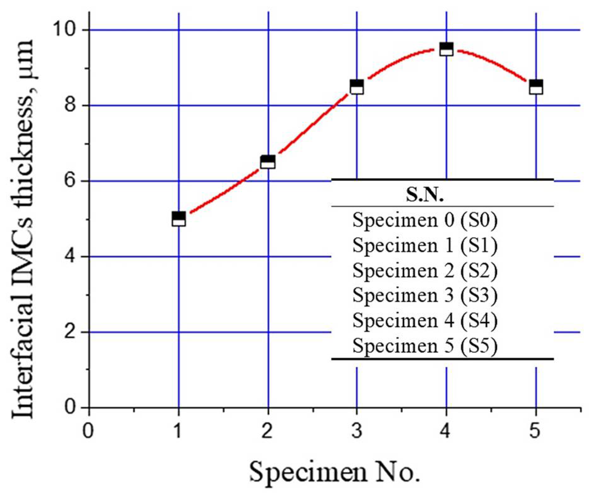
3.3.2. Interfacial Mechanical Properties

The interfacial strength of the mild steel/Al-bearing alloy composites with various types of Sn + Al2O3 nanoparticles interlayers was analyzed with a shear test. Figure 13 shows all samples (S0 to S5) shear strength plots. A drastic increase in the shear strength by improving the processing parameters is evident, improving the shear strength from ~8 to ~30 MPa (S0 and S1). The regular and uniform interfacial layer development is responsible for the improved shear strength. Moreover, shear strength increased by adding Al2O3 nanoparticles in the Sn interlayer, as observed for S3. A low Al2O3 nanoparticles addition in the Sn interlayer improved wetting between the mild steel substrate and Al-bearing alloy. Eventually, the shear strength of the bimetal composite containing Sn + 0.25% Al2O3 nanoparticles increased by ~6%. Further increase in the Al2O3 nanoparticles loading did not result in the same effect and even decreased the shear strength, as shown in Figure 13. By increasing Al2O3 nanoparticles loading to 0.50%, shear strength declined by 43%. Two factors are responsible for the decline in the shear strength of high Al2O3 nanoparticles bimetal composites: (1) uneven Al2O3 nanoparticles distribution and agglomeration in the interfacial layer and (2) development of two types of interfacial layers. Both of these factors significantly reduced the shear strength of the high Al2O3 nanoparticle-loaded bimetallic composites. During mechanical loading, Al2O3 nanoparticles agglomerates act as weak regions, where localized stress exceeds the fracture strength of the interfacial IMC layer. In addition to that, two IMC interfacial layers formation is not recommended for better integrity of the mild steel/Al-bearing alloy bimetallic composite. As reported earlier, interfacial layers are much harder and brittle, compared with the substrate and coating alloy, hence observing different mechanical behavior under applied load. The modulus of elasticity for mild steel substrate, interfacial layers (1,2), and Al-bearing alloy are different. Moreover, microcracks development between interfacial layers 1 and 2 are also a weak point that can facilitate earlier failure, hence lowering the shear strength.
Table 5 summarizes the shear strength of the steel and Al bimetal composite having various interlayer materials and casting processes. The Sn and Sn + 0.25%Al2O3 nanoparticles interlayer mild steel/Al-bearing alloy bimetal composite showed comparable shear strength with the Zn + 0.2% Bi interlayer Fe/Al bimetallic composites. Much higher shear strength of mild steel/Al-bearing alloy was obtained in this study, compared with most of the similar bimetal composites, as outlined in Table 5.

4. Conclusions

In the present study, a steel/Al-bearing alloy bimetallic composite was developed with different loadings of Al2O3 nanoparticles. The tinning process was optimized prior to the loading of Al2O3 nanoparticles for better interfacial alloy development. The following features were the key findings of this study:
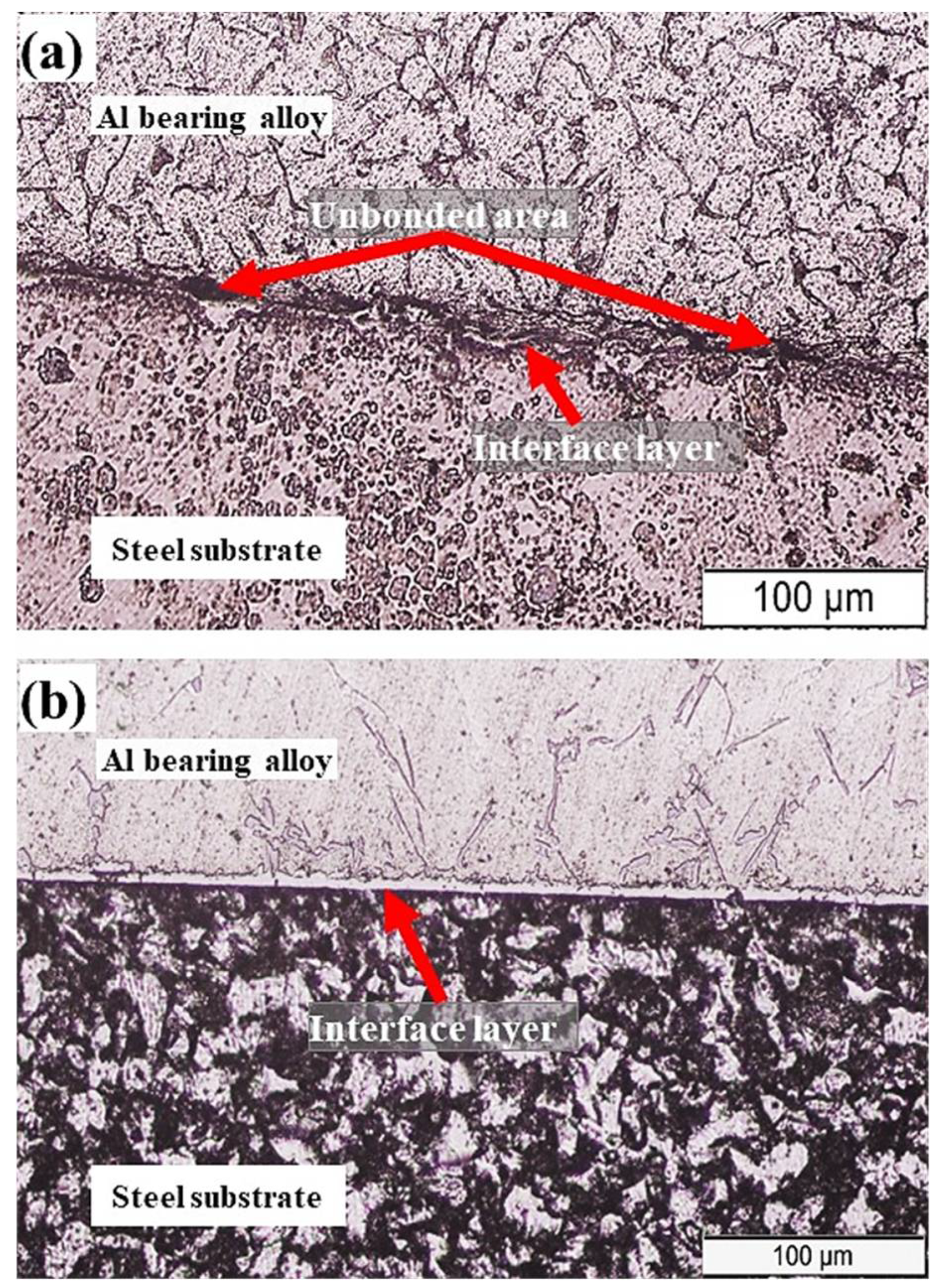
  • The interfacial layer developed during tinning was composed of FeSn2 that was stable up to a temperature of 496 °C [37]. In the case of low mold preheating (170 °C) and molten Al-bearing alloy (720 °C), the interfacial layer was irregular and not fully coherent and continuous. However, by increasing the mold’s preheating temperature to 350 °C and Al-bearing alloy melting temperature to 770 °C, a regular, coherent, and continuous interfacial layer was successfully developed.
  • An increase in Al-bearing alloy pouring temperature and mold preheat potentially dissolved the FeSn2 layer. Consequently, mass transfer of the Al to the steel substrate increased, leading to the formation of a regular and continuous interfacial layer. The interfacial layer formed between the steel/Al-bearing composite was composed of Al5Fe2, in agreement with previous studies.
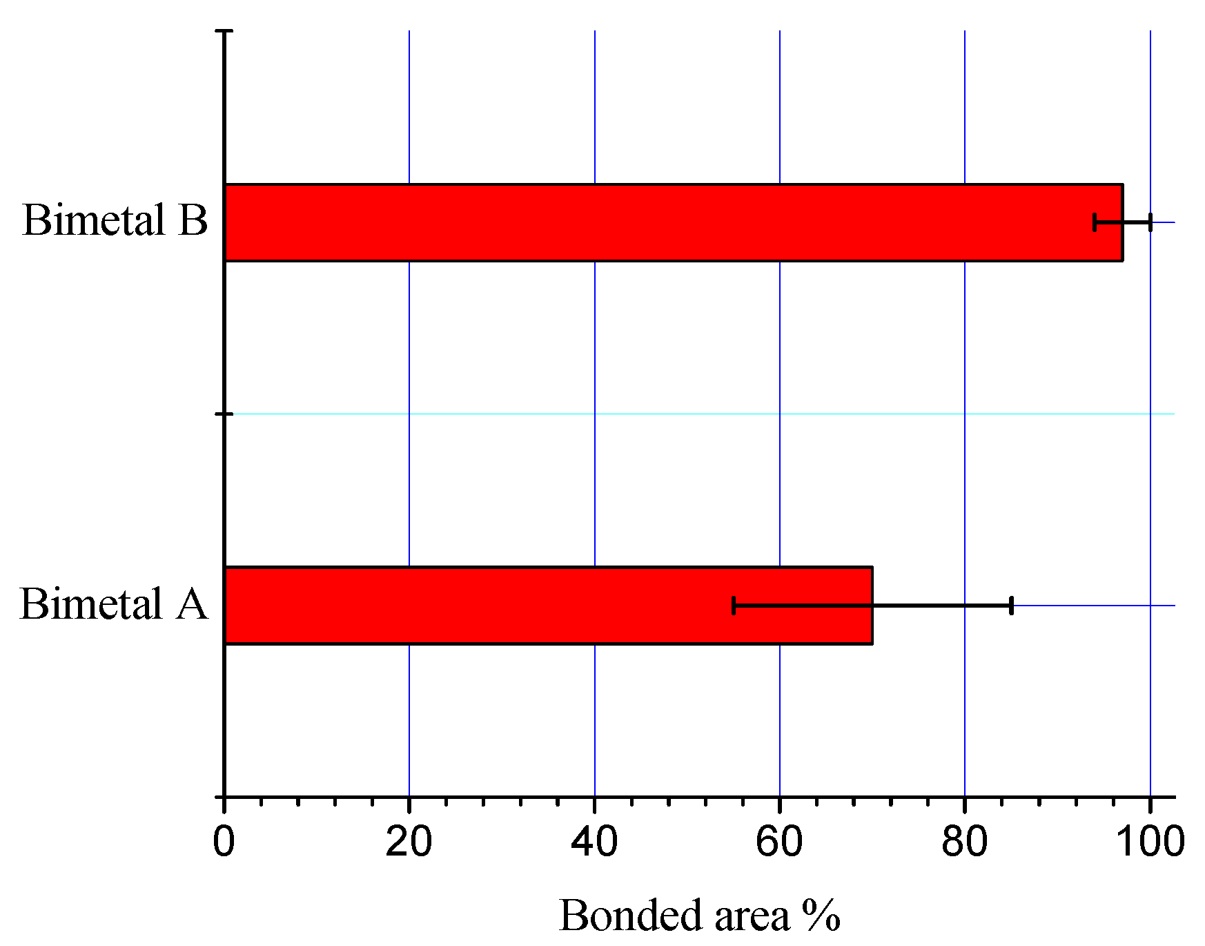
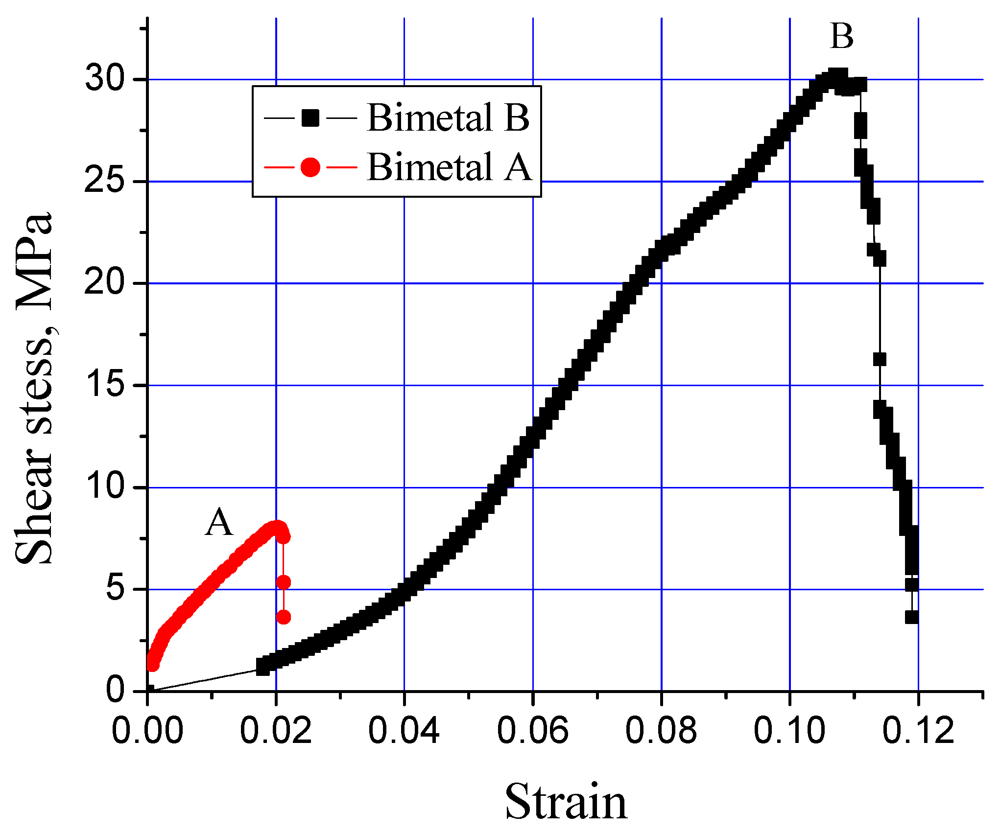
  • By improving the process parameters, the shear strength of the steel/Al-bearing alloy surprisingly increased by 500%. The increase in the shear strain was 280%, which is also an extraordinary finding of this study.
  • Further increase in the shear strength was recorded by loading 0.25% Al2O3 nanoparticles in the Sn layer, and the findings are in agreement with the previous studies.
  • Higher Al2O3 nanoparticles loadings (0.50% to 1.50%) are not recommended due to Al2O3 nanoparticles agglomerations between the interfacial layer and Al-bearing coating. Such microstructural discrepancies are sources of failure in materials, as they act as stress raiser points during loading.
  • Two types of interfacial layers composed of AlFe3 and Al5Fe2 were observed by increasing Al2O3 nanoparticles loadings to 0.50% and beyond. Heat accumulation and coating time are two key factors that facilitate the development of two layers instead of one. Moreover, AlFe3 formed adjacent to the steel substrate, and Al5Fe2 formed close to the Al-bearing alloy.

Author Contributions

Conceptualization, M.R., K.S.A.H. and A.K.; methodology, M.R. and K.M.H. validation, M.R., A.S.A., N.F. and A.K.; formal analysis, M.R., A.K. and N.F.; investigation, F.A.H., B.A. and K.M.H.; resources, N.F., M.R. and B.A.; data curation, M.R. and A.K.; writing—original draft preparation, M.R. and A.K.; writing—review and editing, A.S.A., K.M.H., K.S.A.H. and F.A.H.; project administration, A.S.A. All authors have read and agreed to the published version of the manuscript.

Funding

This research has been funded by the Scientific Research Deanship at the University of Ha’il—Saudi Arabia through project number RG-20074.

Data Availability Statement

Data available in a publicly accessible.

Conflicts of Interest

The authors declare no conflict of interest.

References

  1. Ramadan, M.; El-Bagoury, N.; Fathy, N.; Waly, M.A.; Nofal, A.A. Microstructure, fluidity, and mechanical properties of semi-solid processed ductile iron. J. Mater. Sci. 2011, 46, 4013–4019. [Google Scholar] [CrossRef]
  2. Ramadan, M.; Nofal, A.A.; Elmahalawi, I.; Abdel-Karim, R. Influence of graphite nodularity on microstructure and processing window of 1.5% Ni-0.3% Mo austempered cast iron. Mater. Sci. Eng. A 2006, 435, 564–572. [Google Scholar] [CrossRef]
  3. Ramadan, M.; Fathy, N. Solidification microstructure of rheocast hyper-eutectic Al–18Si alloy. J. Metall. Eng. 2013, 2, 149–153. [Google Scholar]
  4. Gawronski, J.; Szajnar, J.; Wro’bel, P. Study on theoretical bases of receiving composite alloy layers on surface of cast steel castings. J. Mater. Process. Technol. 2004, 157, 679–682. [Google Scholar] [CrossRef]
  5. Tayal, R.K.; Kumar, S.; Singh, V.; Garg, R. Characterization and microhardness evaluation of A356/Mg joint produced by vacuum-assisted sand mold compound casting process. Int. J. Metalcast. 2019, 13, 392–406. [Google Scholar] [CrossRef]
  6. Tayal, R.K.; Kumar, S.; Singh, V.; Gupta, A.; Ujjawal, D. Experimental investigation and evaluation of joint strength of A356/ Mg bimetallic fabricated using compound casting process. Int. J. Metalcast. 2019, 13, 686–699. [Google Scholar] [CrossRef]
  7. Kmita, A.; Dańko, R.; Holtzer, M.; Hutera, B.; Stypuła, B. Utilisation of nanoparticles in technologies of producing castings for the needs of power engineering. Nanomater. Energy 2014, 3, 53–60. [Google Scholar] [CrossRef]
  8. Bawane, K.; Lu, K. Microstructure evolution of nanostructured ferritic alloy with and without Cr3C2 coated SiC at high temperatures. J. Mater. Sci. Technol. 2020, 43, 126–134. [Google Scholar] [CrossRef]
  9. Jiang, S.H.; Wang, H.; Wu, Y.; Liu, X.; Chen, H.; Yao, M.; Gault, B.; Ponge, D.; Raabe, D.; Hirata, A.; et al. Ultrastrong steel via minimal lattice misfit and high-density nanoprecipitation. Nature 2017, 544, 460–464. [Google Scholar] [CrossRef] [PubMed]
  10. Rodríguez, E.; Pérez, A.; Mercado-Solis, R.D.; Abraham, V.-T.; Jiménez, O.; Flores, M.; González, M.A.; Ibarra, J. Erosion problem in tool steel using cold box core-making process. China Foundry 2019, 16, 204–210. [Google Scholar] [CrossRef] [Green Version]
  11. Han, X.; Zhang, Z.P.; Hou, J.Y.; Barber, G.C.; Qiu, F. Tribological behavior of shot peened/austempered AISI 5160 steel. Tribol. Int. 2020, 106197, 145. [Google Scholar] [CrossRef]
  12. Li, H.C.; Liu, Y.X.; Zhang, Y.H.; Liu, Z.; Zhai, Q.-J. Effects of hot top pulsed magneto-oscillation on solidification structure of steel ingot. China Foundry 2018, 15, 110–116. [Google Scholar] [CrossRef] [Green Version]
  13. Hao, L.H.; Ji, X.; Zhang, G.Q.; Zhao, W.; Sun, M.; Peng, Y. Carbide precipitation behavior and Mechanical properties of micro-alloyed medium Mn steel. J. Mater. Sci. Technol. 2020, 47, 122–130. [Google Scholar] [CrossRef]
  14. Liu, Y.C.; Liu, C.X.; Sommer, F.; Mittemeijer, E.J. Martensite formation kinetics of substitutional Fe–0.7at.% Al alloy under uniaxial compressive stress. Acta Mater. 2015, 98, 164–174. [Google Scholar] [CrossRef]
  15. Zhang, H.J.; Li, C.; Guo, Q.Y.; Ma, Z.; Li, H.; Liu, Y. Improving creep resistance of nickel-based superalloy Inconel 718 by tailoring gamma double prime variants. Scr. Mater. 2019, 164, 66–70. [Google Scholar] [CrossRef]
  16. Zhang, K. Design of real time monitor system of manufacture process of iron and steel industry based on new style sensors. Energy Procedia Part A 2012, 16, 627–632. [Google Scholar] [CrossRef] [Green Version]
  17. Melchers, R.E. Long-term corrosion of cast irons and steel in marine and atmospheric environments. Corros. Sci. 2013, 68, 186–194. [Google Scholar] [CrossRef]
  18. Chen, B.; Yang, J.X.; Ouyang, Z.Y. Life cycle assessment of internal recycling options of steel slag in Chinese iron and steel industry. J. Iron Steel Res. Int. 2011, 18, 33–40. [Google Scholar] [CrossRef]
  19. Qiu, F.; Liu, T.-S.; Zhang, X.; Chang, F.; Shu, S.-L.; Yang, H.-Y.; Zhao, Q.-L.; Jiang, Q.-C. Application of nanoparticles in cast steel: An overview. China Foundry 2020, 17, 111–126. [Google Scholar] [CrossRef]
  20. Ramadan, M. Interface characterization of bimetallic casting with a 304 stainless steel surface layer and a gray cast iron base. Adv. Mater. Res. 2015, 1120, 993–998. [Google Scholar] [CrossRef]
  21. Wróbel, T. Bimetallic layered castings alloy steel–grey cast iron. Arch. Mater. Sci. Eng. 2011, 48, 118–125. [Google Scholar]
  22. Zhao, J.; Zhao, W.; Qu, S.; Zhang, Y. Microstructures and mechanical properties of AZ91D/0Cr19Ni9 bimetal composite prepared by liquid−solid compound casting. Trans. Nonferrous Met. Soc. China 2019, 29, 51–58. [Google Scholar] [CrossRef]
  23. Shin, J.; Kim, T.; Lim, K.; Cho, H.; Yang, D.; Jeong, C.; Yi, S. Effects of steel type and sandblasting pretreatment on the solid-liquid compound casting characteristics of zinc-coated steel/aluminum bimetals. J. Alloys Compd. 2019, 778, 170–185. [Google Scholar] [CrossRef] [Green Version]
  24. Fathy, N.; Ramadan, M. Influence of volume ratio of liquid to solid and low pouring temperature on interface structure of cast Babbitt-steel bimetal composite. AIP Conf. Proc. 2018, 1966, 020028. [Google Scholar] [CrossRef]
  25. Ramadan, M.; Alghamdi, A.S.; Subhani, T.; Halim, K.S.A. Fabrication and characterization of Sn-based babbitt alloy nanocomposite reinforced with Al2O3 nanoparticles/carbon steel bimetallic material. Materials 2020, 13, 2759. [Google Scholar] [CrossRef]
  26. Ramadan, M.; Ayadi, B.; Rajhi, W.; Alghamdi, A.S. Influence of Tinning Material on Interfacial Microstructures and Mechanical Properties of Al12Sn4Si1Cu /Carbon Steel Bimetallic Castings for Bearing Applications. Key Eng. Mater. 2020, 835, 108–114. [Google Scholar] [CrossRef]
  27. Ramadan, M.; Hafez, K.M.; Alghamdi, A.S.; Ayadi, B.; Halim, K.S.A. Novel Approach for Using Ductile Iron as Substrate in Bimetallic Materials for Higher Interfacial Bonding Bearings. Inter. Met. Cast 2021, 11, 145. [Google Scholar]
  28. Ramadan, M.; Alghamdi, A.S.; Hafez, K.M.; Subhani, T.; Halim, K.S.A. Development and Optimization of Tin/Flux Mixture for Direct Tinning and Interfacial Bonding in Aluminum/Steel Bimetallic Compound Casting. Materials 2020, 13, 5642. [Google Scholar] [CrossRef] [PubMed]
  29. Alghamdi, A.S.; Halim, K.S.A.; Amin, M.A.; Alshammari, A.S.; Fathy, N.; Ramadan, M. Interfacial Microstructure and Corrosion Behaviour of Mild Steel Coated with Alumina Nanoparticles Doped Tin Composite via Direct Tinning Route. Coatings 2021, 11, 1318. [Google Scholar] [CrossRef]
  30. Ayadi, B.; Ramadan, M. Novel and simple technique for interfacial shear strength of liquid-solid compound casting specimen. Mater. Today Proc. 2021, 47, 2299–2304. [Google Scholar] [CrossRef]
  31. Khaliq, A.; Parker, D.J.; Setargew, N.; Qian, M. Fabrication of the τ5c Intermetallic Compound Monoliths by a Novel Powder Metallurgy and Hot Dipping Approach. J. Metall. Mater. Trans. B 2020, 51, 836–849. [Google Scholar] [CrossRef]
  32. Khaliq, A.; Parker, D.J.; Setargew, N.; Kondoh, K.; Qian, M. Dissolution Kinetics of Iron-based Intermetallic Compounds (τ5c IMCs) in a Commercial Steel Strip Metallic Alloy Coating Process. J. Metall. Mater. Trans. B 2021, 52, 41–50. [Google Scholar] [CrossRef]
  33. Tikale, S.; Prabhu, K.N. Development of low-silver content SAC0307 solder alloy with Al2O3 nanoparticles. Mater. Sci. Eng. A 2020, 787, 139439. [Google Scholar] [CrossRef]
  34. Durandet, Y.; Strezov, L.; Ebrill, N. Formation of Al–Zn–Si Coatings on Low Carbon Steel Substrates. Galvatech 1998, 98, 147–152. [Google Scholar]
  35. Raghavan, V. Al-Fe-Si (Aluminum-Iron-Silicon). J. Phase Equilibria 2002, 23, 184–188. [Google Scholar] [CrossRef]
  36. Tenaris, M.G.; Egli, W.A.; Perez, T.; Zubimendi, J.L.; Benítez, G.J. Formation of an Fe-Sn Intermetallic Layer During the Reflow Process After Tin Plating. Plat. Surf. Finish. 2003, 90, 44–49. [Google Scholar]
  37. Dionisio, P.H.; de Barros, B.A.S., Jr.; Baumvol, I.J.R. Intermetallic phases formed during tin implantation into iron and steels. J. Appl. Phys. 1984, 55, 4219–4224. [Google Scholar] [CrossRef] [Green Version]
  38. Kumar, K.C.H.; Wollants, P.; Delaey, L. Thermodynamic evaluation of Fe-Sn phase diagram. Calphad 1996, 20, 139–149. [Google Scholar] [CrossRef]
  39. Setargew, N.; Hodges, J.; Parker, D. Dross Intermetallic Formation and the Alloy Layer in 55%Al-Zn Coating Systems. In Proceedings of the Steel Research Hub–Program C Meeting, Wollongong, Australia, 18 December 2015. [Google Scholar]
  40. Khaliq, A.; Subhani, T.; Ali, H. Analysis of 316L Stainless Steel Interaction with Galvanizing Alloy Bath. Microsc. Microanal. 2020, 26, 2884–2886. [Google Scholar] [CrossRef]
  41. Raja, V.; Kavitha, M.; Chokkalingam, B.; Ashraya, T.S. Effect of Interlayers on Mechanical Properties of Aluminium Casting over Stainless Steel Pipe for Heat Exchanger Applications. Trans. Indian Inst. Met. 2020, 73, 1555–1560. [Google Scholar] [CrossRef]
  42. Guo, Z.; Liu, M.; Bian, X.; Liu, M.; Li, J. An Al–7Si alloy/cast iron bimetallic composite with super-high shear strength. J. Mater. Res. Technol. 2019, 8, 3126–3136. [Google Scholar] [CrossRef]
Figure 1. Aluminum/steel bimetal casting: (a) steel substrate after cutting; (b) steel substrate after grinding; (c) steel substrate after tinning; (d) tinned steel substrate was inserted into the metallic mold; (e) fabricated bimetallic casting; (f) molten Al alloy was poured into the metallic mold.
Crystals 12 00324 g001
Figure 2. Microstructures of (a) Al-bearing alloy and (b) steel substrate, used for preparing bimetallic casting.
Crystals 12 00324 g002
Figure 3. (a) SEM images of Al-bearing alloy and (b,c) graphical presentation of EDS microanalysis of the matrix (area 1) and precipitates (area 2).
Crystals 12 00324 g003
Figure 4. OM image of bimetal composites: (a) bimetal A and (b) bimetal B.
Crystals 12 00324 g004
Figure 5. Bonded area in the samples S0 and S1.
Crystals 12 00324 g005
Figure 6. Effect of processing parameters on interfacial shear stress of Al-bearing alloy/carbon steel bimetallic composites, S0 and S1.
Crystals 12 00324 g006
Figure 7. Cross-section microstructures of aluminum/steel bimetal with substrate pre-tinning using different interlayer composition: pure tin (S1) (a), tin with 0.25 wt.% (b), 0.50 wt.% (c) 1.00 wt.% (d), and 1.50 wt.% (e) (S2–S5) alumina nanoparticles, respectively.
Crystals 12 00324 g007
Figure 8. Plot of interfacial IMCs layer thickness for different bimetal castings prepared in this study.
Crystals 12 00324 g008
Figure 9. (a) SEM images of interfacial aluminum/steel bimetal using pure tin interlayer (S1) and (be) mapping analysis of Al, Si, Fe, and Sn elements, respectively.
Crystals 12 00324 g009
Figure 10. SEM micrographs and EDS from Al-bearing alloy/steel bimetallic composites: (a) SEM for bimetal with Sn interlayer (specimen 0); (b,c) EDS analysis of points 1 and 2 in (a), respectively; (d) SEM for bimetal with Sn + 0.25% Al2O3 nanoparticles interlayer (specimen 1); (e,f) EDS analysis of points 3 and 4 in (d), respectively.
Crystals 12 00324 g010
Figure 11. SEM micrographs and EDS from Al-bearing alloy/steel bimetallic composites: (a) SEM for bimetal with Sn + 0.50% Al2O3 nanoparticles interlayer (specimen 3); (b,c) EDS analysis of points 5 and 6 in (a), respectively; (d) SEM for bimetal with Sn + 1.00% Al2O3 nanoparticles interlayer (specimen 4); (e,f) EDS analysis of points 7 and 8 in (d), respectively.
Crystals 12 00324 g011
Figure 12. SEM micrographs and EDS from Al-bearing alloy/steel bimetallic composites: (a) SEM for bimetal with Sn + 1.50% Al2O3 nanoparticles interlayer (specimen 5); (b,c) EDS analysis of points 9 and 10 in (a), respectively.
Crystals 12 00324 g012
Figure 13. Interfacial shear strength of mild steel/Al-bearing alloy composites (S0 to S5).
Crystals 12 00324 g013
Table 1. Chemical composition of the carbon steel substrate, wt.%.
Chemical CompositionCSnSiMnCuCrNiAlFe
Al-bearing alloy-124 1--Bal.-
Steel substrate0.14-0.300.410.200.140.09-Bal.
Table 2. Process parameters for two different bimetal castings groups.
Casting Process DesignationTinning ProcessTinned Steel PreheatingPouring Temp. °CMould Preheating
Temp, °CTime, sTemp, °CTime, sTemp, °CTemp, °C
Bimetal A350120350120720170
Bimetal B350180350180770350
Table 3. Pre-tinning interlayer and processing conditions of the steel solid substrate and Al-bearing alloy for six specimens.
S.N.Pre-Tinning and Process Parameters Conditions
Specimen 0 (S0)Bimetal with Process parameters A using pure Sn interlayer, bimetal A
Specimen 1 (S1)Bimetal with Process parameters B using pure Sn interlayer, bimetal B
Specimen 2 (S2)Bimetal with Process parameters B using Sn + 0.25 alumina nanoparticles interlayer
Specimen 3 (S3)Bimetal with Process parameters B using Sn + 0.50 alumina nanoparticles interlayer
Specimen 4 (S4)Bimetal with Process parameters B using Sn + 1.00 alumina nanoparticles interlayer
Specimen 5 (S5)Bimetal with Process parameters B using Sn + 1.50 alumina nanoparticles interlayer
Table 4. Results of EDS analysis for points indicated in Figure 6, Figure 7 and Figure 8.
Point No.Sample No.Element Compositions (at. %)Interface Layers Nos.Interface Component
AlFeSiSnO
1167.5118.2513.930.31-1Fe2Al5, Al8Fe2Si
265.7021.5912.600.10-
3266.4813.5311.690.837.471Al4.5SiFe, Al2O3
466.5516.3412.870.153.93
5365.3417.5613.39-3.712Fe2Al5, Al8Fe2Si, Al2O3
667.0222.656.01-4.17FeAl3, Al2Fe3Si3, Al2O3
7464.7219.1111.27-4.892Fe2Al5, Al8Fe2Si, Al2O3
859.4023.369.52-7.71FeAl3, Al2Fe3Si3, Al2O3
9552.0102.453.5910.930.422Sn, Al2O3
1065.7317.1712.210.304.60Fe2Al5, Al8Fe2Si, Al2O3
Table 5. Reports on the shear property of Al/Fe bimetallic composites for different interlay materials and deposition processes in the literature.
Interlayer MaterialShear Stress, MPa
Deposition Process
Hot DippingElectroplatingDirect Tinning
Brass-17.5 [41]-
Al − 7.2 wt.% Si08.5 [42]--
Pure Zn16.0 [42]20.0 [23]-
Zn + 0.2 wt.% Bi32.0 [42]
Pure Sn--06.75 [28]
Pure Sn (process parameter B)--30.25 [this study]
Sn + 0.25% Al2O3 Nanoparticles--32.03 [this study]
Publisher’s Note: MDPI stays neutral with regard to jurisdictional claims in published maps and institutional affiliations.

