Article

Long-Distance High-Power Wireless Optical Energy Transmission Based on VECSELs

1
State Key Laboratory of Luminescence and Applications, Changchun Institute of Optics, Fine Mechanics and Physics, Chinese Academy of Sciences, Changchun 130033, China
2
University of Chinese Academy of Sciences, Beijing 100049, China
*
Author to whom correspondence should be addressed.
Crystals 2022, 12(10), 1475; https://doi.org/10.3390/cryst12101475
Submission received: 29 September 2022 / Revised: 14 October 2022 / Accepted: 16 October 2022 / Published: 18 October 2022
(This article belongs to the Special Issue Frontiers of Semiconductor Lasers)

Abstract

:
Wireless charging systems are critical for safely and efficiently recharging mobile electronic devices. Current wireless charging technologies involving inductive coupling, magnetic resonance coupling, and microwave transmission are bulky, require complicated systems, expose users to harmful radiation, and have very short energy transmission distances. Herein, we report on a long-distance optical power transmission system by optimizing the external cavity structure of semiconductor lasers for laser charging applications. An ultra-long stable oscillating laser cavity with a transmission distance of 10 m is designed. The optimal laser cavity design is determined by simulating the structural parameters for stable operation, and an improved laser cavity that produces an output of 2.589 W at a transmission distance of 150 cm is fabricated. The peak power attenuation when the transmission distance increases from 50 to 150 cm is only approximately 6.4%, which proves that this wireless power transfer scheme based on a vertical external cavity surface-emitting laser can be used to realize ultra-long-distance power transmission. The proposed wireless energy transmission scheme based on a VECSEL laser is the first of its kind to report a 1.5 m transmission distance output power that exceeds 2.5 W. Compared with other wireless energy transmission technologies, this simple, compact, and safe long-distance wireless laser energy transmission system is more suitable for indoor charging applications.

1. Introduction

The rapid development of the 5G network and Internet of Things technology has promoted the development of automated trains, intelligent medical equipment, mobile intelligent devices, sustainable railway transportation, and other technologies, which bring a lot of convenience to people’s lives [1,2,3,4,5]. In addition, the use of billions of mobile devices has increasingly diversified communication and entertainment systems, enhancing the lives of users [6]. However, mobile devices have to be routinely charged and carrying a charger that needs to be physically connected to a power outlet can be inconvenient. In contrast, wireless power transfer technology can transmit electrical energy from a power supply to electronic equipment without any physical connection or contact [7,8,9]. Therefore, research on wireless charging technology for mobile devices has increased and accelerated in recent years [10,11,12]. There have been many reports on wireless charging systems, among which inductive coupling, magnetic resonance coupling, and microwave radiation are the three major types [13]. Inductive coupling is safe and involves simple equipment, but the charging distance is extremely short, typically within several centimeters [14,15]. Magnetic resonance coupling can achieve efficient energy transmission, but issues such as a large coil volume and short charging distance are encountered [16,17]. In contrast, microwave radiation systems use microwaves as the medium for transmitting energy, rather than a variable magnetic field [18]. Microwave radiation systems can transmit energy across distances of thousands of meters, but their energy transmission efficiency is low [19]. Moreover, during the process of microwave radiation transmission, dense high radio frequency leakage that is harmful to the human body occurs; therefore, it is only suitable for industrial applications [20,21]. Laser beams have good directivity and can be used to realize long-distance optical power transmission through collimation. The rapid development of laser technologies has provided strong support for energy transfer technologies using light as the energy carrier [22,23]. Therefore, wireless optical power transmission technologies have been actively studied [24,25,26].
The unique properties of lasers make them suitable for wireless optical power transmission. The directivity of lasers allows them to have a beam diameter of only tens of centimeters at a transmission distance of several kilometers, thereby enabling long-distance energy transmission [27]. The energy of monochromatic and high power density laser beams can be efficiently absorbed and converted into electrical energy by solar cells of the corresponding wavelengths at the receiving end [28]. The resonant cavity structure of lasers also minimizes the risk of laser leakage. Once any form of barrier disrupts the laser resonator, the laser oscillation and output stop. Therefore, using a resonant cavity as an energy transmission pathway can improve the safety of laser energy transmission systems. Optically pumped vertical external cavity surface-emitting lasers (VECSELs) exhibit high power, low cost, and flexible external cavity structures, making them an ideal light source for safe and efficient wireless optical power transmission technologies [29,30].
VECSELs combine the advantages of solid-state and gas lasers to provide high output power and excellent beam quality in a simple and compact setup [31]. The unique external cavity structure of these systems allows optical elements to be inserted into the cavity for frequency conversion, mode locking, and other operations [32,33,34,35]. By adding an electro-optic modulator into the cavity, light can be used as an information and energy carrier to transmit information and power simultaneously [36,37,38,39]. By combining semiconductor band engineering designs with intracavity frequency conversion systems, VECSELs can achieve wavelength emissions from ultraviolet to near infrared wavelengths [30]. The external cavities of VECSELs can be designed to meet the needs of various applications. Therefore, wireless energy transmission technologies based on VECSELs have many potential applications, but few studies on their development have been conducted and no reports on high-power optical energy transmission systems have yet been published.
This study develops a wireless optical energy transmission system based on the external cavity characteristics of VECSELs. In order to realize safe, simple, and compact wireless power transfer, stable conditions for the laser resonant cavity are determined by simulations to allow the design of a resonant cavity that can transmit up to 10 m. Then, the size of the pump spot is matched by adjusting the cavity beam radius on the VECSEL gain chip surface, thereby increasing the output power and simplifying system debugging. Finally, we test the performance of the wireless optical transmission system.

2. System Overview

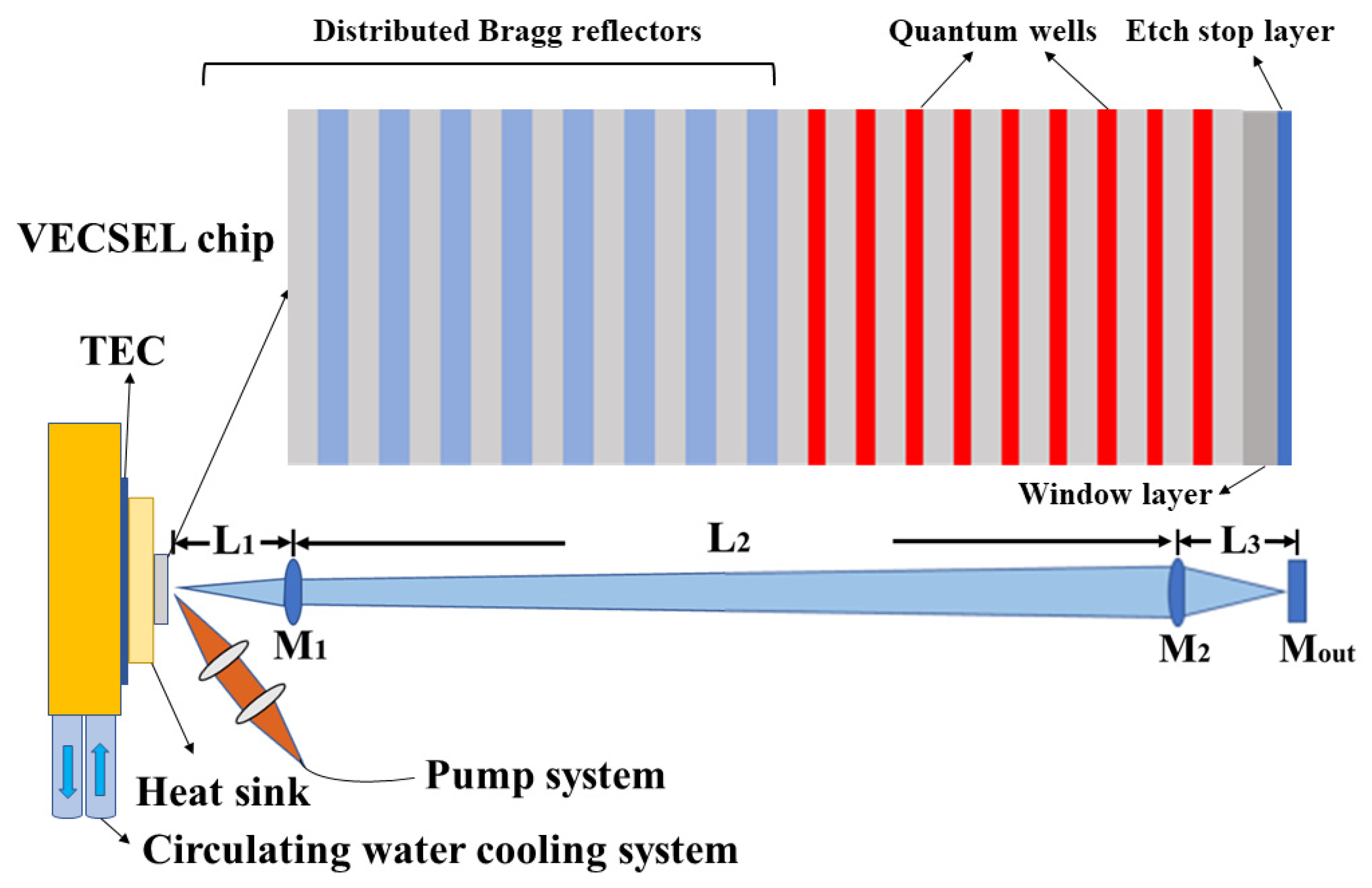
Figure 1 shows the wireless optical power transmission scheme based on a VECSEL external cavity structure. The long and straight cavity of the overall system consists of two parts. The transmitter end comprises a gain chip and a convex lens M1 with a curvature radius of 15 cm. The output end comprises a plane mirror Mout and a concave lens M2 with a curvature radius of 15 cm. The distance L2 between the two ends is the energy transmission distance. M1 adjusts the divergence angle of the output light in the cavity such that the beam in the cavity does not exceed the size of M2 when transmitted to the output end. M2 and Mout form the structure of the retroreflective mirror, which can reflect the incident light back to the original path. The plane mirror Mout has a reflectance of 97.5% in the 980-nm band. M1 and M2 have the same specifications, and a convex lens with a transmittance of >99.9% at 980 nm is selected to reduce the loss caused by lens reflection in the cavity. By adjusting the parameters of the laser cavity, stable laser oscillation can be maintained even if the distance L2 between the emitter and output is increased to several meters.
Figure 1 shows the pump and heat dissipation systems. The pump system consists of a pump source and a focusing mirror group. The pump source provides an 808-nm pump-light output with a maximum pump power of 100 W. The output of the pump source is focused on the chip surface at an angle of 45° using a focusing mirror group that comprises two convex lenses. By adjusting the angle between the reflector group and chip, the size of the pump spot on the chip surface can be controlled. The heat dissipation system consists of a thermoelectric cooler (TEC) and circulating water cooling system. As shown in Figure 1, TEC is inserted between the copper radiator and base. TEC controls the temperature of the copper radiator, circulating water through the copper base to remove the heat generated via TEC refrigeration.
The gain chip is grown on GaAs (100) substrates using an Aixtron 200/4 MOCVD system. The etch-stop layer, window layer, active region, and distributed Bragg reflector (DBR) are successively grown on the GaAs substrate. After the structure growth is completed, the wafer is cleaved into a 3 mm × 3 mm chip. At this time, the bottom of the chip is the substrate, and the outermost layer is DBR, which is referred to as a bottom-emitting structure [40]. DBR is metallized and then soldered onto the copper heat sink using indium. The waste heat generated by the chip is rapidly dissipated through the copper radiator. A portion of the GaAs substrate is then removed by mechanical thinning, and all remaining substrates are subsequently removed by chemical etching. The GaAsP etch-stop layer is used to protect the chip structure from chemical etching. After removing the substrate, the copper heat sink is installed on the heat dissipation system.
As shown in the structural illustration of Figure 1, the Bragg reflector consists of 30 pairs of AlAs/GaAs pairs with a quarter-wavelength thickness that are designed to provide 99.9% reflectivity centered at 980 nm. The adjacent active region comprises nine 7-nm-thick InGaAs quantum wells, each of which is separated by a GaAs pump-light absorber layer. Thin GaAsP layers on both sides of QWs are used to compensate for the material strain produced by InGaAs QWs [41]. Finally, a 30-nm-thick AlGaAs window layer and a thin GaAsP etch-stop layer are grown. The role of the AlGaAs window layer is to prevent excited state carriers from escaping to the surface and performing non-radiative recombination [42].
The laser cavity scheme in Figure 1 is used to achieve long-distance stable laser oscillations and requires accurate dimensions. The distance between M1 and the chip is L1, and the distance between M2 and M1 is L2, which is the energy transmission distance. M1 is used to adjust the beam size in the cavity to reduce the beam divergence angle, and the beam size does not exceed the lens size when reaching the M2 surface. M2 focuses the intracavity beam on Mout, and the light reflected by Mout converges on the chip surface through M2 and M1. Owing to the long cavity length, small changes in the lens position in the laser cavity will have a strong impact on the stability of the laser cavity. Therefore, we establish a theoretical model to simulate the stability of the laser cavity using the generalized ABCD matrix algorithm to obtain a more accurate laser cavity design scheme [43]. Owing to the simplicity and efficiency of the ABCD matrix when considering beam propagation, this method has been widely used to design laser resonators and analyze beam propagation [44].
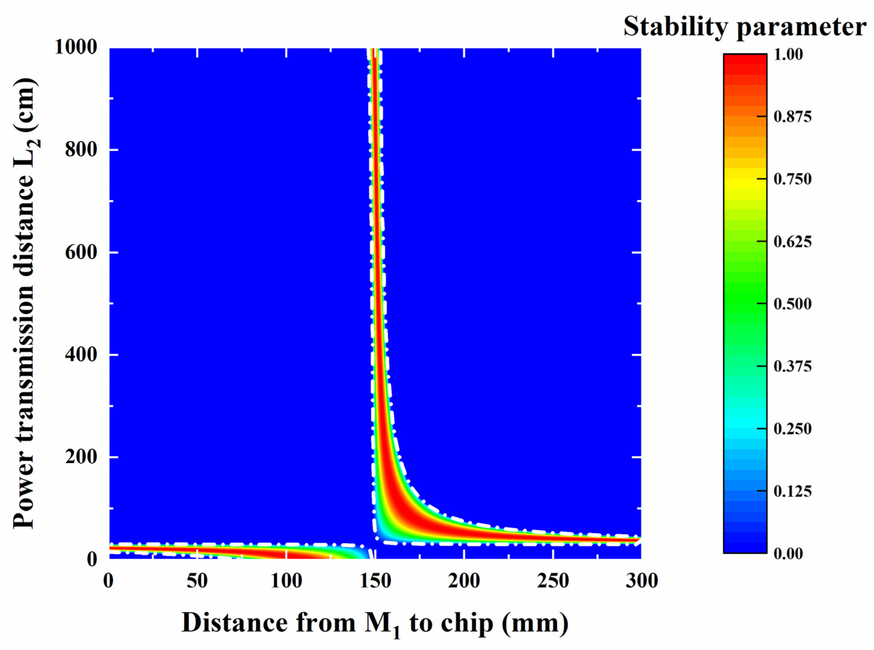
Each lens in the laser cavity will affect the beam transmission inside of the cavity, and it is therefore necessary to calculate the ABCD matrix transformation after the beam matrix in the cavity passes through each lens. When a laser beam can oscillate multiple times without leakage, a stable laser cavity is achieved. Therefore, according to the stability conditions of the coaxial spherical cavity, the absolute value of the range of stability parameters calculated using the ABCD matrix is between 0 and 1 [45]. Figure 2 shows the stable working area of the laser cavity, where the unstable working area of the laser cavity is indicated in dark blue.
In the graph shown in Figure 2, the abscissa is the distance L1 from M1 to the chip, and the ordinate is the energy transmission distance L2. It can be seen that the laser cavity can stably function within 10 m of the transmission distance L2 when L1 is 155 mm. Therefore, this cavity type can indeed achieve long-distance energy transmission. Although the simulation results show that the cavity is stable, it does not necessarily achieve a high power output. The beam size on the chip surface has a large influence on the output performance of VECSEL. The beam radius of the intracavity oscillating beam on the chip surface is therefore investigated via simulation.
Figure 3 shows the variation of the intracavity beam radius on the chip surface with the cavity length L2. As the energy transmission distance L2 increases, the beam radius on the chip surface becomes smaller. When the transmission distance L2 is equal to 100 cm, the beam radius on the chip surface is approximately 50 μm. As L2 continues to increase, the beam radius on the chip surface gradually decreases and finally stabilizes at approximately 35 μm. The beam size on the chip surface matches the pump spot, and the optically pumped laser can achieve the best output under these conditions [46]. A large pump spot represents an increased output, and the pump spot size has a maximum critical value. Once the critical value is exceeded, the thermal resistance of the radiator will be greater than the thermal resistance of the chip, and the radiator will no longer function properly. According to the critical value formula, the pump spot size that the copper heat sink can support is approximately 200 μm [46]. The 35-μm intracavity beam radius on the chip surface therefore cannot support such a large pump spot size, and the laser cavity must be adjusted.
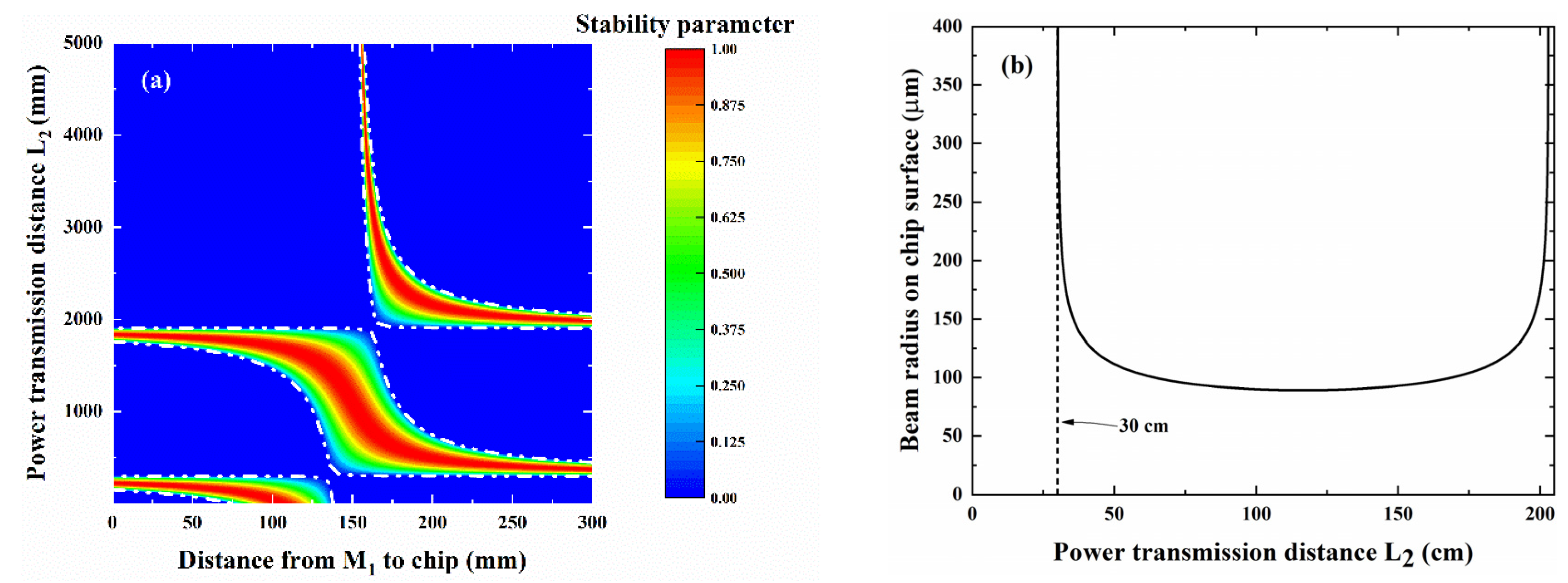
Figure 4 shows the simulation results obtained after adjusting the position of the optical device in the laser cavity. As shown in Figure 4a, the stable operating region of the laser cavity after the parameter adjustment has changed significantly. Compared with the original stable cavity region, the laser cavity can also function stably at a transmission distance L2 of 5 m. When L2 is in the range of 0.3 to 2 m, the stable working range of the laser cavity is widened and the distance L1 between the chip and M1 ranges from 15 to 16 cm. This relatively wide stability range indicates that the difficulty associated with laser cavity debugging is reduced. Next, the variation of the beam radius of the chip surface with the transmission distance L2 is next simulated in this stable working range. As shown in Figure 4b, when the transmission distance is within 0.3 to 2 m, the beam radius of the intracavity beam on the chip surface remains above 100 μm. Beyond the stable working area, the beam radius on the chip surface becomes extremely large, which indicates the leakage of the laser in the cavity. A cavity base film with this spot size is sufficient to support a large pump spot and achieve a high power output.
Figure 5 shows the radius variations of the beam propagation over the entire cavity when L2 is 50, 100, and 150 cm. The position of M1 is indicated in this figure, and the output and transmitter are framed by the black dashed lines. As the propagation distance L2 increases, the beam radius in the range of the transmitting end does not significantly change, indicating that a compact transmitting end can be achieved. The increase in the propagation distance L2 leads to a slight increase in the beam radius on the surface of M2. The output end composed of M2 and the plane mirror can completely receive and reflect all incident light, return the light to the transmitting end, and form a stable laser oscillation. Therefore, the large beam size incident on the M2 surface can make the output end slightly deviate from the main optical axis such that the output end alignment is easier to achieve. The beam size in the output end is extremely stable and maintains the same trend. The beam radius on the output mirror is approximately 50 μm. When the transmission distance L2 increases from 50 to 150 cm, the surface beam radius of the chip surface and output mirror remain stable. The wireless charging system can therefore maintain a stable working state over a constantly changing transmission distance.

3. Experimental Results

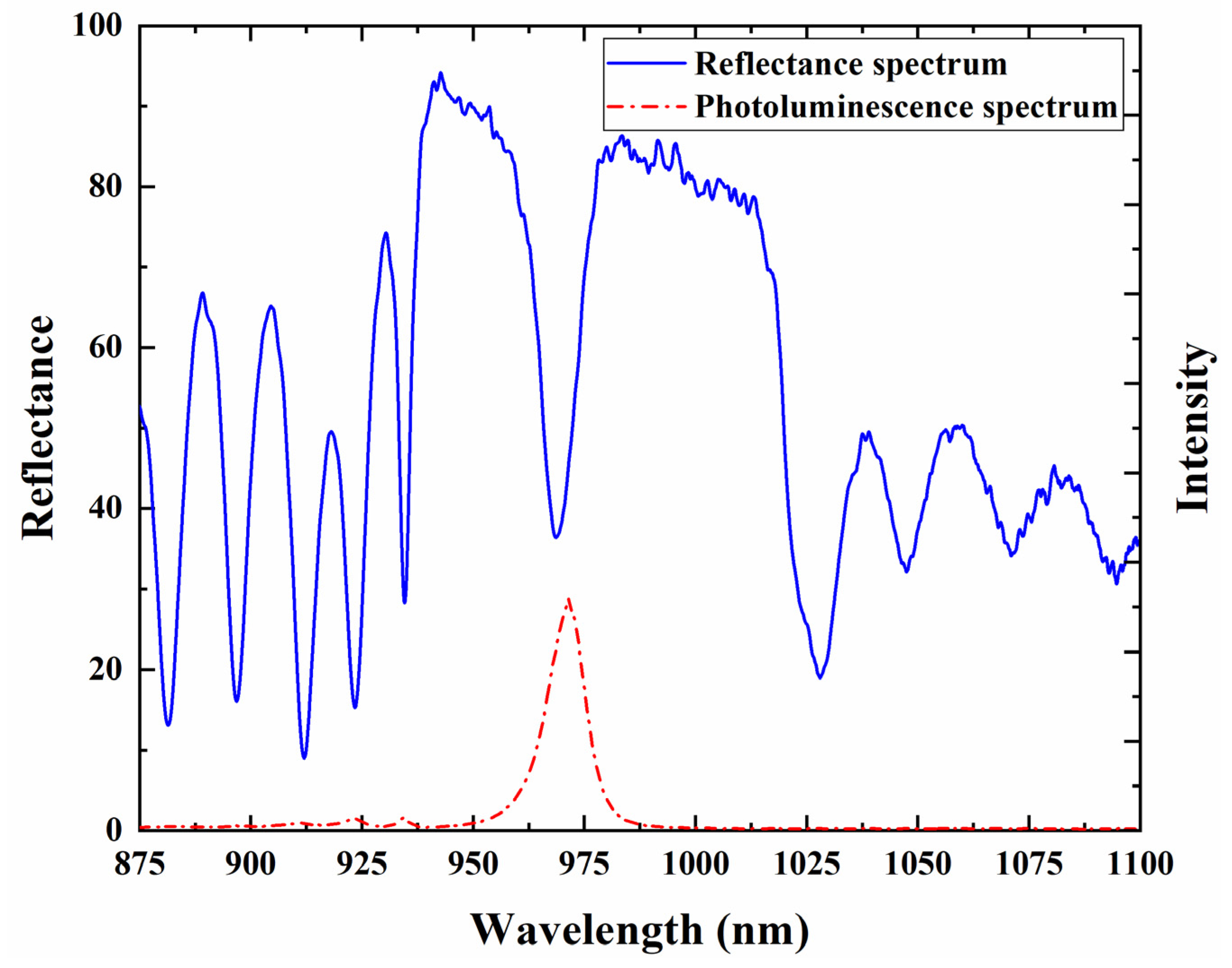
We determined the optimal parameters of the experimental system via simulation and designed a straight cavity that can operate stably over a long cavity length, as shown in Figure 1. Before building the straight cavity, the reflection spectrum and photoluminescence (PL) spectrum of the chip were tested. Figure 6 shows the PL and reflection spectra of the gain chip after removing the GaAs substrate. The reflection spectrum has a wide reflection band of 80 nm, extending from 940 to 1020 nm. The reflectivity decreases at 969 nm, which represents the resonance wavelength position of the Fabry–Perot (F–P) cavity [47]. The peak of the PL spectrum as modified by the microcavity is 971 nm. No side peak in the PL spectrum is present, which indicates that the chip material after strain compensation grows uniformly without serious growth defects.
Figure 7 shows the functional relationship between the output and pump powers at different transmission distances L2 (50, 100, and 150 cm) at a TEC control temperature of 0 °C. The output power increases linearly as the pump power is increased until thermal inversion occurs. The process of thermal inversion occurs because the pump power is too high such that the radiator cannot remove the waste heat generated by the active region at an adequate rate, and the temperature of the active region is therefore too high. The temperature drift coefficients of the cavity mode and gain peak differ [40]. Excessive temperatures lead to a large mismatch between the gain peak and cavity mode, resulting in a decrease in the output power. The slope efficiencies of the power curves do not significantly vary between different transmission distances, which indicates that the loss caused by the increase in the cavity length is small, as indicated by the variation of the peak power with the cavity length. The peak power is 1.781, 1.734, and 1.666 W at transmission distances of 50, 100, and 150 cm, respectively. When the transmission distance L2 increases from 50 to 100 cm, the peak power decreases by 2.6%. As the transmission distance L2 increases from 100 to 150 cm, the peak power decreases by only 3.9%. Such a small power attenuation of 6.4%/m is sufficient to prove that this cavity can support long-distance power transmission through parameter optimization.
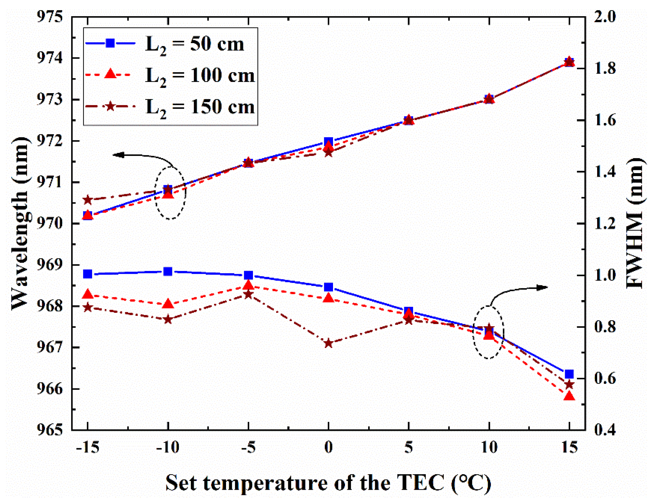
Figure 8 shows the variation of the output wavelength and full width at half maximum (FWHM) values of VECSEL with the temperature at different transmission distances. The pump power, angle, and spot size of VECSELs with different transmission distances remain unchanged. At the same temperature, there is little change in the output wavelength as the transmission distance increases. As the temperature controlled by TEC increases, the output wavelengths of different transmission distances maintain the same growth trend. As the temperature controlled by TEC is increased from −15 to 15 ℃, the output wavelength shifts from 970.18 (970.57 nm at 150 cm) to 973.9 nm. The variation of the wavelength with temperature is consistent, and the temperature drift coefficient is approximately 0.12 nm/°C, which indicates that the variation of the cavity length has little effect on the output wavelength. The FWHM values of different transmission distances are <1 nm at all temperatures. A longer transmission distance L2 is shown to result in a smaller FWHM. An increase in the cavity length leads to an increase in the cavity loss, suppression of the weaker cavity mode, and decrease in FWHM of the output wavelength. As a long cavity has an improved filtering effect on the mode with a lower intensity, a long cavity can be used to achieve a lower FWHM value.
Figure 9 shows the far-field modes of VECSEL at 0 °C at transmission distances L2 of 50, 100, and 150 cm. The far-field modes at different positions show Gaussian cross-sections in both dimensions. The insets show the 2D beam profiles captured by a charge coupled device (CCD). With an increase in the transmission distance L2, the distribution of the light beam profile remains uniformly circular. The divergence angles are 3.033°, 4.866°, and 4.095° at transmission distances L2 of 50, 100, and 150 cm, respectively. The divergence angles of the different transmission distances are less than 5°. This shows that the output performance of VECSELs can remain stable even if the transmission distance becomes larger.
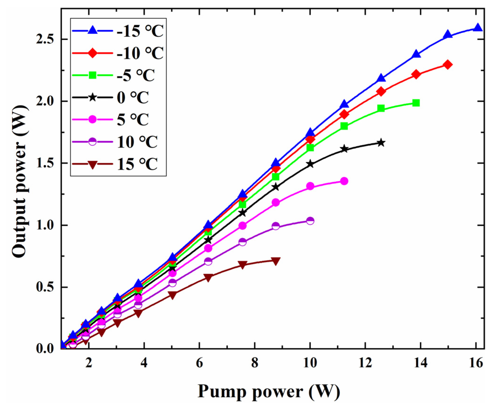
Figure 10 shows the influence of the radiator temperature on the VECSEL power curve when the transmission distance L2 is 150 cm. The power curves obtained at different temperatures exhibit the same trend, with an obvious linear growth region and thermal inversion. As the radiator temperature increases, the slope efficiency of the power curve decreases. This occurs because the loss caused by the absorption of free carriers in the semiconductor laser increases as the temperature increases. Consequently, the number of carriers overflowing from the active region increases, resulting in a decrease in the external differential quantum efficiency. At a transmission distance of 150 cm, we achieved a maximum output power of 2.589 W at a radiator temperature of −15 ℃.

4. Conclusions

We designed a safe and efficient wireless laser energy transmission scheme based on the unique external cavity structure of VECSEL. The stable oscillation of the laser cavity was determined using the ABCD transfer matrix, and a stable laser cavity with a theoretical distance of 10 m was designed. To achieve a high power output and simplify the debugging process, the laser cavity parameters were adjusted to achieve a wide stable region in the laser cavity with a transmission distance of 0.3 to 2 m. The size of the fundamental mode spot on the surface of the adjusted laser cavity chip was increased to support a large pump spot and achieve a high power output. This wireless power transfer scheme yielded an output of 2.589 W at a transmission distance of 150 cm. The influence of the variation of the transmission distance L2 on the output power was investigated, and a power reduction of approximately 6.4%/m was achieved. The beam profile of three transmission distances showed a Gaussian distribution, and the divergence angle was less than 5°.
In addition to being low cost, the optically pumped external cavity surface-emitting semiconductor laser has a small volume, high beam quality, and high output power. When an obstacle enters the laser cavity, the laser oscillation will immediately stop without causing damage. The proposed wireless energy transmission scheme based on a VECSEL laser cavity is safe and efficient and is ideal for indoor wireless charging applications. However, the current wireless energy transmission system is not modular and can only transmit energy along a straight line. In the future, we will focus on designing a small and compact modular laser system that can safely and efficiently transmit energy to multiple devices while deviating from the optical axis, providing a new strategy for enhancing the current wireless charging scheme.

Author Contributions

Project supervision, Y.N., L.W. and J.Z.; chip design, J.Z., X.Z. and C.C.; external cavity design, Z.Z. and Y.Z.; reflection spectrum measurement, Z.Z. and Y.G.; external cavity debugging, Z.Z., Y.G. and H.W.; comprehensive system performance test, Z.Z., Y.G. and Y.C.; analysis and discussion of experimental results, Z.Z., J.Z., C.C. and Y.Z.; writing—first draft preparation, Z.Z.; writing review and editing, J.Z.; fund Acquisition, J.Z., Y.N., L.Q. and L.W. All authors have read and agreed to the published version of the manuscript.

Funding

This work was funded by the National Key Research and Development Program of China (Grant no. 2018YFB2201103); the Major Program of National Natural Science Foundation of China (Grant no. 62090060); the Key Scientific and Technological Research Projects in Jilin Province (Grant no. 20220201066GX); and the National Natural Science Foundation of China (Grant nos. 61874119, 62274165, and 52172165).

Institutional Review Board Statement

Not applicable.

Informed Consent Statement

Not applicable.

Data Availability Statement

Experimental data are available upon reasonable request to the authors.

Conflicts of Interest

The authors declare no conflict of interest.

References

  1. Sodhro, A.H.; Awad, A.I.; van de Beek, J.; Nikolakopoulos, G. Intelligent authentication of 5G healthcare devices: A survey. Internet Things 2022, 20, 100610. [Google Scholar] [CrossRef]
  2. Singh, P.; Elmi, Z.; Meriga, V.K.; Pasha, J.; Dulebenets, M.A. Internet of Things for sustainable railway transportation: Past, present, and future. Clean. Logist. Supply Chain. 2022, 4, 100065. [Google Scholar] [CrossRef]
  3. Singh, P.; Elmi, Z.; Lau, Y.; Borowska-Stefańska, M.; Wiśniewski, S.; Dulebenets, M.A. Blockchain and AI Technology Convergence: Applications in Transportation Systems. Veh. Commun. 2022, 38, 100521. [Google Scholar] [CrossRef]
  4. Goswami, H.; Choudhury, H. Remote Registration and Group Authentication of IoT Devices in 5G Cellular Network. Comput. Secur. 2022, 120, 102806. [Google Scholar] [CrossRef]
  5. Singh, P.; Dulebenets, M.A.; Pasha, J.; Gonzalez, E.D.S.; Lau, Y.Y.; Kampmann, R. Deployment of autonomous trains in rail transportation: Current trends and existing challenges. IEEE Access 2021, 9, 91427–91461. [Google Scholar] [CrossRef]
  6. Delgado-Santos, P.; Stragapede, G.; Tolosana, R.; Guest, R.; Deravi, F.; Vera-Rodriguez, R. A survey of privacy vulnerabilities of mobile device sensors. ACM Comput. Surv. (CSUR) 2022, 54, 1–30. [Google Scholar] [CrossRef]
  7. Lu, F.; Zhang, H.; Mi, C. A review on the recent development of capacitive wireless power transfer technology. Energies 2017, 10, 1752. [Google Scholar] [CrossRef] [Green Version]
  8. Rim, C.T.; Mi, C. Wireless Power Transfer for Electric Vehicles and Mobile Devices; John Wiley & Sons: Hoboken, NJ, USA, 2017. [Google Scholar]
  9. Sun, L.; Ma, D.; Tang, H. A review of recent trends in wireless power transfer technology and its applications in electric vehicle wireless charging. Renew. Sustain. Energy Rev. 2018, 91, 490–503. [Google Scholar] [CrossRef]
  10. Zhang, S.; Qian, Z.; Wu, J.; Kong, F.; Lu, S. Wireless charger placement and power allocation for maximizing charging quality. IEEE Trans. Mob. Comput. 2017, 17, 1483–1496. [Google Scholar] [CrossRef]
  11. Hui, S.Y. Planar wireless charging technology for portable electronic products and Qi. Proc. IEEE 2013, 101, 1290–1301. [Google Scholar] [CrossRef]
  12. Xie, L.; Shi, Y.; Hou, Y.T.; Lou, A. Wireless power transfer and applications to sensor networks. IEEE Wirel. Commun. 2013, 20, 140–145. [Google Scholar]
  13. Costanzo, A.; Dionigi, M.; Masotti, D.; Mongiardo, M.; Monti, G.; Tarricone, L.; Sorrentino, R. Electromagnetic energy harvesting and wireless power transmission: A unified approach. Proc. IEEE 2014, 102, 1692–1711. [Google Scholar] [CrossRef]
  14. Wei, X.; Wang, Z.; Dai, H. A critical review of wireless power transfer via strongly coupled magnetic resonances. Energies 2014, 7, 4316–4341. [Google Scholar] [CrossRef] [Green Version]
  15. Pantic, Z.; Lukic, S.M. Framework and topology for active tuning of parallel compensated receivers in power transfer systems. IEEE Trans. Power Electron. 2012, 27, 4503–4513. [Google Scholar] [CrossRef]
  16. Kurs, A.; Moffatt, R.; Soljačić, M. Simultaneous midrange power transfer to multiple devices. Appl. Phys. Lett. 2010, 96, 044102. [Google Scholar] [CrossRef]
  17. Karalis, A.; Joannopoulos, J.D.; Soljačić, M. Efficient wireless non-radiative midrange energy transfer. Ann. Phys. 2008, 323, 34–48. [Google Scholar] [CrossRef] [Green Version]
  18. Fu, W.; Zhang, B.; Qiu, D. Study on frequency-tracking wireless power transfer system by resonant coupling. In Proceedings of the 2009 IEEE 6th International Power Electronics and Motion Control Conference, Wuhan, China, 17–20 May 2009; IEEE Publications: Piscataway, NJ, USA, 2009; Volume 2009, pp. 2658–2663. [Google Scholar] [CrossRef]
  19. Garnica, J.; Chinga, R.A.; Lin, J. Wireless power transmission: From far field to near field. Proc. IEEE 2013, 101, 1321–1331. [Google Scholar] [CrossRef]
  20. Huang, K.; Lau, V.K.N. Enabling wireless power transfer in cellular networks: Architecture, modeling and deployment. IEEE Trans. Wirel. Commun. 2014, 13, 902–912. [Google Scholar] [CrossRef] [Green Version]
  21. Ladan, S.; Ghassemi, N.; Ghiotto, A.; Wu, K. Highly efficient compact rectenna for wireless energy harvesting application. IEEE Microw. Mag. 2013, 14, 117–122. [Google Scholar] [CrossRef]
  22. Summerer, L.; Purcell, O. Concepts for Wireless Energy Transmission via Laser; Europeans Space Agency (ESA)-Advanced Concepts Team: Noordwijk, The Netherlands, 2009. [Google Scholar]
  23. Man, Z.; Bao, J.; Xu, Z.; Lv, Z.; Liao, Q.; Yao, J.; Fu, H. Boosting the Efficiency of Organic Solid-State Lasers by Solvato-Tailored Assemblies. Adv. Funct. Mater. 2022, 2207282. [Google Scholar] [CrossRef]
  24. Kim, S.M.; Kim, S.M. Wireless optical energy transmission using optical beamforming. Opt. Eng. 2013, 52, 043205. [Google Scholar] [CrossRef]
  25. Putra, A.W.S.; Tanizawa, M.; Maruyama, T. Optical wireless power transmission using Si photovoltaic through air, water, and skin. IEEE Photonics Technol. Lett. 2018, 31, 157–160. [Google Scholar] [CrossRef]
  26. Ding, J.; Liu, W.; I, C.L.; Zhang, H.; Mei, H. Advanced progress of optical wireless technologies for power industry: An overview. Appl. Sci. 2020, 10, 6463. [Google Scholar] [CrossRef]
  27. Jin, K.; Zhou, W. Wireless laser power transmission: A review of recent progress. IEEE Trans. Power Electron. 2018, 34, 3842–3859. [Google Scholar] [CrossRef]
  28. Mukherjee, J.; Jarvis, S.; Perren, M.; Sweeney, S.J. Efficiency limits of laser power converters for optical power transfer applications. J. Phys. D Appl. Phys. 2013, 46, 264006. [Google Scholar] [CrossRef]
  29. Guina, M.; Rantamäki, A.; Härkönen, A. Optically pumped VECSELs: Review of technology and progress. J. Phys. D Appl. Phys. 2017, 50, 383001. [Google Scholar] [CrossRef]
  30. Kuznetsov, M. VECSEL Semiconductor Lasers: A Path to High-Power, Quality Beam and UV to IR Wavelength by Design; Wiley Online Library: Hoboken, NJ, USA, 2010. [Google Scholar]
  31. Tropper, A.C.; Foreman, H.D.; Garnache, A.; Wilcox, K.G.; Hoogland, S.H. Vertical-external-cavity semiconductor lasers. J. Phys. D Appl. Phys. 2004, 37, R75–R85. [Google Scholar] [CrossRef]
  32. Kantola, E.; Leinonen, T.; Ranta, S.; Tavast, M.; Guina, M. High-efficiency 20 W yellow VECSEL. Opt. Express 2014, 22, 6372–6380. [Google Scholar] [CrossRef]
  33. Tilma, B.W.; Mangold, M.; Zaugg, C.A.; Link, S.M.; Waldburger, D.; Klenner, A.; Mayer, A.S.; Gini, E.; Golling, M.; Keller, U. Recent advances in ultrafast semiconductor disk lasers. Light Sci. Appl. 2015, 4, e310. [Google Scholar] [CrossRef] [Green Version]
  34. Lorenser, D.; Maas, D.J.H.C.; Unold, H.J.; Bellancourt, A.-R.; Rudin, B.; Gini, E.; Ebling, D.; Keller, U. 50-GHz passively mode-locked surface-emitting semiconductor laser with 100-mW average output power. IEEE J. Quantum Electron. 2006, 42, 838–847. [Google Scholar] [CrossRef]
  35. Kemp, A.J.; Maclean, A.J.; Hastie, J.E.; Smith, S.A.; Hopkins, J.-M.; Calvez, S.; Valentine, G.J.; Dawson, M.D.; Burns, D. Thermal lensing, thermal management and transverse mode control in microchip VECSELs. Appl. Phys. B 2006, 83, 189–194. [Google Scholar] [CrossRef]
  36. Mansour, A.; Mesleh, R.; Abaza, M. New challenges in wireless and free space optical communications. Opt. Lasers Eng. 2017, 89, 95–108. [Google Scholar] [CrossRef]
  37. Mujeeb-U-Rahman, M.; Adalian, D.; Chang, C.F.; Scherer, A. Optical power transfer and communication methods for wireless implantable sensing platforms. J. Biomed. Opt. 2015, 20, 095012. [Google Scholar] [CrossRef] [PubMed] [Green Version]
  38. Minotto, A.; Haigh, P.A.; Łukasiewicz, Ł.G.; Lunedei, E.; Gryko, D.T.; Darwazeh, I.; Cacialli, F. Visible light communication with efficient farred/near-infrared polymer light-emitting diodes. Light Sci. Appl. 2020, 9, 70. [Google Scholar] [CrossRef] [PubMed] [Green Version]
  39. Tavakkolnia, I.; Jagadamma, L.K.; Bian, R.; Manousiadis, P.P.; Videv, S.; Turnbull, G.A.; Samuel, I.D.W.; Haas, H. Organic photovoltaics for simultaneous energy harvesting and high-speed MIMO optical wireless communications. Light Sci. Appl. 2021, 10, 41. [Google Scholar] [CrossRef] [PubMed]
  40. Tropper, A.C.; Hoogland, S. Extended cavity surface-emitting semiconductor lasers. Prog. Quantum Electron. 2006, 30, 1–43. [Google Scholar] [CrossRef]
  41. Jasik, A.; Sokół, A.K.; Broda, A.; Sankowska, I.; Wójcik-Jedlińska, A.; Wasiak, M.; Trajnerowicz, A.; Kubacka-Traczyk, J.; Muszalski, J. Impact of strain on periodic gain structures in vertical external cavity surface-emitting lasers. Appl. Phys. B 2016, 122, 258. [Google Scholar] [CrossRef] [Green Version]
  42. Holm, M.A.; Burns, D.; Ferguson, A.I.; Dawson, M.D. Actively stabilized single-frequency vertical-external-cavity AlGaAs laser. IEEE Photonics Technol. Lett. 1999, 11, 1551–1553. [Google Scholar] [CrossRef]
  43. Siegman, A.E. New developments in laser resonators. In Optical Resonators; SPIE: Bellingham, WA, USA, 1990; Volume 1224, pp. 2–14. [Google Scholar]
  44. Alda, J. Laser and Gaussian beam propagation and transformation. In Encyclopedia of Optical Engineering; CRC Press: Boca Raton, FL, USA, 2003; Volume 999. [Google Scholar]
  45. Tromborg, B.; Osmundsen, J.; Olesen, H. Stability analysis for a semiconductor laser in an external cavity. IEEE J. Quantum Electron. 1984, 20, 1023–1032. [Google Scholar] [CrossRef]
  46. Haring, R.; Paschotta, M.; Aschwanden, A.; Gini, E.; Morier-Genoud, F.; Keller, U. High-power passively mode-locked semiconductor lasers. IEEE J. Quantum Electron. 2002, 38, 1268–1275. [Google Scholar] [CrossRef]
  47. Yang, H.D.; Lu, C.; Hsiao, R.; Chiou, C.; Lee, C.; Huang, C.; Yu, H.; Wang, C.; Lin, K.; Maleev, N.A.; et al. Characteristics of MOCVD- and MBE-grown InGa(N)As VCSELs. Semicond. Sci. Technol. 2005, 20, 834–839. [Google Scholar] [CrossRef]
Figure 1. Schematic of the working principle in the long-cavity VECSEL.
Crystals 12 01475 g001
Figure 2. Influence of the cavity lengths L1 and L2 in VECSEL on the cavity stability. The area enclosed by the white dotted line is the working area for achieving a stable cavity.
Crystals 12 01475 g002
Figure 3. Beam radius of the cavity on the chip surface varying with the cavity length L2.
Crystals 12 01475 g003
Figure 4. Simulation results after redesigning the cavity parameters. (a) Influence of the cavity lengths L1 and L2 in the VECSEL on the cavity stability. The area enclosed by the white dotted line is the working area for cavity stabilization. (b) Beam radius of the cavity on the chip surface varying with the cavity length L2.
Crystals 12 01475 g004
Figure 5. VECSEL internal oscillating laser beam distribution for L4 values of 50, 100, and 150 cm.
Crystals 12 01475 g005
Figure 6. Gain chip reflection spectrum (solid line) and PL spectrum C (dashed red line) of the InGaAs chip obtained at 0°.
Crystals 12 01475 g006
Figure 7. VECSEL output power curves for different external cavity lengths at 0 °C.
Crystals 12 01475 g007
Figure 8. Output wavelength and FWHM of VECSEL varying with the temperature at different transmission distances.
Crystals 12 01475 g008
Figure 9. One-dimensional far-field modes of VECSEL measured at different transmission distances L2 of (a) 50, (b) 100, and (c) 150 cm. The beam profiles of VECSEL are shown in the inset images.
Crystals 12 01475 g009
Figure 10. VECSEL output power curve for a transmission distance L2 of 150 cm at different operating temperatures.
Crystals 12 01475 g010
Publisher’s Note: MDPI stays neutral with regard to jurisdictional claims in published maps and institutional affiliations.