Article

A Novel Structured Magnetic Field Sensor Based on Photonic Crystal Fiber Filled with Magnetic Fluid

Science and Information College, Qingdao Agricultural University, Qingdao 266109, China
*
Author to whom correspondence should be addressed.
Crystals 2022, 12(10), 1383; https://doi.org/10.3390/cryst12101383
Submission received: 2 September 2022 / Revised: 22 September 2022 / Accepted: 27 September 2022 / Published: 29 September 2022
(This article belongs to the Special Issue Photonic and Phononic Crystals)

Abstract

:
A novel structured magnetic field sensor based on dual-core photonic crystal fiber is proposed which has two elliptical central holes filled with magnetic fluid and some elliptical cladding air holes. The transmission characteristics of the dual-core photonic crystal fiber such as coupling length, birefringence, and coupling loss are analyzed with changing structural parameters. Enhanced birefringence is obtained by the novel structure of two elliptical central holes and some elliptical cladding air holes. The sensitivity of the magnetic sensor is calculated, and the numerical simulation result shows that the highest sensitivity of 1200 pm/Oe can be achieved.

1. Introduction

Photonic crystals are artificial microstructures composed of different refractive index media arranged periodically which are characterized by photonic band gap. According to the different spatial configurations of the media composed of photonic crystals, they can be divided into one-dimensional, two-dimensional, and three-dimensional photonic crystals. The one-dimensional photonic crystals can be used for various photonic and electronic applications, such as superconducting photonic crystals [1,2,3,4,5,6,7], water desalination [8], gas sensor [9], bio-photonic sensors [10,11], superconducting resonators [12], optical resonators [13], photonic crystals incorporated with nanocomposite materials [14], and PZT-5H background photonic crystals [15].
Photonic crystal fiber (PCF) is a two-dimensional photonic crystal. Compared with traditional optical fibers, it possesses many unique optical transmission properties, such as endlessly single-mode transmission, low confinement loss, high birefringence, high flexible design structures [16,17,18,19,20], etc. Because of these characteristics, PCF has been widely used in optical communications, optical devices, medical instruments, fiber sensors [21,22,23], etc. PCF is composed by solid substrate and a periodic array of microscopic air holes. Different sensitive materials can be easily filled in some air holes of PCF, including solids, liquids or gaseous substances, such as gold-filled or metal wire-filled [24,25], Ti-filled [26], liquid crystal-filled [27], benzene and chloroform liquid-filled [28], fluorine-doped, liquid ethanol-filled [29], etc. We can improve the characteristics of PCF by filling various sensitive materials into the air holes, such as high extinction ratio, polarization-dependent, shorter coupling length, ultrabroad bandwidth, tunable electro-optical modulator, etc. Due to its simple structure, small package dimensions, strong anti-interference ability, and high sensitivity, PCF sensors are one of the most potential applications. Especially, refractive index sensors [30,31,32], temperature sensors [33], salinity detectors [34], bending sensors [35], strain sensors [36], gas sensors [37], glucose sensors [38,39], electric field sensors [40], and magnetic field senors [41] can be easily achieved.
Magnetic fluid, as a new functional material, is sensitive to magnetism. The magnetic field sensor can be constructed from a PCF filled with magnetic fluid, which has strong anti-electromagnetic interference capability and high sensitivity; they have begun to attract research interest. R. Gao et al. have presented a new method of using PCF combined with magnetic fluid to measure the magnetic field [41], the PCF they used consists of a solid core surrounded by five rings of air holes, and the air holes of the cladding layer in the PCF have been filled with magnetic fluid, and the resolution reaches 0.09 Oe. Jianhua Li et al. have proposed a novel and simple magnetic field sensing system. It is a regular triangular lattice arrangement of the air holes in the PCF. The two air holes of the PCF, next to the central air hole, are filled with magnetic fluids. The results show that the magnetic field sensor with 15 cm PCFs has a large sensing range and high sensitivity of 4.80 pm/Oe [42]. Rahul Kumar Gangwar et al. have reported a PCF magnetic field sensor with 1 cm length which has a large sensitivity of 305.8 pm/Oe [43]. There are two big air holes in the center of the PCF filled with magnetic fluid, and the cladding air holes are arranged in a hexagonal shape around the central large holes. Chen et al. designed a magnetic field sensor using a polarization-maintaining PCF that filled the magnetic fluid in the cladding layer of the fiber, with a high sensitivity of 542.9 pm/Oe [44]. Moutusi De et al. have designed a magnetic field sensor using a square lattice PCF, and sensitivity reached 799.07 pm/Oe [45]. Qiang Liu et al. have reported a PCF magnetic field sensor with two microholes which formed two defect cores [46]; the magnetic field was measured by measuring the drift of resonance wavelength, and the highest sensitivity was 948 pm/Oe when the external magnetic field was 50 Oe.
Different structures of PCF will obtain different performances. In this paper, we propose a novel structure magnetic field sensor that infiltrates magnetic fluid in the dual-core PCF. The PCF has a new structure with two elliptical cores filled with magnetic fluid and some elliptical cladding air holes in the cladding layer. Using the finite element method (FEM), we analyze the influence of the structural parameters and magnetic field on the refractive index, coupling length, birefringence, coupling loss, and output power of the fiber. The results of numerical simulation show that the magnetic sensor has high birefringence, and the magnetic sensitivity that can be achieved is 1200 pm/Oe.

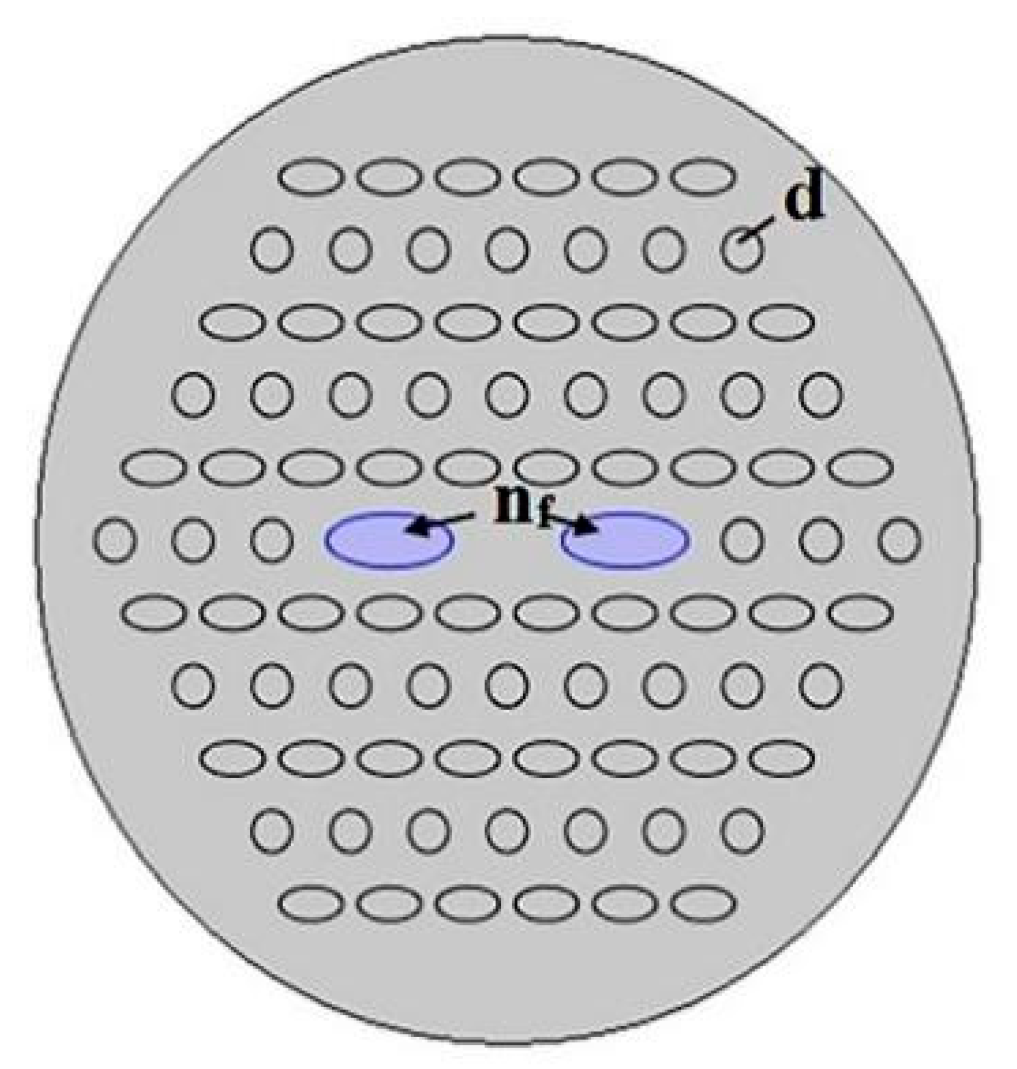
2. Structure and Principle

The cross-section of the dual-core PCF is shown in Figure 1. The air holes are arranged in a hexagonal lattice, the diameter of the circle holes of the cladding is d. In addition, other air holes in the cladding are elliptical holes whose minor axis diameter is b = 0.8 d, the ellipticity is η, and its refractive index is nair = 1.0. The distance between two air holes is Λ named pitch. The background material is silica, and its refractive index is nsi = 1.45. By employing sol–gel techniques, the suggested structure can be easily fabricated [9]. There are two big elliptical symmetrical holes in the center of the fiber, filled with magnetic fluids of Fe3O4. The minor axis diameter of the elliptical core is cd, the ellipticity is ηc, and the refractive index is nf.
The proposed magnetic field sensor can be realized experimentally [23,41]. As shown in Figure 2, the experimental setup of the magnetic field sensor consists of a broadband source (BBS), single-mode fiber (SMF), electromagnet, and optical spectrum analyzer (OSA). The BBS emits the broadband light to the SMF and then injects it into one fiber core of the PCF; light from the other fiber core of the PCF passes through the SMF, and the output spectral response of the PCF with a different magnetic field can be obtained by the OSA. Meanwhile, the magnetic field strength and the sensitivity can be measured. It is difficult to transmit light between SMF and PCF in experiments. Wang has achieved this by constructing tapered optical fibers [47].
Magnetic fluid (MF) is a gel-like liquid combined with Fe3O4 nanoparticles, surfactant, and base liquid. The presence of surfactant makes the magnetic fluid form a stable colloidal system. When the external magnetic field changes, it changes the distribution of the Fe3O4 nanoparticles which are the main components of magnetic fluid; meanwhile, the refractive index of the magnetic fluid changes. Magnetic fluid has magnetic reaction properties and the flow characteristics of liquid at the same time, making it easier to fill PCF. In the numerical calculation process, the effects of temperature and magnetism on the refractive index of silica can be ignored [29] for the reason that the thermo-optic coefficient of the magnetic fluid is much larger than that of silica, which is the background material of PCF. When the external magnetic field or temperature changes, the refractive index of magnetic fluid changes, which can be calculated by the Langevin function [48] shown as Equation (1).
n = n s n b coth α H H c , n T T α H H c , n + n b
where Hc,n is the critical magnetic field, ns is the saturated refractive index and nb is the initial refractive index of magnetic fluid, α is the fitting parameter, and T is the external temperature. In this paper, the corresponding parameters are nb = 1.4620, Hc,n = 30 Oe, ns = 1.4704, α = 3, and T = 300 K [48]. The magnetic field can be generated through an electromagnet; the strength of the applied field can be adjusted by the current of the electromagnet and monitored with a Gaussmeter. Since the refractive index of the silica background is smaller than that of the fiber cores which are filled with magnetic fluid, the light is transported in the two magnetic fluid-filled cores by a transport mechanism of total internal reflection. Using the injection–cure–cleave process will selectively infiltrate the core air holes of PCF with MF [49].
We can derive the electromagnetic wave equation of PCF from the Maxwell equations, shown in Equation (2) [16].
× 1 μ r × E = 2 π λ 2 ε r × E
where E denotes the electric field, μr and εr are the relative permittivity and relative magnetic permeability, and λ is the wavelength of light in a vacuum, respectively. The distribution of electric fields can be calculated by solving Equation (2).
According to the mode coupling theory, there are four fundamental supermodes in dual-core PCF, such as the x-even, y-even, x-odd, and y-odd modes. The electric field distributions of four fundamental supermodes are obtained through FEM numerical calculation, as shown in Figure 3.
We can treat the two cores of this PCF as independent waveguides according to the mode coupling theory, and the energy of the light emitted by BBS in the two cores is fully coupled. The coupling length of the dual-core fiber is defined as Equation (3) [50].
L x , y = λ 2 n e x , y n o x , y
where λ is the free space wavelength, nex and nox are the effective refractive indices of x-polarized even mode and odd mode, and ney and noy are the effective refractive indices of y-polarized even mode and odd mode.
Due to the asymmetric geometrical shape of the fiber, the refractive index difference of x and y in the orthogonal polarization direction increases, which greatly reduces the coupling between them, thus achieving high birefringence polarization-maintaining fiber. Birefringence can measure the performance of polarization-maintaining fiber. It is defined as the difference between the mode indices of the orthogonally polarized modes, and it can be calculated by Equation (4) [18].
B e , o = n e , o x n e , o y
The light is emitted by BBS launch at the A core of the PCF, then the optical power transfer from the A fiber core to the other B fiber core; after a length L along the PCF, the normalized output power of the B core can be represented as [51].
P x , y λ = s i n 2 n e x , y n o x , y π L λ
The total output power of the PCF must be the sum of two orthogonal x and y polarizations, which can be represented as Equation (6) [51].
P λ = 1 cos π λ n e x n o x + n e y n o y L · cos π λ n e x n o x + n e y n o y L
The variation of the external magnetic field causes the variation of the refractive index of the magnetic fluid that filled in the PCF; afterwards, the output spectrum shifts. The sensitivity of the magnetic sensor can be represented as Equation (7) [45].
S pm / Oe = Δ λ / Δ n
where Δλ is the wavelength shift of transmission curve and Δn is the change in magnetic field.

3. Results

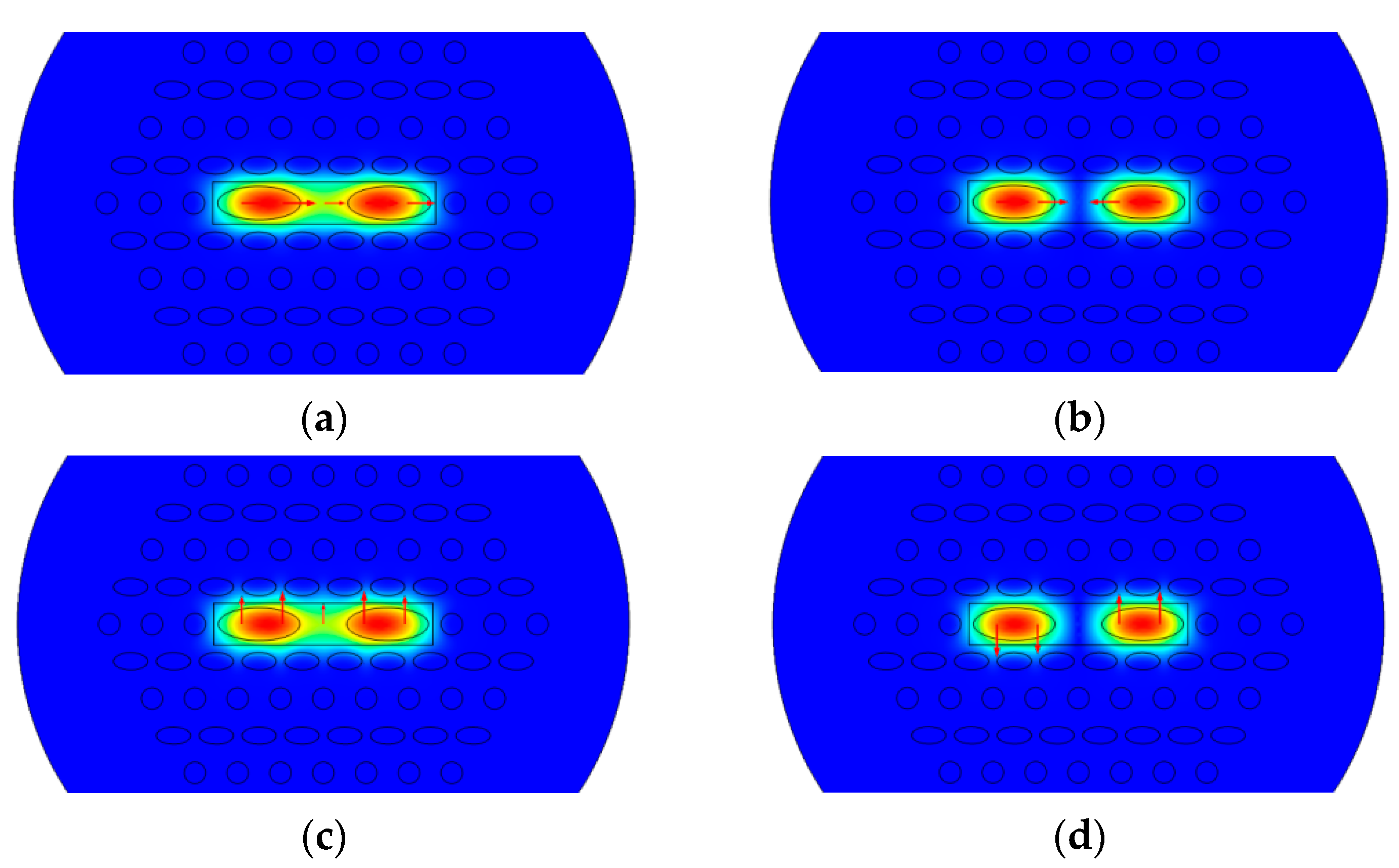
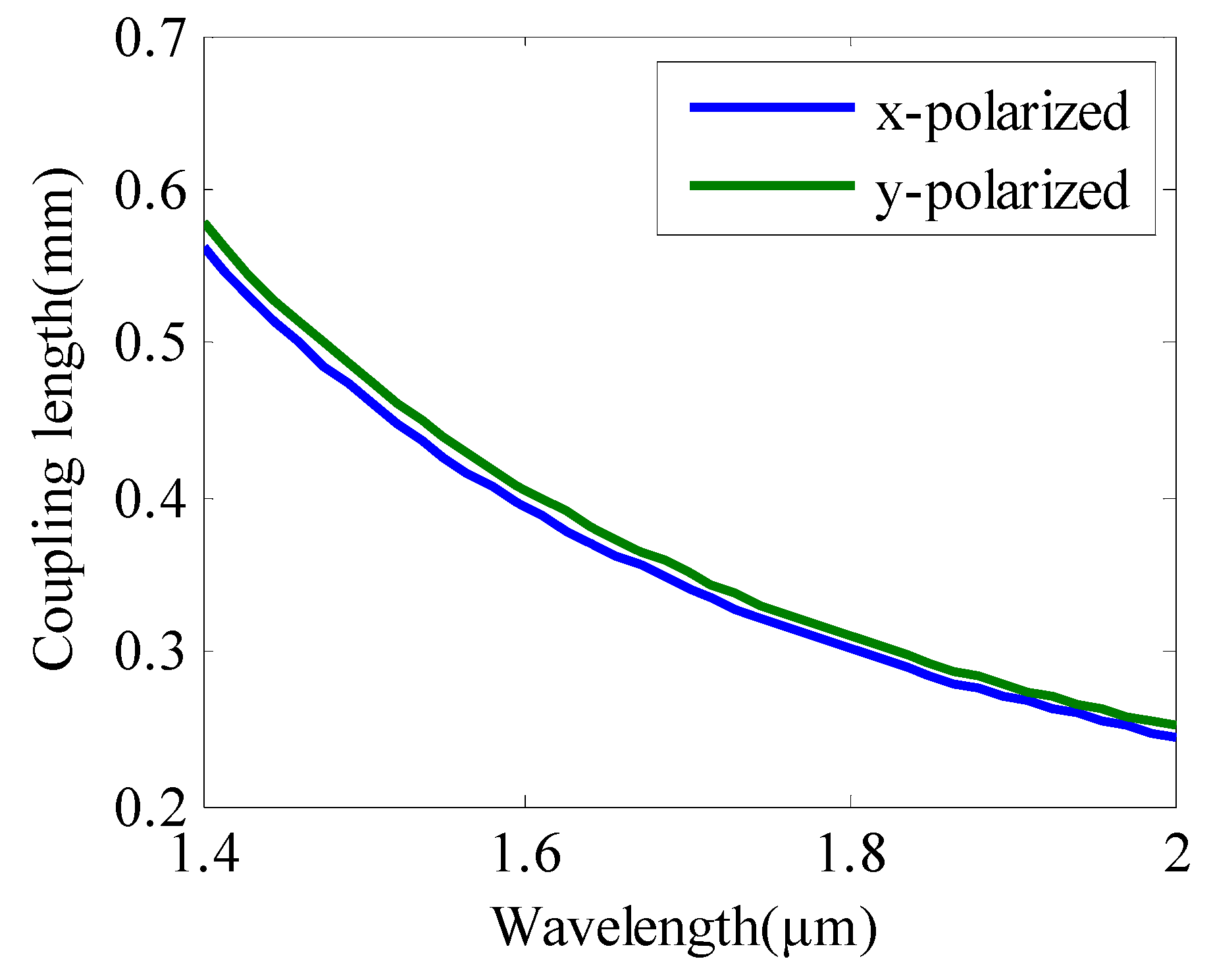
3.1. Coupling Lengths

Figure 4 shows the coupling length of our dual-core PCF, which is obtained by numerical calculation. When the magnetic field is 90 Oe, d is 0.84 μm, and Λ is 2.1 μm; the variation of coupling length with wavelength of the light is shown in Figure 4. When the diameter of the cladding air hole remains unchanged, the coupling length decreases, meanwhile, the wavelength of the light increases. The smaller the coupling length, the easier the coupling between two cores of the PCF. It is because the fiber cores have a descending light-binding ability. The coupling length of x-polarized mode is slightly lower than that of y-polarized mode. This is because the max axis of the central liquid-filled hole is in the x direction, which makes the coupling more difficult. The coupling lengths of x and y polarizations are almost the same, and the fiber can achieve good polarization-maintaining performance. The coupling length is fewer than 0.6 mm, indicating that the coupling of the two fiber cores is easier than the previous design [46].
Figure 5 shows the coupling length of x-polarized input light with varying structure parameters when the magnetic field is 90 Oe. Figure 5a shows the coupling length of different d for 0.84 μm, 1.05 μm, and 1.26 μm, and the coupling length decreases with the increase in d. Figure 5b shows the coupling length of different Λ for 2.1 μm, 2.3 μm, and 2.5 μm, and the coupling length increases with the increase in Λ. Figure 5c shows the coupling length of different ηc for 0.4, 0.6, and 0.8, and the coupling length decreases with the increase in ηc. Figure 5d shows the coupling length of different η for 0.4, 0.5, and 0.6, and the coupling length increases with the increase in η. The influence on coupling length of Λ and ηc is obviously greater than that of d and η because adjusting Λ and ηc can change the optical binding capacity of the core, and the coupling length will obviously change. From the result, we can see the coupling length of the PCF can be significantly adjusted by adjusting the distance between two air holes called Λ.

3.2. Birefringence Properties

High-birefringence PCF can be used as polarization-maintaining fiber, which can stabilize the polarization states of the guided light. The asymmetric structure of PCF can obtain greater birefringence. The birefringence is calculated by even mode of x- and y-polarized light. The numerical results of birefringence in this kind of dual-core PCF are shown in Figure 5. Because of the new structure of elliptical holes filling with magnetic fluid, the birefringence of this PCF is higher than the previous design [46]. The values of birefringence for all cases are greater than 10−3. The higher birefringence coefficient makes the fiber have stronger ability of maintaining polarization and reduces the coupling of the signals transmitted in the fiber communication system in the two polarization directions.
Figure 6 shows the birefringence of PCF with varying structure parameters when the magnetic field is 90 Oe. Figure 6a shows the birefringence of different d for 0.84 μm, 1.05 μm, and 1.26 μm, and the birefringence increases with the increase in d. Figure 6b shows the birefringence of different Λ for 2.1 μm, 2.3 μm, and 2.5 μm, and the birefringence decreases with the increase in Λ. Figure 6c shows the birefringence of different ηc for 0.4, 0.6, and 0.8, and the birefringence decreases with the increase in ηc. Figure 6d shows the birefringence of different η for 0.4, 0.5, and 0.6. The influence on the birefringence of d, Λ, and ηc is obviously greater than that of η because adjusting d, Λ, and ηc can enhance the asymmetry of the fiber. The difference between the propagation constants between the two axes of the fiber increases, so the birefringence increases. From the result, we can see the birefringence of the PCF can be significantly adjusted by adjusting the d or the distance between two air holes Λ.

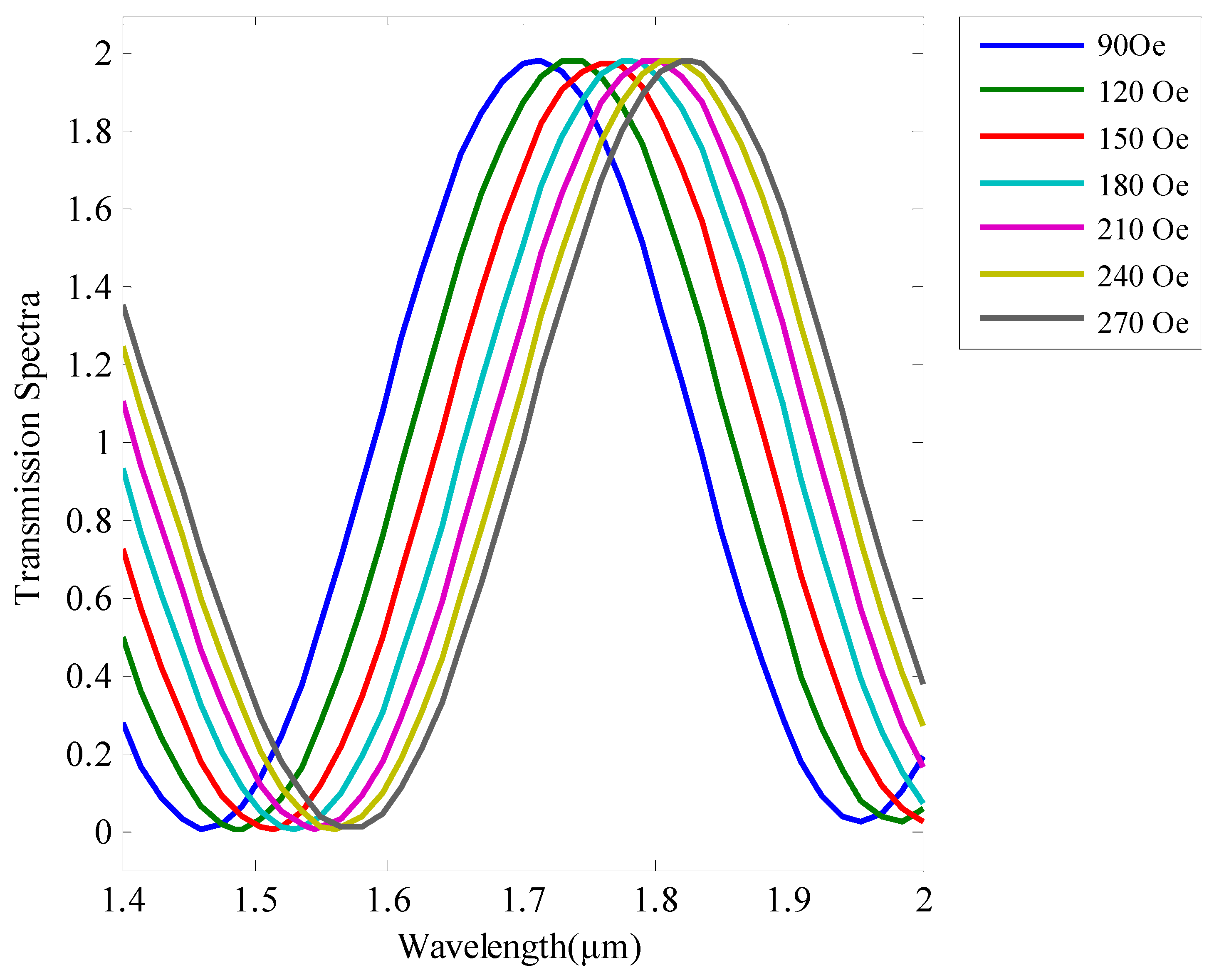
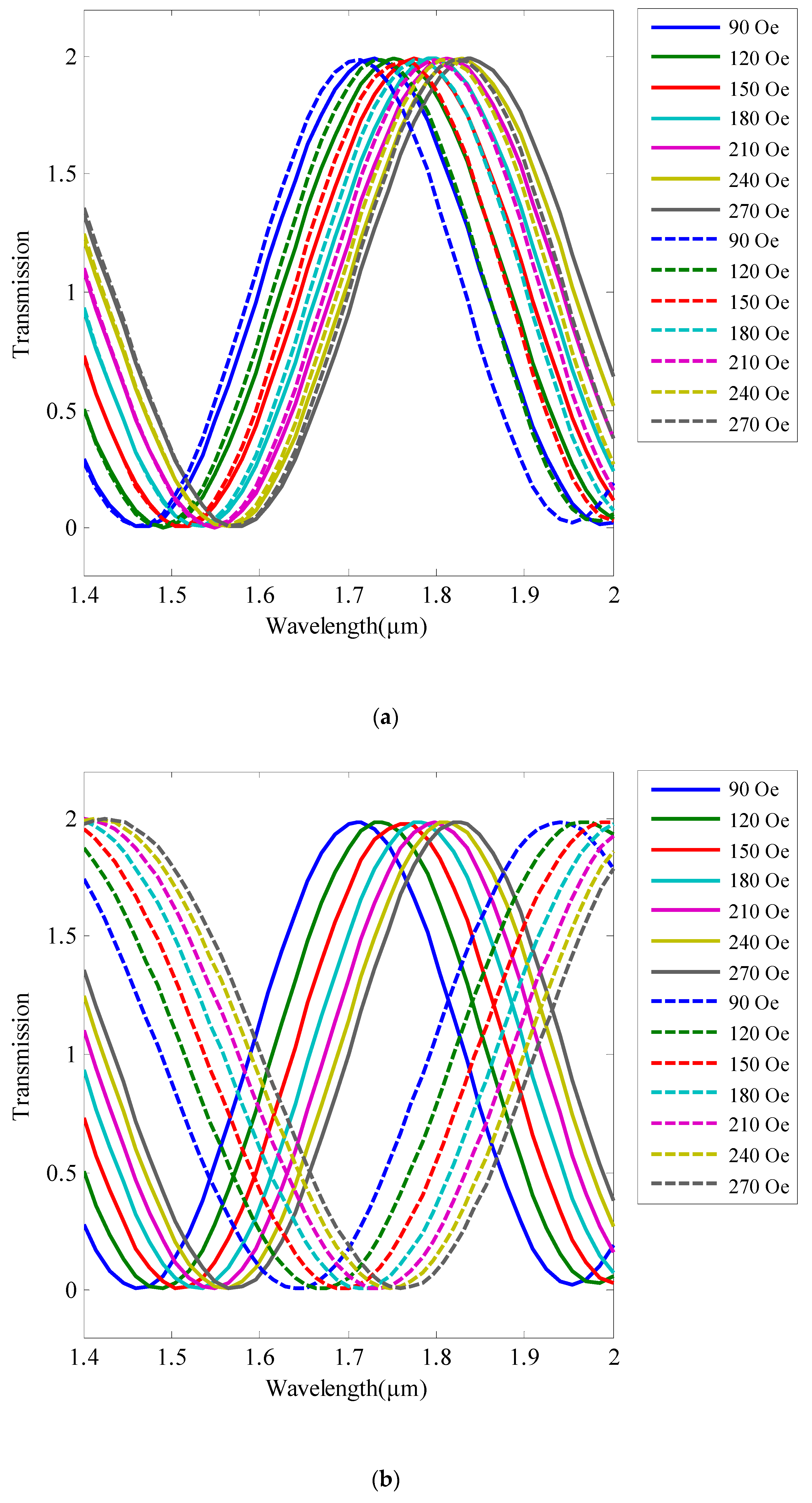
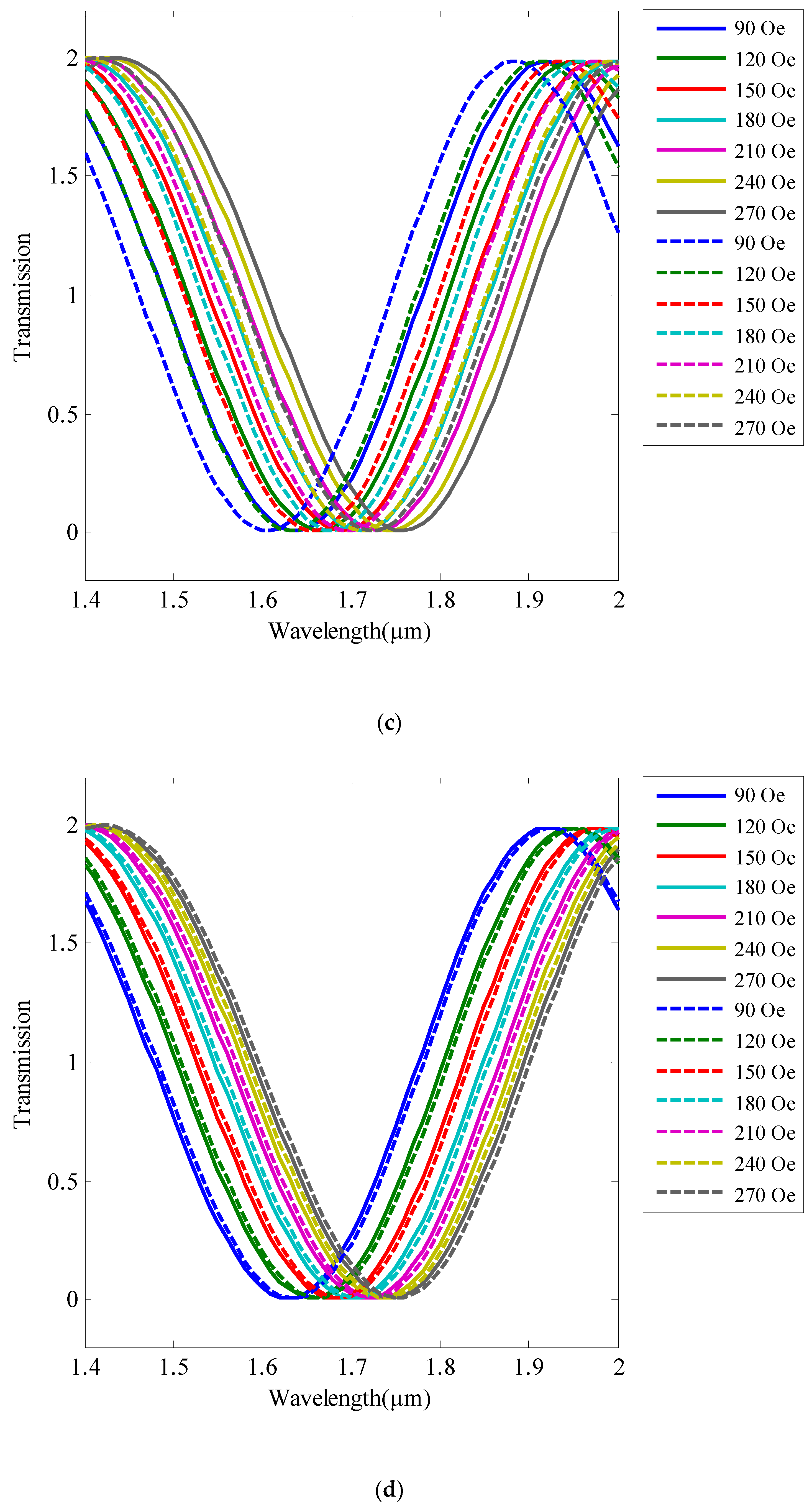
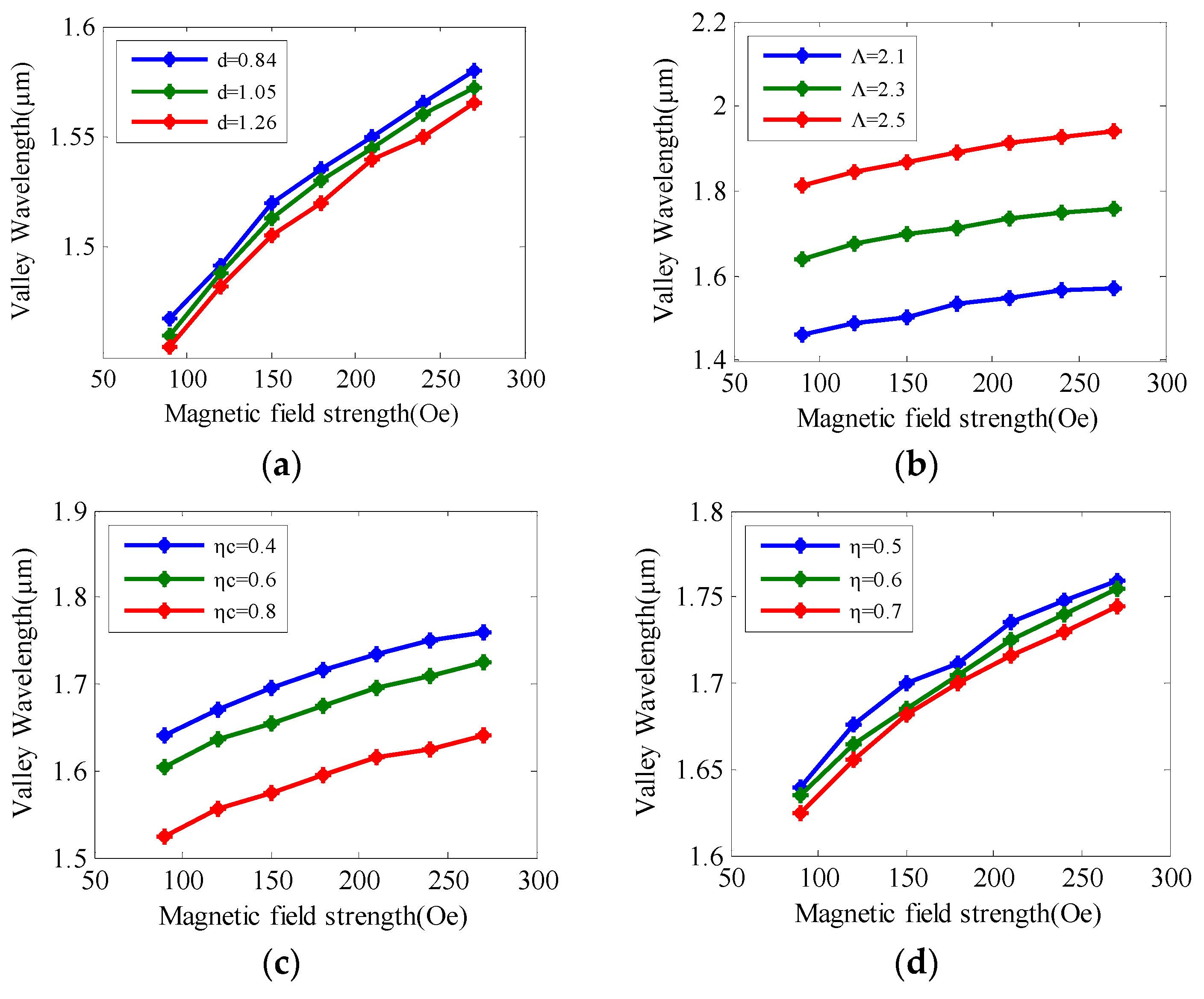
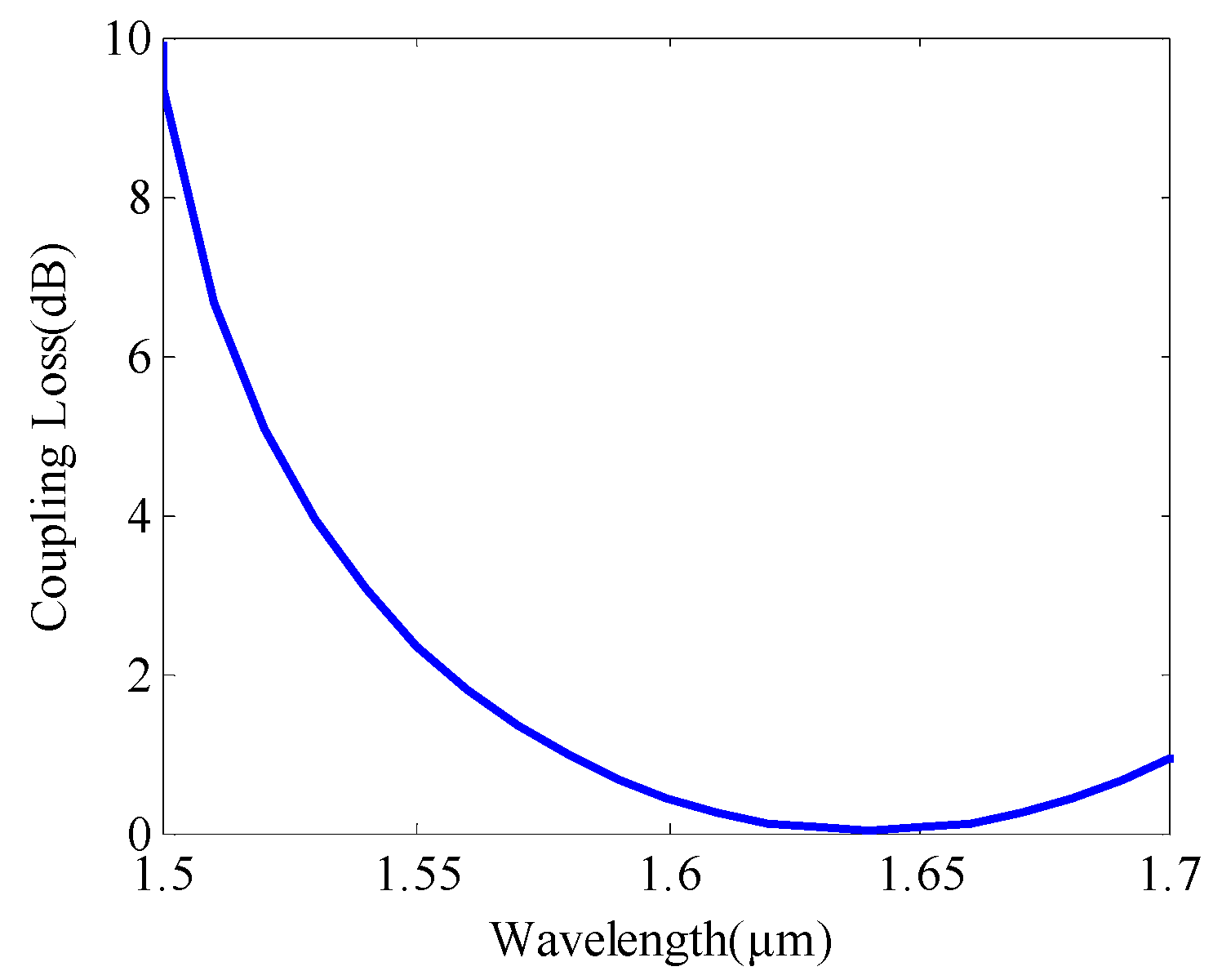
3.3. Output Optical Power, Magnetic Sensitivity, and Coupling Loss

The refractive index of a fiber core which is filled with magnetic fluid is different with different magnetic field environments, and the total transmission spectra of dual-core PCF changes accordingly. Figure 7 shows the total transmission spectra of dual-core PCF with different magnetic field strength when their structure parameters are set as cladding air hole diameter d = 1.05 μm, pitch Λ = 2.1 μm, and fiber length L = 1 mm. The transmission spectra of the dual-core PCFs approximate a sinusoidal curve. The dual-core PCFs used as a magnetic field sensor can be longer when the transmission spectrum is considered in a shorter wavelength range. As the magnetic field increases from 90 Oe to 120 Oe, the valley wavelength of the optical power for our PCF fiber shifts 28 nm to long wavelength, and there is 12.5 nm shifting when the magnetic field increases from 240 Oe to 270 Oe. There is a red shift of transmission spectrum. The greater the magnetic field, the smaller the shifting of the valley wavelength of the optical power. Therefore, the magnetic field intensity can be detected by measuring the valley wavelength of optical power at the output end of the dual-core PCF.
There are different transmission curves with different structure parameters. Figure 8a represents total transmission spectra when d changes and is solid curves when d = 0.84 μm and dashed curves when d = 1.05 μm. Figure 8b shows the transmission curves when the pitch (Λ) of the fiber changes. The transmission spectrum line is solid curves when Λ = 2.1 μm and dashed curves when Λ = 2.3 μm, because the increasing pitch causes the widening of the channel and the transmission curve shift. Figure 8c represents total transmission spectra when ηc changes, which is solid curves when ηc = 0.5 and dashed curves when ηc = 0.6. Figure 8d shows the total transmission curve shift with η changing, and the curve is solid curves when η = 0.6 and dashed curves when η = 0.7. We can see the structural parameter variation for a PCF-based magnetic field sensor must have effect on sensitivity, such as the distance between two air holes Λ, the diameter of circle holes of the cladding d, the ellipticity of elliptical air holes, and the magnetic fluid-filled holes ηc and η. The shifting of transmission curves depending on Λ is more significant than the other structure parameters. There is small shifting of the transmission curves with the ellipticity of elliptical air holes and the magnetic fluid-filled holes. This magnetic field sensor of PCF has strong robustness to the ellipticity of the elliptical air holes, although it is more difficult to make PCF with elliptical air holes.
Figure 9 shows the valley wavelength of the optical power with different magnetic field strength for different structural parameters of dual-core PCF. The slope of the curve is the magnetic sensitivity. As can be seen from Figure 9, with the increase in d, ηc, and η, the valley wavelength of the optical power decreases, and the valley wavelength of the optical power increases as the Λ increases. The magnetic field sensitivity decreases as the magnetic field increases, as shown in Figure 9, and the magnetic field sensitivity does not change much. When Λ = 2.3 μm, d = 1.15 μm, ηc = 0.4, and η = 0.5, the sensitivity curve of the magnetic field sensor is shown in Figure 10. The maximum magnetic field sensitivity is up to 1200 pm/Oe.
The coupling loss of PCF is defined as the ratio of the output power to the input power, which can be described by Equation (8) [26]. The normalized output power of PCF can be calculated by Equation (6), and the input power of PCF is reduced to 1; rewrite Equation (8) as Equation (9).
Loss = 10 l o g 10 P o u t P i n
Loss = 10 l o g 10 cos π λ n e x n o x + n e y n o y L · cos π λ n e x n o x + n e y n o y L
Figure 11 shows the coupling loss of PCF by varying wavelength at optimized structural parameters when the magnetic field is 90 Oe. We observe that the PCF has a minimum coupling loss of 0.04 dB at 1.65 µm, this means that most of the input power can couple into the output ports.
Finally, a comparison Table 1 has been inserted with several optical parameters. Here, it can be easily noticed that the suggested structure enhanced the sensing performances over the existing model. The magnetic field sensor we proposed has higher sensitivity. Furthermore, we analyzed the lower coupling length, coupling loss, and the birefringence of the fiber.

4. Conclusions

In this paper, we propose a novel structured magnetic field sensor based on dual-core PCF. In the fiber, there are two elliptical cores filled with magnetic fluid (Fe3O4). Coupling length, birefringence, and sensitivity variation with changing structural parameters are studied by using FEM. The coupling length of the fiber is fewer than 0.6 mm, indicating that the coupling of the two fiber cores is easier. The structure of two elliptic central holes and some elliptic cladding air holes increases the birefringence of the fiber, which is greater than 10−3, obtaining stronger ability of polarization maintaining. The externally applied magnetic field can be detected by measuring the valley wavelength of the optical power in the designed PCF sensor. The maximum sensitivity of the magnetic field sensor is up to 1200 pm/Oe. This designment provides a research basis for the design of the magnetic field sensor based on dual-core PCF filled with magnetic fluid.
Different geometrical structures of the dual-core PCF and different magnetic fluid materials may improve the performance of the magnetic field sensor. Magnetic field sensors with high sensitivity and practicability will be the direction of further research in the future.

Author Contributions

Conceptualization, J.X. and H.Y.; methodology, J.X. and H.Y.; software, J.X.; validation, J.X., Y.G. and H.Y.; formal analysis, J.X. and Y.G.; investigation, J.X.; resources, J.X.; data curation, J.X.; writing—original draft preparation, J.X.; writing—review and editing, J.X. and H.Y.; visualization, J.X.; supervision, J.X.; project administration, J.X. and H.Y.; funding acquisition, J.X. and H.Y. All authors have read and agreed to the published version of the manuscript.

Funding

This work was supported by the Project of National Defense Science and Technology Innovation Special Zone (18-163-00-XX-006-XXX-01), and the Project of Shandong Province Higher Educational Science and Technology Program (J18KA368).

Conflicts of Interest

The authors declare no conflict of interest.

References

  1. Aly, A.H.; Hsu, H.; Yang, T.; Wu, C.; Hwangbo, C. Extraordinary optical properties of a superconducting periodic multilayer in near-zero-permittivity operation range. J. Appl. Phys. 2009, 105, 083917–083923. [Google Scholar] [CrossRef]
  2. Aly, A.H. Metallic and Superconducting Photonic Crystal. J. Supercond. Nov. Magn. 2008, 21, 421–425. [Google Scholar] [CrossRef]
  3. Aly, A.H.; Mohamed, D. BSCCO/SrTiO3 One Dimensional Superconducting Photonic Crystal for Many Applications. J. Supercond. Nov. Magn. 2015, 28, 1699–1703. [Google Scholar] [CrossRef]
  4. Aly, A.H.; Ghany, S.; Kamal, B.M.; Vigneswaran, D. Theoretical studies of hybrid multifunctional YaBa2Cu3O7 photonic crystals within visible and infra-red regions. Ceram. Int. 2020, 46, 365–369. [Google Scholar] [CrossRef]
  5. Malek, C.; Aly, A.H.; Alamri, S.; Sabra, W. Tunable PBGs with a cutoff frequency feature in Fibonacci quasi-periodic designs containing a superconductor material at THz region. Phys. Scr. 2021, 96, 105501. [Google Scholar] [CrossRef]
  6. Sabra, W.; Aly, A.H. A Comparative study of the effective surface impedance of an HTc superconducting thin film from visible to mid-IR region. Opt. Quantum Electron. 2021, 53, 416. [Google Scholar] [CrossRef]
  7. Aly, A.H.; Sayed, F.A. THz cutoff frequency and multifunction Ti2Ba2Ca2Cu3O10/GaAs photonic bandgap materials. Int. J. Mod. Phys. B 2020, 34, 2050091. [Google Scholar] [CrossRef]
  8. Sayed, H.; Krauss, T.F.; Aly, A.H. Versatile photonic band gap materials for water desalination. Opt. Int. J. Light Electron Opt. 2020, 219, 165160. [Google Scholar] [CrossRef]
  9. Zaky, Z.A.; Ahmed, A.M.; Shalaby, A.S.; Aly, A.H. Refractive index gas sensor based on the Tamm state in a one-dimensional photonic crystal: Theoretical optimisation. Sci. Rep. 2020, 10, 9736. [Google Scholar] [CrossRef]
  10. Aly, A.H.; Mohamed, D.; Mohaseb, M.A. Biophotonic sensor for the detection of creatinine concentration in blood serum based on 1D photonic crystal. RSC Adv. 2020, 10, 31765–31772. [Google Scholar] [CrossRef]
  11. Zaky, Z.A.; Aly, A.H. Modeling of a biosensor using Tamm resonance excited by graphene. Appl. Opt. 2021, 60, 1411–1419. [Google Scholar] [CrossRef] [PubMed]
  12. Trabelsi, Y.; Ali, N.B.; Aly, A.H.; Kanzari, M.A. Tunable high Tc superconducting photonic band gap resonators based on hybrid quasi-periodic multilayered stacks. Phys. C Supercond. Appl. 2020, 576, 1353706. [Google Scholar] [CrossRef]
  13. Trabelsi, Y.; Belhadj, W.; Ali, N.B.; Aly, A.H. Theoretical Study of Tunable Optical Resonators in Periodic and Quasiperiodic One-Dimensional Photonic Structures Incorporating a Nematic Liquid Crystal. Photonics 2021, 8, 150. [Google Scholar] [CrossRef]
  14. Aly, A.H.; Malek, C.; Elsayed, H.A. Transmittance properties of a quasi-periodic one-dimensional photonic crystals that incorporate nanocomposite material. Int. J. Mod. Phys. B 2018, 32, 1850220. [Google Scholar] [CrossRef]
  15. Aly, A.H.; Nagaty, A.; Khalifa, Z. Propagation of acoustic waves in 2D periodic and quasiperiodic phononic crystals. Int. J. Mod. Phys. B 2017, 31, 1750147. [Google Scholar] [CrossRef]
  16. Birks, T.A.; Knight, J.C.; Russell, P.S. Endlessly single-mode photonic crystal fiber. Opt. Lett. 1997, 22, 961–963. [Google Scholar] [CrossRef]
  17. Russell, P. Photonic crystal fibers. Science 2003, 299, 358–362. [Google Scholar] [CrossRef]
  18. Li, J.; Wang, R.; Wang, J.; Liu, Y. Highly birefringent photonic crystal fibers with selectively liquid-filled structure in cladding. Opt. Eng. 2011, 50, 025001. [Google Scholar] [CrossRef]
  19. Ortigosa-Blanch, A.; Knight, J.C.; Wadsworth, W.J.; Arriaga, J.; Mangan, B.J.; Birks, T.A.; Russell, P.S.J. Highly birefringent photonic crystal fibers. Opt. Photonics News 2001, 12, 17. [Google Scholar] [CrossRef]
  20. Kabir, M.A.; Hassan, M.M.; Ahmed, K.; Rajan, M.S.M.; Aly, A.H.; Hossain, M.N.; Paul, B.K. Novel spider web photonic crystal fiber for robust mode transmission applications with supporting orbital angular momentum transmission property. Opt. Quantum Electron. 2020, 52, 331. [Google Scholar] [CrossRef]
  21. Jegadeesan, S. Design of a Polarization Splitter Based on a Dual-core Hexagonal-shaped Photonic Crystal Fiber. Curr. Opt. Potonics 2019, 3, 304–310. [Google Scholar]
  22. Zhao, T.; Lou, S.; Wang, X.; Zhou, M.; Lian, Z. Ultrabroadband Polarization-Insensitive Coupler Based on Dual-Core Photonic Crystal Fiber. IEEE Photonics J. 2017, 9, 4500510. [Google Scholar] [CrossRef]
  23. Wang, J.; Pei, L.; Wang, J.; Ruan, Z.; Zheng, J.; Li, J.; Ning, T. Magnetic field and temperature dual-parameter sensor based on magnetic fluid materials filled photonic crystal fiber. Opt. Express 2020, 28, 1456–1471. [Google Scholar] [CrossRef] [PubMed]
  24. Li, P.; Zhao, J. Polarization-dependent coupling in gold-filled dual-core photonic crystal fibers. Opt. Express 2013, 21, 5232–5238. [Google Scholar] [CrossRef]
  25. Sun, B.; Chen, M.; Zhang, Y.; Zhou, J. Polarization-dependent coupling characteristics of metal-wire filled dual-core photonic crystal fiber. Opt. Quantum Electron. 2014, 47, 441–451. [Google Scholar] [CrossRef]
  26. Xu, Q.; Luo, W.; Li, K.; Copner, N.; Lin, S. Design of Polarization Splitter via Liquid and Ti Infiltrated Photonic Crystal Fiber. Crystals 2019, 9, 103. [Google Scholar] [CrossRef]
  27. Huang, Y.; Wang, Y.; Zhang, L.; Shao, Y.; Zhang, F.; Liao, C.; Wang, Y. Tunable Electro-Optical Modulator Based on a Photonic Crystal Fiber Selectively Filled with Liquid Crystal. J. Light. Technol. 2019, 37, 1903–1908. [Google Scholar] [CrossRef]
  28. Priya, K.R.; Raja, A.S.; Sundar, D.S. Design of a dual-core liquid-filled photonic crystal fiber coupler and analysis of its optical characteristics. J. Opt. Technol. 2016, 83, 569–573. [Google Scholar] [CrossRef]
  29. Wang, E.; Cheng, P.; Li, J.; Cheng, Q.; Zhou, X.; Jiang, H. High-sensitivity temperature and magnetic sensor based on magnetic fluid and liquid ethanol filled micro-structured optical fiber. Opt. Fiber Technol. 2020, 55, 102161. [Google Scholar] [CrossRef]
  30. Lou, J.; Cheng, T.; Li, S. High sensitivity photonic crystal fiber sensor based on dual-core coupling with circular lattice. Opt. Fiber Technol. 2019, 48, 110–116. [Google Scholar] [CrossRef]
  31. Wang, Y.; Li, S.; Li, J.; Zhang, Z.; Zhang, S.; Wu, J. High-sensitivity photonic crystal fiber refractive index sensor based on directional coupler. Opt. Fiber Technol. 2019, 49, 16–21. [Google Scholar] [CrossRef]
  32. Tao, Y.; Ye, H.; Ding, Y.; Ren, X.; Liu, X. Refractive Index Sensing Simulations of CsPbBr3 Quantum Dots/Gold Bilayer Coated Triangular-Lattice Photonic Crystal Fibers. Photonic Sens. 2022, 12, 220309. [Google Scholar] [CrossRef]
  33. Wang, S.; Liu, Y.; Wang, Z.; Han, T.; Xu, W.; Wang, Y.; Wang, S. Intermodal interferometer based on a fluid-filled two-mode photonic crystal fiber for sensing applications. Appl. Opt. 2013, 52, 3166–3171. [Google Scholar] [CrossRef] [PubMed]
  34. Amiri, I.S.; Paul, B.K.; Ahmed, K.; Aly, A.H.; Zakaria, R.; Yupapin, P.; Vigneswaran, D. Tri-core photonic crystal fiber based refractive index dual sensor for salinity and temperature detection. Microw. Opt. Technol. Lett. 2019, 61, 847–852. [Google Scholar] [CrossRef]
  35. Liu, H.; Wang, H.; Chen, C.; Zhang, W.; Zhang, S.; Wang, Q.; Ding, Y. Highly sensitive and temperature-compensated fiber bending sensing based on directional resonance coupling in photonic crystal fibers. Opt. Fiber Technol. 2019, 47, 164–171. [Google Scholar] [CrossRef]
  36. Liang, H.; Zhang, W.; Wang, H.; Geng, P.; Zhang, S.; Gao, S.; Yang, C.; Li, J. Fiber in-line Mach-Zehnder interferometer based on near-elliptical core photonic crystal fiber for temperature and strain sensing. Opt. Lett. 2013, 38, 4019–4022. [Google Scholar] [CrossRef]
  37. Paulabc, B.K.; Ahmed, K.; Dhasarathan, V.; Al-Zahrani, F.A.; Aktar, M.N.; Uddin, M.S.; Aly, A.H. Investigation of gas sensor based on differential optical absorption spectroscopy using photonic crystal fiber. Alex. Eng. J. 2020, 59, 5045–5052. [Google Scholar]
  38. An, G.; Li, S.; An, Y.; Wang, H.; Zhang, X. Glucose sensor realized with photonic crystal fiber-based Sagnac interferometer. Opt. Commun. 2017, 405, 143–146. [Google Scholar] [CrossRef]
  39. Natesan, A.; Govindasamy, K.P.; Gopal, T.R.; Dhasarathan, V.; Aly, A.H. Tricore photonic crystal fibre based refractive index sensor for glucose detection. IET Optoelectron. 2019, 13, 118–123. [Google Scholar] [CrossRef]
  40. Mathews, S.; Farrell, G.; Semenova, Y. Liquid crystal infiltrated photonic crystal fibers for electric field intensity measurements. Appl. Opt. 2011, 50, 2628–2635. [Google Scholar] [CrossRef]
  41. Gao, R.; Jiang, Y.; Abdelaziz, S. All-fiber magnetic field sensors based on magnetic fluid-filled photonic crystal fibers. Opt. Lett. 2013, 38, 1539–1541. [Google Scholar] [CrossRef] [PubMed]
  42. Li, J.H.; Wang, R.; Wang, J.; Zhang, B.; Xu, Z.; Wang, H. Novel magnetic field sensor based on magnetic fluids infiltrated dual-core photonic crystal fibers. Opt. Fiber Technol. 2014, 20, 100–105. [Google Scholar] [CrossRef]
  43. Gangwar, R.K.; Bhardwaj, V.; Singh, V.K. Magnetic field sensor based on selectively magnetic fluid infiltrated dual-core photonic crystal fiber. Opt. Eng. 2016, 55, 026111. [Google Scholar] [CrossRef]
  44. Chen, H.; Li, S.; Li, J.; Fan, Z. Magnetic Field Sensor Based on Magnetic Fluid Selectively Infilling Photonic Crystal Fibers. IEEE Photonics Technol. Lett. 2015, 27, 717–720. [Google Scholar] [CrossRef]
  45. De, M.; Singh, V.K. Magnetic fluid infiltrated dual core photonic crystal fiber based highly sensitive magnetic field sensor. Opt. Laser Technol. 2018, 106, 61–68. [Google Scholar] [CrossRef]
  46. Liu, Q.; Xing, L.; Wu, Z. The highly sensitive magnetic field sensor based on photonic crystal fiber filled with nano-magnetic fluid. Opt. Commun. 2019, 452, 238–246. [Google Scholar] [CrossRef]
  47. Guo, K.; Zhou, J.; He, J.; Liao, C.; Wang, Y.; Li, Z.; Yang, K.; Liu, S.; Wang, Y. An All-Fiber Fan-Out Device for Varying Twin-Core Fiber Types. J. Lightwave Technol. 2017, 35, 5121–5126. [Google Scholar] [CrossRef]
  48. Chen, Y.F.; Yang, S.Y.; Tse, W.S.; Horng, H.E.; Hong, C.Y.; Yang, H.C. Thermal effect on the field-dependent refractive index of the magnetic fluid film. Appl. Phys. Lett. 2003, 82, 3481–3483. [Google Scholar] [CrossRef]
  49. Wang, X.Y.; Li, S.; Cheng, T.; Li, J. Overview of photonic devices based on functional material-integrated photonic crystal fibers. J. Phys. D Appl. Phys. 2022, 55, 273001. [Google Scholar] [CrossRef]
  50. Saitoh, K.; Sato, Y.; Koshiba, M. Coupling characteristics of dual-core photonic crystal fiber couplers. Opt. Express 2003, 11, 3188–3195. [Google Scholar] [CrossRef]
  51. Huang, W.P. Coupled-mode theory for optical waveguides:an overview. J. Opt. Soc. Am. A 1994, 11, 963–983. [Google Scholar] [CrossRef]
Figure 1. Cross-section of designed magnetic fluid-filled dual-core PCF magnetic field sensor.
Crystals 12 01383 g001
Figure 2. The experimental setup of the magnetic field sensor.
Crystals 12 01383 g002
Figure 3. Electric field of four fundamental supermodes in the proposed dual-core PCF. The arrows indicate the direction of the electric field vectors. (a) x polarize even mode, (b) x polarize odd mode, (c) y polarize even mode, and (d) y polarize odd mode.
Crystals 12 01383 g003
Figure 4. Coupling length for x and y polarizations with varying wavelength when the magnetic field is 90 Oe, d is 0.84 μm, and Λ is 2.1 μm.
Crystals 12 01383 g004
Figure 5. Coupling length of x-polarized input light with varying structure parameters. (a) Coupling length with different d/Λ, (b) coupling length with different Λ, (c) coupling length with different ηc, and (d) coupling length with different η.
Crystals 12 01383 g005
Figure 6. Variation of birefringence in the proposed dual-core PCF. (a) Birefringence at different d/Λ with varying wavelength. (b) Birefringence at different Λ with varying wavelength. (c) Birefringence at different ηc with varying wavelength. (d) Birefringence at different η with varying wavelength.
Crystals 12 01383 g006
Figure 7. The total transmission spectra of dual-core PCF with different magnetic field strength.
Crystals 12 01383 g007
Figure 8. The total transmission spectra of dual-core PCF with different structure parameters. (a) Transmission spectra with different d = 0.84 (solid curve) and 1.05 (dashed curve), (b) transmission spectra with different Λ = 2.1 (solid curve) and 2.3 (dashed curve), (c) transmission spectra with different ηc = 0.5 (solid curve) and 0.6 (dashed curve), and (d) transmission spectra with different η = 0.6 (solid curve) and 0.7 (dashed curve).
Crystals 12 01383 g008aCrystals 12 01383 g008b
Figure 9. The valley wavelength of the optical power with different magnetic field strength. (a) The valley wavelength for different d. (b) The valley wavelength for different Λ. (c) The valley wavelength for different ηc. (d) The valley wavelength for different η.
Crystals 12 01383 g009
Figure 10. The sensitivity of the magnetic field sensor.
Crystals 12 01383 g010
Figure 11. The coupling loss of the PCF.
Crystals 12 01383 g011
Table 1. Comparisons of essential properties of previous PCFs with the suggested PCF.
PCFsCoupling LengthCoupling LossBirefringence
(×10−3)
Sensitivity
Ref. [26]2.352 mm--4.8 pm/Oe
Ref. [27]1.13 mm--305.8 pm/Oe
Ref. [29]0.67 mm--799.07 pm/Oe
Proposed0.42 mm0.040.991200 pm/Oe
Publisher’s Note: MDPI stays neutral with regard to jurisdictional claims in published maps and institutional affiliations.

