Abstract
The effects of different brazing processes on the interfacial microstructure and shear strength of TiZrHfNbMo high-entropy alloy (HEAS) and Si3N4 ceramic brazed joints were studied. There is no obvious defect in a brazed TiZrHfNbMo HEAS/AgCuTi/Si3N4 ceramic joint, and the two materials have good metallurgical bonding. The typical interface microstructure is Si3N4/Ti5Si3/Ag solid solution +Cu (s,s)+ CuTi/Cu2Ti/Cu4Ti + TiCu(Hf,Zr)NbMo/TiZrHfNbMo HEAs. With the increase of brazing temperature, the dispersed CuTi phase agglomerates in the brazed joint, and acts as the nucleate of the Cu-based solid solution. The thickness of the reaction layer increases with the increase of phases in the reaction layer on both sides of the joint. When the brazing temperature is 800 °C, 820 °C, 840 °C and 860 °C, the shear strength of the brazed joint is 30 MPa, 72 MPa, 86 MPa and 21 MPa, respectively. The formation of CuTi and Ti5Si3 intermetallic compounds increases the thickness of the reaction layer, and improves the strength of the joint. However, excessive CuTi and Ti5Si3 intermetallic compounds lead to a significant decrease in joint strength. The grain coarsening of the joint can also affect the strength of the joint.
1. Introduction
Due to the characteristics of high mixing entropy, lattice distortion, hysteresis diffusion and cocktail effect, high-entropy alloys have attracted wide attention due to their excellent properties such as high hardness, temper-softening resistance, good deterioration, oxidation resistance and corrosion resistance [1,2,3]. Among these high-entropy alloys, TiZrHfNbMo high-entropy alloy has a good application in aerospace field with its excellent properties [4,5]. At the same time, it has good weldability [4,5]. Si3N4 ceramics have excellent physical and mechanical properties, such as high strength, elastic modulus, hardness, corrosion resistance and wear resistance, and have been widely used in engineering [6,7,8]. Si3N4 ceramic is an ideal wave-transparent material for missile radome in practical production. Therefore, the combination of TiZrHfNbMo high-entropy alloy and Si3N4 ceramic will expand their application fields, especially in the aerospace field. However, brittleness makes it difficult for Si3N4 ceramics and TiZrHfNbMo high-entropy alloys to form products of large size and complex shape [9,10], which greatly limits their application fields. For example, reliable connection between Si3N4 ceramics and high-entropy alloys is the key to the fabrication of radar radome for ultrahigh-sound-velocity aircraft.
In order to solve this problem, a variety method of ceramic–metal joining methods have been studied, including brazing [11,12], diffusion welding [13,14], partial transient liquid phase bonding (TLP) [15,16] etc. Among all kinds of joining technologies, brazing has become the most effective method to combine ceramic and metal due to its advantages of low joining temperature, low pressure and unlimited joining forms [17,18,19]. However, the poor wettability and high residual stress of the ceramic–metal joint are two main problems that restrict its application. Poor wettability makes it difficult to join ceramics and metals. The mismatch of thermal expansion coefficient (CTE) and Young’s modulus of ceramic, brazing seam and metal will lead to high residual stress in the brazed joint. The high residual stress will lead to cracks in the joint, which will reduce the strength of the joint. Therefore, a lot of research has been done to solve these problems. The effective methods are composite fillers, interlayer structures and active fillers etc. [20,21,22,23]. For example, Y. X. Zhao et al. [21] brazed TC4 alloy and Si3N4 ceramics with nano Si3N4 particles and micro Ti particles reinforced AgCu filler. Y. P. Liu et al. [22] brazed ZS ceramic and Inconel 600 alloy with AgCu-Cu foam composite filler. G. Song et al. [23] successfully brazed TiAl based alloy and Si3N4 ceramics with AgCuTi filler, and the maximum shear strength reached 115 MPa. Compared with the traditional AgCu filler, the active filler AgCuTi has good ductility and wettability [24,25,26], which makes the Si3N4 ceramic and alloy form a good structure. In view of this, this paper uses AgCuTi filler to connect TiZrHfNbMo high-entropy alloy and Si3N4 ceramic, in order to solve the two main problems of poor wettability and large residual stress.
2. Materials and Methods
Si3N4 ceramic (provided by Beijing Kaifa Special Ceramics Co., Ltd. Bijing, China) was used as the matrix material in the experiment. The raw materials for preparing TiZrHfNbMo include Ti, Zr, HF, Nb and Mo. The purity of TiZrHfNbMo metal is higher than 99.9%. TiZrHfNbMo is a body centered cubic (BCC) solid solution alloy ingot prepared by arc melting in a water-cooled copper crucible repeated five times. The high-entropy alloy was cut into blocks (4 mm × 4 mm × 4 mm). The size of the Si3N4 ceramic sample used for the shear strength test was 10 mm × 10 mm × 4 mm, and the size used for OM (optical microscopy) was 4 mm × 4 mm × 4 mm.
Before brazing, the brazing surfaces of the TiZrHfNbMo high-entropy alloy and Si3N4 sample were polished with SiC sandpaper (800 mesh), and then ultrasonically cleaned in alcohol for 10 min. Then AgCuTi powder filler (6.8.8Ag-26.7Cu-4.5Ti) and binder (provided by Zhejiang Hangzhou general brazing materials Co., Ltd., Hangzhou, China) were evenly mixed into filler paste and coated between the Si3N4 ceramics and high-entropy alloy as shown in Figure 1a. TiZrHfNbMo high-entropy alloy, AgCuTi filler and Si3N4 ceramics were placed in a sandwich model. The Mo block was placed above the joint to ensure full contact between the filler and the base metal during brazing. Finally, the graphite mold was carefully put into the vacuum furnace. At the beginning of the brazing process, the furnace was heated to 300 °C at the rate of 10 °C/min, and then kept for 30 min to volatilize the residual gas. The temperature was then heated at a rate of 10 °C/min to the target brazing temperature of 800 to 860 °C. The brazing sample was kept at brazing temperature for 60 min, and then cooled to 300 °C at the rate of 5 °C/min. Finally, the joint was cooled to room temperature in the furnace. During brazing, the vacuum should be kept at 1.5–2.0 ×10⁻³ pa to avoid oxidation. The microstructure and phase composition of the brazed samples was determined by scanning electron microscopy (SEM, su-8010, Hitachi, Japan) and energy dispersive spectrometer (EDS). A J5070-1/ZF cutter was used to cut the specimen for phase analysis along the direction perpendicular to the welding surface, and the X-ray diffraction (XRD, Bede D1, (XRD, Brooke, German) patterns were measured with Cuk α at a scanning rate of 2°/min. The shear strength of the joint was measured by Instron 5500 testing machine at room temperature. Figure 1b is the schematic diagram of the shear test. The average shear strength of brazed joint was calculated by five groups of test results at the same brazing temperature.
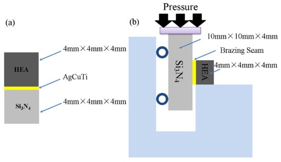
Figure 1.
Schematic diagram of (a) brazing assembly and (b) shear test.
3. Results and Discussions
3.1. Microstructure of TiZrHfNbMo High-entropy alloy/AgCuTi/Si3N4 Brazed Joints
Figure 2 shows the typical microstructure of TiZrHfNbMo high-entropy alloy/AgCuTi/Si3N4 joint brazed at 840 °C for 60 min. It can be seen from the figure that the joint is well connected, and there are no cracks, pores and other defects in the weld. The whole interface of the joint is divided into three areas, which are marked as zone I, zone II and zone III (as shown in Figure 2a). In order to study the interface microstructure of the joint, EDS analysis was carried out on the typical microstructure (the characteristic phase is marked as A–G in Figure 2b–f), and the analysis results are shown in Table 1. EDS results show that the gray A phase is rich in Ag, which means that an Ag-based solid solution (Ag (s, s)) was formed in the joint. The gray phase B is Cu (s, s) [22,23]. The dark gray C phase surrounded by B phase is mainly composed of Cu and Ti, and its atomic ratio is about 1:1, so the dark gray phase C is CuTi phase. In region III, the dark gray D phase is mainly composed of Cu, Ti and Si, and the atomic ratio of elements is about Cu: Ti = 1:1, Ti:Si = 5:3. Therefore, it is inferred that the D phase is CuTi + Ti5Si3 [24]. In order to further study the interface microstructure of region I, the reaction layer structure region in Figure 2d is enlarged and shown in Figure 2e,f. It can be seen from Figure 2e that the dark phase E is composed of Cu and Ti, and its atomic ratio is close to Cu:Ti = 4:1. Based on the Cu-Ti binary phase diagram, it can be concluded that the E phase is Cu4Ti. The elements in phase F are Ti, Cu, Zr, HF, Nb and Mo, and the atomic ratio of Ti: Cu: (HF, Zr): NB: Mo is approximately 1:1:1:1. Therefore, it can be inferred that phase F is a solid solution phase TiCu(Hf,Zr)NbMo. The content of Cu in the G phase is 63.74 at.%, so the G phase is Cu (s, s). The H phase is composed of Cu and Ti, and its atomic ratio is close to 2:1, therefore, the H phase is Cu2Ti. The phase composition of the brazed joint is shown in Figure 3. It is further confirmed that the joint is composed of Ag (s, s), Cu (s, s), Cu2Ti, CuTi, Ti5Si3, TiZrHfNbMo, Cu4Ti [27]. The amount of the Cu2Ti is so small that it cannot be detected. Therefore, the interface structure of TiZrHfNbMo high-entropy alloy/Si3N4 joint is determined as TiZrHfNbMo high-entropy alloy/Cu4Ti + TiCu(Hf,Zr)NbMo/Cu2Ti + Ag(s, s) + Cu(s, s) + CuTi/Ti5Si3/Si3N4.
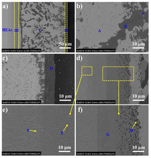
Figure 2.
Typical microstructure of TiZrHfNbMo HEAs/AgCuTi/Si3N4 joint brazed at 840 °C for 60 min. (a) Typical interfacial microstructure, (b) zone III, (c) interfacial microstructure of zone I and zone II, (d) interfacial microstructure of zone I and zone III, (e) and (f) Enlarged drawing of two areas in (d).

Table 1.
EDS analysis of phases in Figure 2 (at. %).
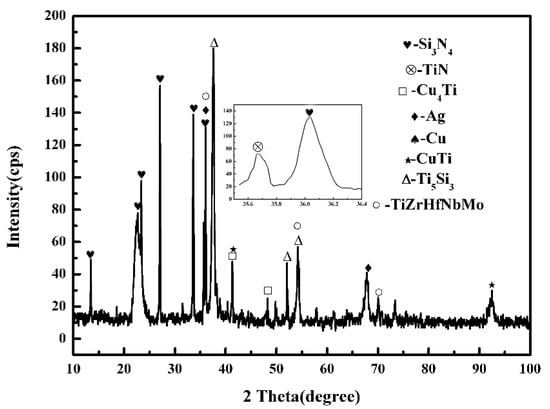
Figure 3.
XRD pattern of brazed joint at 840 °C for 60 min.
The typical cross section of the TiZrHfNbMo HEAS and Si3N4 ceramic joint brazed at 840 °C with AgCuTi filler is shown in Figure 4. It can be seen from Figure 4b–i that Ag, Cu, Ti, Si, Zr, Nb, Mo, and Hf are the main elements in brazed joint. Ag is mainly distributed in zone I, as can be seen in Figure 4b, as Ag is inert and has no obvious diffusion. According to Figure 4c, Cu is distributed in zone I and II. On the one hand, driven by the concentration gradient, the Cu element in the liquid filler diffuses to the zone I. On the other hand, it is because the residual Cu remains in zone II of brazing center due to the decrease of concentration.
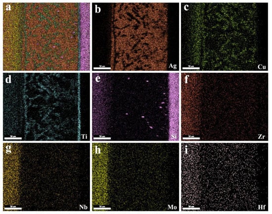
Figure 4.
Elemental analysis results of the TiZrHfNbMo HEAs/AgCuTi/Si3N4 joint brazed at 840 °C. (a) Interfacial microstructure; (b–i) element distribution of Ag, Cu, Ti, Si, Zr, Nb, Mo, and Hf.
Figure 4d shows that Ti completely diffuses the whole joint and evenly distributes in zones I, II and III, and active element Ti preferentially diffuses to Si3N4 ceramic, forming reaction layer zone II and preventing the diffusion of Cu to the ceramic side. Figure 4e shows that Si element is mainly concentrated in Si3N4 ceramic and partially diffuses to zone II, which may be due to the different chemical bond types of Si-N bond and AgCuTi filler in Si3N4, and the Si-N bond energy is as high as 355 kJ/mol, so Si element diffuses slowly at the ceramic interface. Figure 4c,d and Figure 4f–i are the distribution maps of elements Ti, Zr, Nb, Mo and Hf in TiZrHfNbMo high-entropy alloy. The results show that the elements are basically located in the base metal of the high-entropy alloy, and there is no obvious diffusion, which is due to the slow diffusion rate of high-entropy alloy. The element distribution in the interface indicates the atomic diffusion between the TiZrHfNbMo high-entropy alloy/AgCuTi interface and AgCuTi/Si3N4 interface.
The microstructure of the brazed joint at different temperatures is shown in Figure 5. It can be inferred that with the increase of the brazing temperature, the width of the reaction zone of the joint changes obviously. The changes of the three brazing reaction zones (zone I, zone II and zone III) are listed in Table 2. With the increase of brazing temperature, the Cu and Ti elements in the filler are fully combined in the zone I, and more TiCu intermetallic compounds are generated, such as CuTi and Cu2Ti phases. The existence of CuTi and Cu2Ti phases provides nucleation sites for the surplus copper in the filler, thus forming dispersed Cu (s, s) which depends on the CuTi and Cu2Ti phases. At the same time, the dispersed small Cu (s, s) are combined to form large Cu (s, s), which leads to the coarsening of the structure in zone I [23,27,28]. As a result, the amount of fine-grained Cu-based solid solution decreases, a large Cu (s, s) appears, and the width of i-zone changes obviously. Meanwhile, the wetting and spreading of filler can accelerate the fracture of Si-N bond, more Si elements diffuse to zone III and react with Ti elements in filler to form Ti5Si3 phase, which widens the thickness of reaction layer. It can also be seen from Table 2 that the thickness of reaction layer in zone II increases from 2 μm at 800 °C to 8 μm at 840 °C.
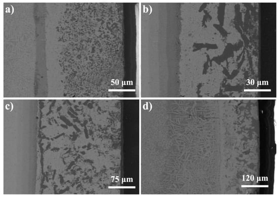
Figure 5.
The microstructures of the joints brazed at different temperatures. (a) 800 °C, (b) 820 °C, (c) 840 °C, (d) 860 °C.
Table 2.
Width of each zone under different brazing parameters.
The SEM images of the reaction layer II of the joint brazed at different temperatures are shown in Figure 6. It can be seen that the phase composition of brazing reaction layer has no obvious change. However, with the increase of brazing temperature, the width of zone II increases significantly. When the brazing temperature is between 800 °C and 840 °C, the thickness of zone II increases from 2 μm to 8 μm. When the brazing temperature reaches 860 °C, the width decreases to 6 μm. The reason is that, at 860 °C, more intermetallic phases of CuTi and Cu2Ti are formed in the joint, and a small amount of Ti diffuses to the ceramic side and reacts with Si to form Ti5Si3. Therefore, with the increase of brazing temperature, the width of zone II first increases and then decreases. With the increase of brazing temperature, the Cu element in the filler metal diffuses to the high-entropy alloy side (zone III), part of Cu element is dissolved in the high-entropy alloy to form TiCu(Hf,Zr)NbMo phase, and part of the Cu element diffuses into the high-entropy alloy and combines with the Ti element to form the Cu4Ti phase, which greatly increases the thickness of the reaction layer, Therefore, the width of zone III increases from 20 μm to 240 μm.
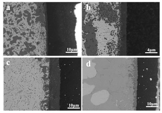
Figure 6.
The backscattered images of joints brazed at different temperatures (a) 800 °C, (b) 820 °C, (c) 840 °C, (d) 860 °C.
The mechanism of atom diffusion and reaction during brazing is shown in Figure 7. The initial state of brazing interface and the main atomic composition of brazing base metal and filler metal are shown in Figure 7a–c. At this stage, due to the low temperature, the AgCuTi filler does not melt, and there is no obvious atomic diffusion and chemical reaction at the interface. When the temperature reaches the melting point of the filler, the liquid filler begins to spread and wet the base metal, and the elements in the filler begin to diffuse to both sides of the substrates. During the brazing holding stage, the filler metal diffuses to the base metal rapidly, and the elements at the interface of the base metal also begin to diffuse slowly to the filler metal [29]. Finally, the base metal and filler are fully diffused and combined by metallurgical reaction to form a good joint. Figure 7e–g shows the interfacial reaction process and the formation mechanism of phases in the brazing process. More details are discussed as follows:
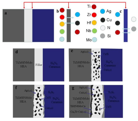
Figure 7.
Schematic diagram of microstructural evolution of TiZrHfNbMo HEAs/Si3N4 brazed joint. (a) Schematic diagram of brazing interfacial, (b) Interface between zone I and zone III, (c) Interface between zone I and zone II, (d) Brazing assembly diagram, (e–g) Atom diffusion and phase generate during brazing.
(1) Zone I: in the center of the brazing joint, Ti and Cu atom in the AgCuTi filler fully diffuse to the high-entropy alloy and Si3N4 ceramics. AgCuTi filler deviates from eutectic composition due to atomic diffusion, and forms Ag (s, s) and Cu (s, s). In addition, the active Ti reacts with Cu to form the CuTi phase. Therefore, as shown in Figure 8e, the main phases in the center of the joint are Ag (s, s), Cu (s, s), CuTi and Cu2Ti. It can be seen from Figure 2d that a large amount of Ti is enriched in Cu during brazing. The reaction between Ti and Cu produces a large number of TiCu compounds, and can be represented as follows:
2Ti + Cu = CuTi2
ΔG = −17069 + 4.887 T = −12969.8 J/mol
Ti + Cu = CuTi
ΔG = −17130 + 5.708 T = −12335.28 J/mol
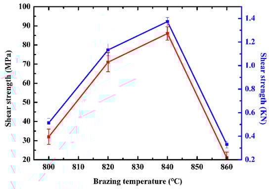
Figure 8.
Effect of brazing temperature on the shear strength of TiZrHfNbMo HEAs/Si3N4 joints brazed.
According to the analysis of reaction equation, the Gibbs free energy of the formation of CuTi phase is lower than that of CuTi2 phase, so the reaction of Ti with Cu produces CuTi phase. The remaining Cu element takes the CuTi phase as the nucleus and forms the Cu-based solid solution. Therefore, the Cu (s, s) coated CuTi phase appears in zone II.
(2) Zone II: with the temperature rises to the brazing temperature, AgCuTi filler melts and wets the base metal interface. The interface reaction is that Ti and Cu elements continue to diffuse and accumulate in the ceramic side (zone III) during brazing, and Si3N4 begins to decompose due to the wetting of the active filler, as shown in Figure 7c. The Ti element diffuses to the ceramic side first, and forms TiN and Ti5Si through the reaction of Ti + N→TiN, 5Ti + 3Si→Ti5Si3 with the Si and N elements which decomposed at the ceramic interface [14]. The specific reaction equation is as follows:
Ti + 1/4 Si3N4→TiN + 3/4Si
ΔG = −613,000 + 40.8 T = −578,728 J/mol
5Ti + 3Si→Ti5Si3
ΔG = −194,140 + 16.74 T = −180,078.4 J/mol
(3) Zone III: combined with Figure 4c, it can be found that a large number of Cu elements are concentrated in the high-entropy alloy side during brazing. However, as the high-entropy alloy in this work belongs to the refractory high-entropy alloy, the hysteresis diffusion effect and brazing temperature of the high-entropy alloy are far lower than its melting point, so there is no obvious diffusion of elements in the base metal side of high-entropy alloy. However, the Cu element in the filler diffuses into the high-entropy alloy to replace Zr element, and a new solid solution phase TiCu(Hf,Zr)NbMo is formed. At the same time, more Cu and Ti elements diffuse to the high-entropy alloy side and form Cu4Ti phase in the zone I:
Ti + 4Cu = Cu4Ti
ΔG = −7603 +3.12 T = −4982.2 J/mol
3.2. Mechanical Properties of TiZrHfNbMo High-entropy alloy/AgCuTi/Si3N4 Brazed Joints
Figure 8 shows the shear strength of brazed TiZrHfNbMo high-entropy alloy/Si3N4 joint at different temperatures from 800 °C to 860 °C. When the brazing temperature is 800 °C, the shear strength of the joint is only 30 MPa. The reason is that the brazing temperature is close to the melting point of the filler, and the incomplete melting of the filler leads to the insufficient wetting and spreading between the filler and the matrix, resulting in poor bonding of the joint interface. The shear strength increases rapidly to 72 MPa and 86 MPa when the temperature reaches 820 °C and 840 °C. The reason is that with the increase of temperature, Cu and Ti elements in the filler fully diffuse to the interface between high-entropy alloy base metal and Si3N4 ceramic, forming a reaction layer, which makes a good brazing joint between the filler and base metal. New TiCu(Hf,Zr)NbMo solid solution phase and Cu4Ti phase are generated on the side of high-entropy alloy (zone I), which makes the filler combine with the high-entropy alloy well. On the Si3N4 side (zone III), the TiN + Ti5Si3 reaction layer improves the interface bonding between filler and Si3N4. However, the intermetallic compounds (Cu4Ti, Ti5Si3) with high strength and hardness formed in the reaction layer (zone I, zone III) on both sides of the brazed joint increase the thickness of the reaction layer and significantly improve the strength of the brazed joint. When the temperature rises to 880 °C, a large number of intermetallic compounds Cu4Ti, TiN, and Ti5Si3 are formed in the brazing process, while too many brittle phases leads to the weakening of the stress relief ability of the joint through plastic deformation, and the joint strength gradually decreases to 21 MPa. Moreover, due to the large difference of Young’s modulus and thermal expansion coefficient between Si3N4 and filler, the increase of brazing temperature will produce large residual stress at the interface, and the higher residual stress will lead to microcracks at the interface, thus reducing the performance of the brazed joint [30,31,32,33]. On the other hand, the amount of brittle intermetallic compounds (Cu4Ti, TiN, Ti5Si3) at the interface increases, while the formation of excessive intermetallic compounds greatly increases the brittleness of the brazed joint and reduces the strength of the joint.
The fracture morphology of the sample after shear strength test is shown in Figure 9. Figure 9a show the fracture joint when the brazing temperature is 800 °C. It can be clearly observed that the fracture interface is mainly composed of brazing seam metal and a small amount of Si3N4, and the fracture position is in the reaction layer between filler and ceramic. Figure 9b,c shows fracture joints at 820 °C and 840 °C, respectively. It can be seen that there are large pieces of Si3N4 ceramics at the joint. In Figure 9d, the fracture morphology of the joint can be observed. The results show that the fracture position of the joint is in the reaction layer, and there are microcracks in the fracture morphology. As the crack has a significant influence on the properties of the joint, the shear strength is greatly reduced. When the brazing temperature is 800 °C, a thin reaction layer is formed between the filler metal and Si3N4 ceramic, which reduces the properties of the brazed joint. However, when the brazing temperature increases to 820 °C and 840 °C respectively, a new TiCu(Hf,Zr)NbMo solid solution phase and Cu4Ti phase reaction layer are formed between filler and high-entropy alloy. When the brazing temperature is 860 °C, the intermetallic compounds Cu4Ti, TiN, and Ti5Si3 in the reaction layer between the filler metal and the base metal increase and coarsen, which greatly increases the brittleness. Moreover, due to the difference of thermal expansion coefficient between filler metal and substrate, high brazing temperature leads to stress concentration, resulting in crack initiation and weakening of the joint. Therefore, the shear strength of different brazed joints first increases and then decreases with the increase of brazing temperature.
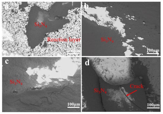
Figure 9.
Fractographies of TiZrHfNbMo HEAs/AgCuTi/Si3N4 joints brazed at different temperatures. (a) 800 °C, (b) 820 °C, (c) 840 °C, (d) 860 °C.
4. Conclusions
Reliable connections between HEAS and Si3N4 ceramics can be realized by using AgCuTi powder filler. The interface microstructure and properties of the TiZrHfNbMo HEAS/AgCuTi/Si3N4 brazed joint were studied. The main conclusions are as follows:
(1) The brazed joint of TiZrHfNbMo HEAs/Si3N4 ceramics with brazing temperature of 800 °C, 820 °C, 840 °C and 860 °C are well connected, and there are no obvious defects on the joint interface. The typical interface microstructure of the TiZrHfNbMo HEAs/AgCuTi/Si3N4 brazed joint is HEAs/TiCu(Hf,Zr)NbMo + Cu4Ti/Ag(s, s), Cu(s, s), CuTi/CuTi + Ti5Si3/Si3N4. TiCu(Hf,Zr)NbMo phase is formed between AgCuTi filler and TiZrHfNbMo HEAS.
(2) With the increase of brazing temperature, the diffusion rate between filler and base metal increases, which leads to the increase of the thickness of Cu4Ti + TiCuHfNbMo and TiN + Ti5Si3 reaction layer between filler and high-entropy alloy.
(3) When the brazing temperature is 800 °C, 820 °C, 840 °C and 860 °C, the shear strength of the joint is 30 MPa, 72 MPa, 86 MPa and 21 MPa, respectively.
Author Contributions
Conceptualization, X.W. and T.M.; methodology, X.W., K.S. and L.L.; formal analysis, D.Z.; investigation, X.W. and D.D.; resources, D.Z. and D.D.; data curation, X.W. and P.H.; writing—original draft preparation, X.W. and P.H.; writing—review and editing, D.Z., X.Y. and D.D. All authors have read and agreed to the published version of the manuscript.
Funding
This work was supported by the National Natural Science Foundation of China [No. 52071165] and the Zhejiang Province Natural Science Foundation of China (Grant No.: LQ20E010003).
Institutional Review Board Statement
Not applicable.
Informed Consent Statement
Not applicable.
Data Availability Statement
All data, models, and code generated or used during the study appear in the submitted article.
Conflicts of Interest
The authors declare no conflict of interest.
References
- Dada, M.; Popoola, P.; Mathe, N.; Pityana, S.; Adeosun, S.; Aramide, O. The comparative study of the microstructural and corrosion behaviour of laser-deposited high entropy alloys. J. Alloy. Compd. 2021, 866, 158777. [Google Scholar] [CrossRef]
- Mukarram, M.; Mujahid, M.; Yaqoob, K. Design and development of CoCrFeNiTa eutectic high entropy alloys. J. Mater. Res. Technol. 2021, 10, 1243–1249. [Google Scholar] [CrossRef]
- Sharma, P.; Dwivedi, V.K.; Dwivedi, S.P. Development of high entropy alloys: A review. Mater. Today: Proc. 2021, 43, 502–509. [Google Scholar]
- Guo, N.; Wang, L.; Luo, L.; Li, X.; Su, Y.; Guo, J.; Fu, H. Microstructure and mechanical properties of refractory MoNbHfZrTi high-entropy alloy. Mater. Des. 2015, 81, 87–94. [Google Scholar] [CrossRef]
- Shen, H.; Zhang, J.; Hu, J.; Zhang, J.; Mao, Y.; Xiao, H.; Zhou, X.; Zu, X. A Novel TiZrHfMoNb High-Entropy Alloy for Solar Thermal Energy Storage. Nanomaterials 2019, 9, 248. [Google Scholar] [CrossRef]
- Song, W.; Wang, S.; Lu, Y.; Zhang, X.; Xia, Z. Friction behavior of PTFE-coated Si3N4/TiC ceramics fabricated by spray technique under dry friction. Ceram. Int. 2021, 47, 7487–7496. [Google Scholar] [CrossRef]
- Luo, S.C.; Guo, W.M.; Plucknett, K.; Lin, H.T. Improved toughness of spark-plasma-sintered Si3N4 ceramics by adding HfB2. Ceram. Int. 2021, 47, 8717–8721. [Google Scholar] [CrossRef]
- Pazhouhanfar, Y.; Delbari, S.A.; Asl, M.S.; Shaddel, S.; Pazhouhanfar, M.; Van Le, Q.; Shokouhimehr, M.; Mohammadi, M.; Namini, A.S. Characterization of spark plasma sintered TiC– Si3N4 ceramics. Int. J. Refract. Met. Hard Mater. 2021, 95, 105444. [Google Scholar] [CrossRef]
- Zhang, P.; Hu, P.; Zhang, X.; Han, J.; Meng, S. Processing and characterization of ZrB2–SiCW ultra-high temperature ceramics. J. Alloy. Compd. 2009, 472, 358–362. [Google Scholar] [CrossRef]
- Hu, P.; Wang, Z. Flexural strength and fracture behavior of ZrB2–SiC ultra-high temperature ceramic composites at 1800 °C. J. Eur. Ceram. Soc. 2010, 30, 1021–1026. [Google Scholar] [CrossRef]
- Sun, Y.; Zhang, J.; Geng, Y.P.; Ikeuchi, K.; Shibayanagi, T. Microstructure andmechanical properties of an Si3N4/ Si3N4 joint brazed with Au–Ni–Pd–V filler nalloy. Scr. Mater. 2011, 64, 414–417. [Google Scholar] [CrossRef]
- Kim, M.D.; Wahid, M.F.; Raju, K.; Kim, S.; Yu, J.H.; Park, C.D.; Yoon, D.H. Efficacy of Ag-CuO Filler Tape for the Reactive Air Brazing of Ceramic-Metal Joints. J. Korean Ceram. Soc. 2018, 55, 492–497. [Google Scholar] [CrossRef]
- Lemus-Ruiz, J.; León-Patiño, C.A.; Aguilar-Reyes, E.A. Interface behavior during the self-joining of Si3N4 using a Nb-foil interlayer. Scr. Mater. 2006, 54, 1339–1343. [Google Scholar] [CrossRef]
- Aydin, M. The Joinging of Porous Ceramic Materials with Stainless Steel Using Diffusion Welding Method. J. Fac. Eng. Archit. GaZi Univ. 2008, 23, 595–599. [Google Scholar]
- Lan, L.; Ren, Z.; Yu, J.; Yang, Z.; Zhong, Y. Microstructure and mechanical properties of partial transient liquid phase bonded Si3N4–DZ483 superalloy joints. Mater. Lett. 2014, 121, 223–226. [Google Scholar] [CrossRef]
- Weyrich, N.; Leinenbach, C. Low temperature TLP bonding of Al2O3–ceramics using eutectic Au–(Ge, Si) alloys. J. Mater. Sci. 2013, 48, 7115–7124. [Google Scholar] [CrossRef]
- Li, W.-Q.; Hu, S.-P.; Lei, Y.-Z.; Song, X.-G.; Feng, J.-C. Interfacial microstructure and mechanical properties of GH99 superalloy and Nb brazed joint using Cu75Pt25 filler. Trans. Nonferrous Met. Soc. China 2020, 30, 2724–2736. [Google Scholar] [CrossRef]
- Guo, W.; Hou, J.; Wan, M.; Fu, L.; Lin, T.; He, P. Microstructural evolution, mechanical properties, and FEM analysis of the residual stress of sapphire joints brazed with a novel borate glass. Ceram. Int. 2021, 47, 6699–6710. [Google Scholar] [CrossRef]
- Li, H.; Shen, W.; Wang, W.; Liu, G.; Lu, C.; Zheng, W.; Ma, Y.; Yang, J.; Ding, Z.; Zou, H.; et al. Microstructural evolution and mechanical properties of AlCoCrFeNi high-entropy alloy joints brazed using a novel Ni-based filler. J. Alloy. Compd. 2020, 860, 157926. [Google Scholar] [CrossRef]
- Huang, C.; Zhang, Y.; Shen, J.; Vilar, R. Thermal stability and oxidation resistance of laser clad TiVCrAlSi high entropy alloy coatings on Ti–6Al–4V alloy. Surf. Coat. Technol. 2011, 206, 1389–1395. [Google Scholar] [CrossRef]
- Zhao, Y.; Wang, M.; Cao, J.; Song, X.; Tang, D.; Feng, J. Brazing TC4 alloy to Si3N4 ceramic using nano-Si3N4 reinforced AgCu composite filler. Mater. Des. 2015, 76, 40–46. [Google Scholar] [CrossRef]
- Liu, Y.; Wang, G.; Cao, W.; Xu, H.; Huang, Z.; Zhu, D.; Tan, C. Brazing ZrB2 -SiC ceramics to Ti6Al4V alloy with TiCu-based amorphous filler. J. Manuf. Process 2017, 30, 516–522. [Google Scholar] [CrossRef]
- Song, X.; Zhao, Y.; Hu, S.; Cao, J.; Fu, W.; Feng, J. Wetting of AgCu-Ti filler on porous Si3N4 ceramic and brazing of the ceramic to TiAl alloy. Ceram. Int. 2018, 44, 4622–4629. [Google Scholar] [CrossRef]
- Zhao, Y.; Song, X.; Tan, C.; Hu, S.; Cao, J.; Feng, J. Microstructural evolution of Si3N4/Ti6Al4V joints brazed with nano-Si3N4 reinforced AgCuTi composite filler. Vacuum 2017, 142, 58–65. [Google Scholar] [CrossRef]
- Ong, F.S.; Tobe, H.; Sato, E. Intermetallics evolution and fracture behavior of Nb interlayer inserted Si3N4/Ti joints brazed with AgCuTi filler. Mater. Sci. Eng. A 2019, 762. [Google Scholar] [CrossRef]
- Guo, W.; Zhang, H.; Ma, K.; Zhu, Y.; Zhang, H.; Qi, B.; Li, F.; Peng, P. Reactive brazing of silicon nitride to Invar alloy using Ni foam and AgCuTi intermediate layers. Ceram. Int. 2019, 45, 13979–13987. [Google Scholar] [CrossRef]
- Li, X.; Wang, H.; Wang, T.; Zhang, B.; Yu, T.; Li, R. Microstructural evolution mechanisms of Ti600 and Ni-25%Si joint brazed with Ti-Zr-Ni-Cu amorphous filler foil. J. Mater. Process. Technol. 2017, 240, 414–419. [Google Scholar] [CrossRef]
- Dong, D.; Xu, H.; Zhu, D.; Wang, G.; He, Q.; Lin, J. Microstructure and mechanical properties of TiC/Ti matrix composites and Ti–48Al–2Cr–2Nb alloy joints brazed with Ti–28Ni eutectic filler alloy. Arch. Civ. Mech. Eng. 2019, 19, 1259–1267. [Google Scholar] [CrossRef]
- Wang, W.; Liu, Y.; Wang, G.; Tan, C.; Cao, W. Vacuum brazing ZSC(f) composite ceramics to TC4 alloy with Ag-Cu filler. J. Mater. Res. Technol. 2020, 9, 8627–8635. [Google Scholar] [CrossRef]
- Zhou, X.; Liu, Z.; Li, Y.; Li, Y.; Li, P.; Huang, F.; Ding, S.; Lee, J.; Du, S.; Huang, Q. SiC ceramics joined with an in-situ reaction gradient layer of TiC/Ti3SiC2 and interface stress distribution simulations. Ceram. Int. 2018, 44, 15785–15794. [Google Scholar] [CrossRef]
- Yang, H.; Zhou, X.; Shi, W.; Wang, J.; Li, P.; Chen, F.; Deng, Q.; Lee, J.; Han, Y.-H.; Huang, F.; et al. Thickness-dependent phase evolution and bonding strength of SiC ceramics joints with active Ti interlayer. J. Eur. Ceram. Soc. 2017, 37, 1233–1241. [Google Scholar] [CrossRef]
- Gotman, I.; Gutmanas, E.Y.; Mogilevsky, P. Interaction between SiC and Ti powder. J. Mater Res. 1993, 8, 2725–2733. [Google Scholar] [CrossRef]
- Tian, X.Y.; Feng, J.C.; Shi, J.M.; Li, H.W.; Zhang, L.X. Brazing of ZrB2-SiC-C ceramic and GH99 superalloy to form reticular seam with low residual stress. Ceram. Int. 2015, 41, 145–153. [Google Scholar] [CrossRef]
Publisher’s Note: MDPI stays neutral with regard to jurisdictional claims in published maps and institutional affiliations. |
© 2021 by the authors. Licensee MDPI, Basel, Switzerland. This article is an open access article distributed under the terms and conditions of the Creative Commons Attribution (CC BY) license (https://creativecommons.org/licenses/by/4.0/).