1. Introduction
The ease with which a metal can be machined by cutting is described as machinability and is one of the key factors affecting its utility for a certain product. Depending on the application, machinability may be seen in terms of productivity, tool wear rate, total power consumption, attainable surface finish, etc., all affecting production costs or desired properties of the final product. Aluminum alloys are generally considered to have good machinability compared to ferrous alloys. However, their ductility and tendency to form very long stringy chips, which build-up at the cutting tool edge, are responsible for poor surface finish, high machining forces and lower productivity. Aluminum alloys that are particularly suitable for machining with the highly productive automatic CNC cutting machines are the so-called free-cutting or free-machining aluminum alloys. The most important free-cutting aluminum alloys came from the 2xxx and 6xxx series with additions of lead or combinations of lead, bismuth, and tin. Due to the toxicity of lead, international directives (ELV, RoHS) [
1,
2] were passed in the European Union from 1 July 2008, which limit the use of lead in aluminum alloys to a maximum of 0.4 wt.%. In recent years, even stricter measures have been imposed (RoHS 3 Pb < 0.1 wt.%), forcing manufacturers to develop new free-cutting aluminum alloys without the addition of lead.
To improve the machinability of aluminum alloys, specific alloying elements are added which form small, homogeneously dispersed low melting point inclusions in the aluminum matrix. During cutting, the heat generated by frictional forces increases the temperature in the cutting zone to such an extent that these inclusions melt and cause a local loss of strength in the material, resulting in lower cutting forces, easier breaking of the chips and those preventing their build-up at the cutting tool.
This improves smoothness of the machined surface, prolong tool life, enables higher tool feeds, and spindle speeds and thus the productivity. Intentionally produced inclusions, which are formed in the aluminum matrix by the addition of specific alloying elements, must have much lower melting point and hardness compared to aluminum matrix. Alloying elements, suitable for such propose, must not form high melting point intermetallic phases with aluminum or other alloying elements and must be practically insoluble in aluminum matrix. According to these criteria, lead, tin, bismuth, cadmium, antimony, indium, sodium, potassium and mercury can be considered as potential alloying elements. Although that machinability can be improved by a whole range of elements, in practice lead, tin, and bismuth are used most commonly. Other elements are not suitable for economic reasons (indium), corrosion sensitivity (sodium, potassium) or toxicity (cadmium, mercury). Several researchers were looking for a suitable additional element that could replace lead in the 2xxx and 6xxx series [
3,
4,
5]. Koch et al. investigated the influence of tin on machinability of the 2xxx series and concluded that tin has a favorable influence on machinability if its concentration in the alloy is sufficient, but on the other hand increase the propensity to cracking during hot processing (rolling, extruding) [
6,
7]. Faltus et. al. investigated the influence of the combination of tin and bismuth addition on the structure and properties of 6xxx lead-free alloys and found that the key factor for machinability and ductility is the amount and type of particles that these two elements form. At higher Mg content and lower Si/Mg ratio, a higher amount of Mg
2Sn and Mg
3Bi
2 phase particles is formed, which reduce the ductility and machinability of the alloy, while at higher Si/Mg ratio and lower Mg content, a higher amount of low melting point eutectics is formed, which improve machinability [
8].
The aim of this research was to investigate whether the melt preparation route affects the solidification sequence of the Pb-free aluminum alloy AA6026 with 1.1 wt.% bismuth addition and thus has an influence on the machinability of the alloy. All experiments were designed to simulate variable industrial conditions. Detailed thermodynamic analyses and microstructural characterization was performed to explain the solidification sequence and microstructure development.
2. Materials and Methods
Figure 1 shows the scheme of melt preparation methods of AA 6026 alloy with an addition of 1.1 wt.% Bi. The chemical composition of the alloy before the addition of bismuth is shown in
Table 1. In all melt preparation methods, the alloy was melted in an induction furnace (Induktio, Induktio d.o.o, Ljubljana, Slovenia) in a graphite crucible, hold for various times at 720 °C in an electrical resistant heating furnace (Bosio, Bosio d.o.o., Celje, Slovenia) and cast into a croning sand mold which ensures a cooling rate of ≈ 300 °C/min [
9]. Exactly 7 min before each casting, 0.02 wt.% of AlTi3B1 grain refiner in the form of wire was added into the melt. The main difference between melt preparation methods was when the bismuth had been added in the melt.
In the first method, bismuth was added to the melt in the induction melting furnace and melted for another 30 min, transferred to the holding furnace, and cast after different holding times. In the second method, bismuth was added to the melt during transfer into the holding furnace and cast after different holding times, and in the third method together with the grain refiner AlTi3B1 in the holding furnace exactly 7 min before casting. In all cases, the holding times at 720 °C were 60 min, 105 min, and 150 min.
The reason for selection of such casting parameters was to simulate the manufacturing process of the alloy in an industrial environment, where the casting of a batch of 20 to 25 tons, which takes from 1 to 1.5 h, is carried out after induction melting and a minimum 60 min holding time for degassing, slag removal, etc. in electrical resistance furnace.
Bismuth content was determined with ARL 4460 OES Thermo Scientific spectrometer (Thermo Fisher Scientific, Waltham, USA), and microstructure analyzed with optical microscope Zeiss Axio Observer7 (Zeiss, Oberkochen, Germany), scanning electron microscope Jeol JSM 5610 (JEOL, Tokyo, Japan) equipped by EDS detector Gresham Scientific Instruments Ltd., Model Sirius 10/SUTW (High Wycombe, England), and PANalytical X’Pert PRO 3040 (PANalytical B.V., Almelo, Netherlands), using DataCollector software for data acquisition and HighScorePlus for data analysis. Solidification was monitored with differential scanning calorimetry Netzsch STA 449C Jupiter (NETZSCH-Gerätebau GmbH, Selb, Germany and Thermo-Calc software (Thermo-Calc, Stockholm, Sweden).
3. Results and Discussions
3.1. Bismuth Content in Castings
The results of the bismuth content measurements are shown in
Table 2. The samples are labeled according to the melt preparation method (first digit) and holding time in minutes (last number). A slightly lower bismuth concentration was detected when bismuth was added together with grain refiner (third method), but the differences are practically negligible.
3.2. Determination of Crystal Grain Size in Accordance with ASTM E-112-96 Standard
Because solidification rate significantly affects the size of the crystal grains and therefore the mechanical properties, one of our priorities was also achieving comparable solidification rates between laboratory and industrial cast alloys. In general, it is known that under industrial conditions, the grain size class ASTM (G) from 1.5 to 5 can be achieved.
The crystal grain size class was determined according to the ASTM E-112-96 standard by the line cross-section method (
Figure 2). The average grain size class of the laboratory castings was (G) 3, with an average grain size of 120.3 μm and an average number of 62 crystal grains per mm
2.
3.3. Calculation of Isopleth Phase Diagram of AA6026 Alloy with 1.1 wt.% Bismuth with Themo-Calc Software
Using the Thermo-Calc software, an equilibrium isopleth diagram (
Figure 3,
Table 3) and nonequilibrium Scheil–Gulliver diagram were drawn for the investigated AA6026 alloy with 1.1 wt.% bismuth. The diagrams helped us to determine the individual microstructural phases and to compare the equilibrium and nonequilibrium states with the actual solidification sequence of the alloy. It should be noted that the calculation of those diagrams with the Thermo-Calc software is based on thermodynamic laws, a TCAL6 database with experimentally determined parameters, and the assumption of an equilibrium solidification.
The isopleth equilibrium diagram shows that solidification of the primary α-Al phase begins at 648 °C, followed by solidification of the heterogeneous structure (α-Al + Al15Si2(FeMn)3) at 631 °C. The calculation of Thermo-Calc predicts a monotectic liquid separation at 615 °C. The melt then solidifies according to two separate systems. Aluminum-rich melt solidifies at 568 °C, followed by precipitation of Mg2Si, βSi, Al13Cr4Si4, Al9Fe2Si2, and Al5Cu2Mg8Si6 phases, while bismuth-rich melt solidifies as binary eutectic (α-Al–Bi) at 271 °C. The calculated magnesium solubility in the bismuth-rich melt at the liquid separation temperature is about 0.35 wt.% and initially increases slightly with decreasing temperature (up to 0.5 wt.% at 568 °C), followed by a gradual decrease with decreasing temperature to a practically negligible content at 271 °C.
However, the calculations of isopleth equilibrium diagram as well as Scheil–Gulliver nonequilibrium diagram did not predict the formation of the intermetallic α-Mg3Bi2 phase, which was confirmed by XRD and microstructural analysis (SEM-EDS). Since there was no significant difference between the equilibrium and nonequilibrium calculations, only the equilibrium diagram is presented.
3.4. XRD and Microstructural Analysis
XRD (
Figure 4) and SEM analysis (
Figure 5) showed that the same phases (α-Al, Al
15Si
2(FeMn)
3, Mg
2Si, and Mg
3Bi
2) are present in the microstructure regardless of the melt preparation method used. For the XRD analysis the PANalytical, X’Pert PRO instrument was used, equipped with Empyrean X-ray tube and Cu Kα target, without the monochromator (Kα
a X-rays: 0.15418 nm). The amount of all other phases that might have existed were below the detection limit of the XRD method (≈3 vol.%).
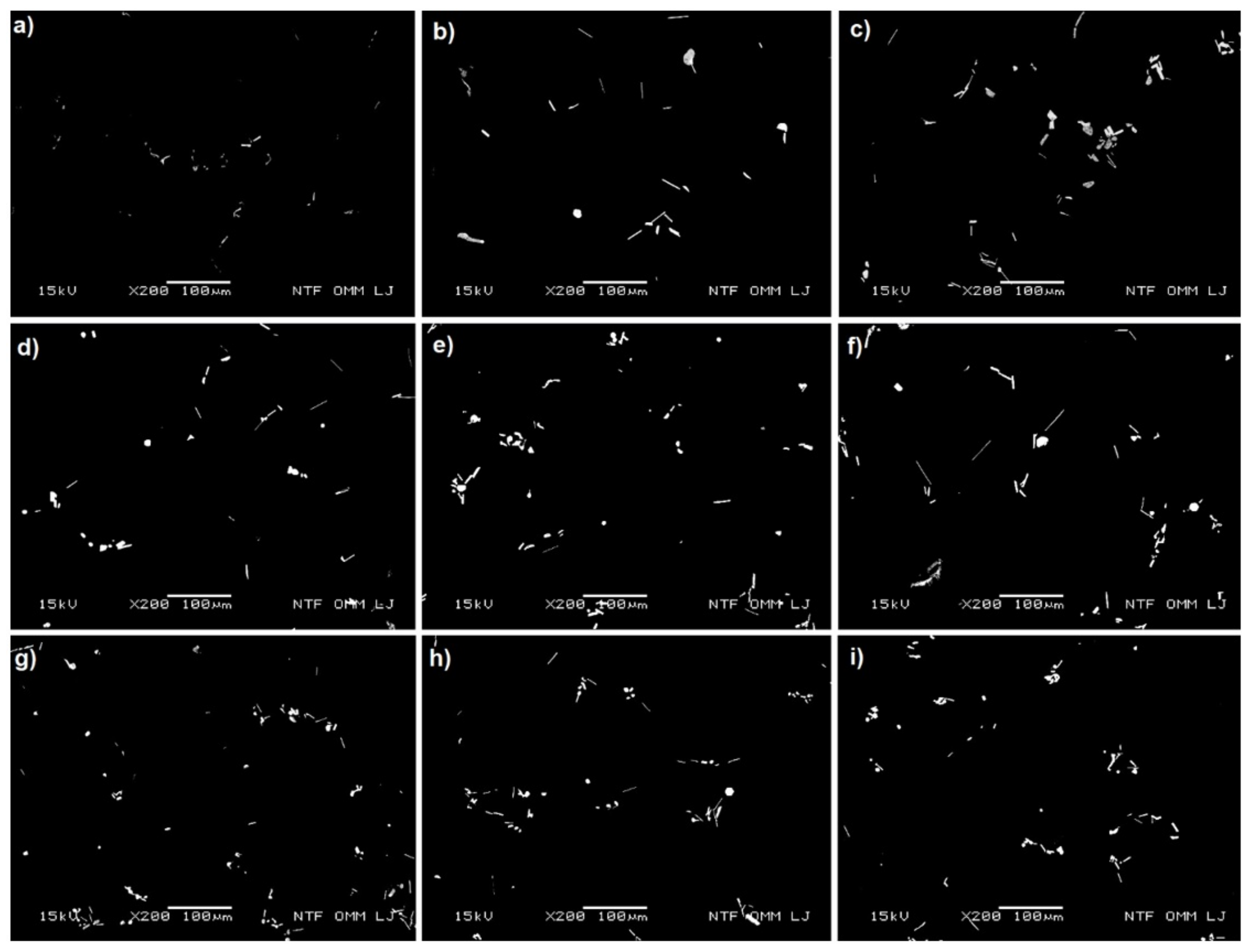
The intermetallic Mg
3Bi
2 phases were found along the α-Al grain boundaries (plate shaped) and within the α-Al grains (angular, spherical and hexagonal particles) as shown in
Figure 5 and
Figure 6. The differences between the melt preparation methods are visible in the size of the Mg
3Bi
2 phase particles and their distribution. The smallest amount of all Mg
3Bi
2 phases was detected in samples prepared by the first method with the shortest holding time at 720 °C (Bi added in induction furnace, 1M60). On the other hand, plate-shaped Mg
3Bi
2 particles were the longest when the first method with the longest holding time was applied (1M150). The melt preparation method had also an influence on the amount and size of Mg
3Bi
2 angular and hexagonal shaped particles inside the α-Al grains. The most frequently and the largest were formed when the second method with the longest holding time was applied (bismuth added before holding, 2M150). Particle clustering also increased with longer holding time for both methods. Samples cast by the third method showed a similar microstructure as samples made by the second method, with the difference that all Mg
3Bi
2 phase particles were smaller. As expected, holding time had no visible effect on Mg
3Bi
2 phase particles in samples prepared by third method.
3.5. Solidification Model of AA6026 Alloy with 1,1 wt.% Bi Addition
Under the equilibrium conditions, aluminum and bismuth formed a monotectic binary system (
Figure 7a), with the monotectic point at 657.7 °C and 3.4 wt.% Bi. In hypomonotectic composition range components form a homogenous melt (L) above T
mon, whereas in the hypermonotectic composition range (>3.4 wt.% Bi), the components form a single liquid phase (L) only above the temperature T
bin. When cooled below this temperature, the melt (L) decomposes into two mutually immiscible melts: L → L
1-Bi rich + L
2-Al rich with a large difference in density. In this so-called liquid two-phase zone, Bi-rich melt droplets (L
1-Bi rich) nucleate and grow by diffusion in an Al-rich melt (L
2-Al rich) until a monotectic temperature T
mon is reached (657.7 °C), and monotectic reaction occurs: L
2-Al rich → α-Al + L
1-Bi rich. Upon further cooling, the Bi-rich melt solidifies according to the eutectic reaction: L
1-Bi rich → α-Al + Bi at 271 °C [
10,
11]. Due to a wide temperature range between monotectic and terminal eutectic reaction, Bi-rich melt droplets are susceptible to ripening, clustering, spheroidization, and enrichment with alloying elements or impurity elements in the alloy. In pure Al-Bi hypomonotectic alloys the morphology of Bi particles depends on temperature gradients and solidification velocities [
12]. If solidification velocity is between 0.3 m/s and 6 m/s and large gradients are imposed, Bi fibers are expected to occur, while at higher solidification rates, pearl (droplet) type particles form.
According to the Al-Bi system, the alloy under investigation had a hypomonotectic composition. However, since pure bismuth was added to the melt at 720 °C in the form of small particles (5-20 mm3) the melt became hypermonotectic in the vicinity of the melting bismuth particles and decompose into two immiscible melts. Since the droplets require some time to decompose in the surrounding molten aluminum melt by convection currents, magnesium may accumulate to the amount favourable for β-Mg3Bi2 phase formation.
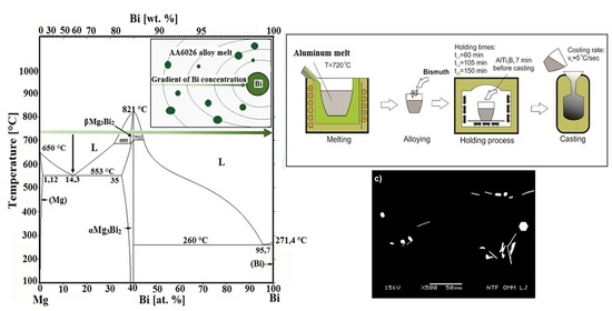
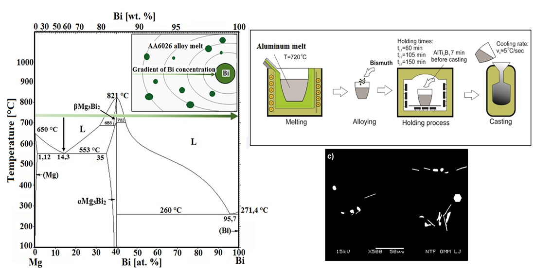
According to the Mg-Bi binary system (
Figure 7b), the Mg
3Bi
2 phase exist in two temperature-controlled modifications: above 703 °C as β-Mg
3Bi
2 with atomic ratio Mg/Bi = 1.5 and melting point 821 °C, and at room temperature as α-Mg
3Bi
2, with a hexagonal anti-La
2O
3 type structure (space group of P3m1) [
13]. At 720 °C two-phase region L + β-Mg
3Bi
2 exists at an atomic Mg/Bi ratio between ≈1.22 and ≈1.86, which expands with decreasing temperature. If a β-Mg
3Bi
2 nucleus is formed in magnesium enriched bismuth droplet, it becomes stable, even if Bi-rich melt droplet decomposes completely, because β-Mg
3Bi
2 has higher melting point than surrounding aluminum melt. This is consistent with observations, that samples prepared by the first method (bismuth addition in induction furnace) have lower amount of angular and hexagonal Mg
3Bi
2 particles inside α-Al crystal grains regardless holding time, due to higher temperature and inductive stirring of the melt and thus faster disintegration of the bismuth melt droplets. Their presence in the microstructure of the samples prepared by third method indicates rapid nucleation and growth of the β-Mg
3Bi
2 phase, while their higher amount, larger size, and clustering in the samples prepared by the second method with longer holding times indicate their stability and growth already in the aluminum melt.
According to ternary Al-Mg-Bi phase system [
14,
15] two apparently identical (L
1-Bi rich + L
2-Al rich + α-Mg
3Bi
2) tree-phase equilibria exist (
Figure 8). One in the bismuth corner and the other in aluminum corner. Bismuth-rich melt can start to solidify in dependence of Mg enrichment, as (α-Al + α-Mg
3Bi
2) or as (Bi + α-Mg
3Bi
2), while aluminum-rich melt will before (α-Al + Al
15Si
2(FeMn)
3), and precipitation of other phases, also undergo binary eutectic reaction (α-Al + α-Mg
3Bi
2). Since Mg
3Bi
2 phase occurred in microstructure at various locations, surrounded by different microstructure constituents, we assumed that the hexagonal and angular particles inside α-Al crystal grains have been formed as primary β-Mg
3Bi
2 phase which were engulfed by α-Al solidification front, plate-shaped particles as (α-Al + α-Mg
3Bi
2) from Al-rich melt, and spherical particles as (Bi + α-Mg
3Bi
2) divorced eutectic form Bi-rich melt.
To prove that Bi-rich melt can be enriched with magnesium, we performed an experiment in which the melt (2M60) had been solidified in a copper mold at a high cooling rate (≈700 °C/s) (
Figure 9a).
Figure 9b shows the microstructure of the rapidly solidified sample. Mg-Bi phases with high Mg content (>45 at.%) are clearly visible, indicating high susceptibility of Bi-rich melt to Mg enrichment.
3.6. Results of Differential Scanning Calorimetry
The detailed thermodynamic analyses (DSC) have been performed on samples 1M60, 2M105, and 3M60. Heating curves up to 880 °C, i.e., above the melting point of the β-Mg
3Bi
2 phase T
m = 821 °C [
13,
17] and cooling curves were recorded. The heating and cooling rates in all experiments were 10 °C/min.
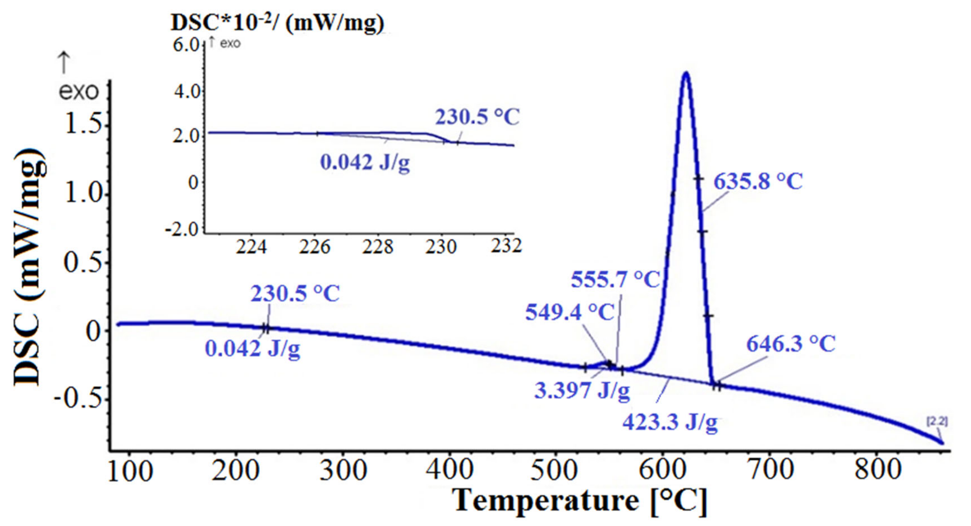
3.6.1. DSC Heating Curves
The DSC heating curve (
Figure 10) shows a small exothermic peak in the temperature range between 225.6 °C and 420.2 °C, which can be attributed to complex sequential precipitation of the transition and Mg
2Si phases or reformation of binary eutectic (Bi + α-Mg
3Bi
2). The first endothermic peak was visible in the temperature range between 537.7 °C and 576.6 °C, indicating melting of the Mg
2Si phase. The largest endothermic peak corresponds to melting of the (α-Al + α-Mg
3Bi
2), (α-Al + Al
15Si
2(FeMn)
3) and α-Al solid solution. Further, a small endothermic deviation on the curve could be seen at 799.7 °C, which indicates the presumed dissolution of the primary β-Mg
3Bi
2 phase. The DCS heating curves of the other two samples (2M105, 3M60) showed a similar pattern, with distinctive endothermic deviations at 797.2 °C and 783.7 °C.
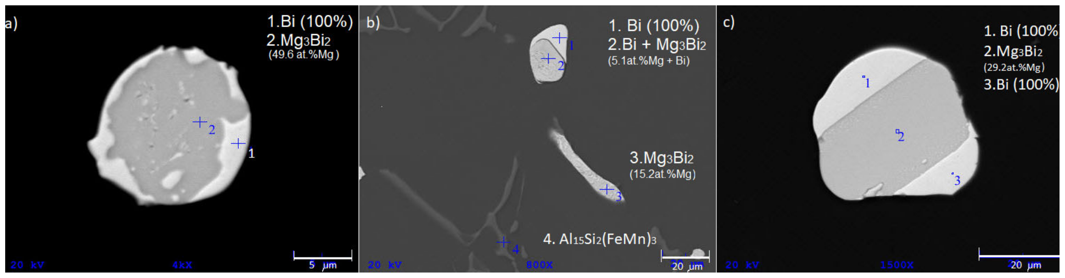
3.6.2. DSC Cooling Curves
The cooling DSC curve is shown in
Figure 11. The first exothermic peak corresponded to the solidification of the primary α-Al phase and the solidification of the heterogeneous structures (α-Al + Al
15Si
2(FeMn)
3) and (α-Al + α-Mg
3Bi
2). The second exothermic peak indicated the precipitation of the Mg
2Si phase. The solidification ended with the formation of a low melting point divorced eutectic (Bi + α-Mg
3Bi
2) at 230.5 °C, which was also confirmed by the microstructural analyses shown in
Figure 12. Namely, α-Mg
3Bi
2 phase plate-shaped particles, rounded divorced eutectic structures (α-Mg
3Bi
2 + Bi), with high Mg content, and spherical particles with practically stoichiometric eutectic composition were found in the microstructure. Interestingly, no such divorced eutectic was observed in the microstructure of cast samples, regardless of the melt preparation method used. According to the equilibrium Mg–Bi phase diagram (
Figure 7b) the eutectic (Bi + α-Mg
3Bi
2) forms at 260 °C (4.3 at.% Mg), whereas in DSC remelted samples bismuth droplets solidified as divorced eutectic with hypoeutectic composition (Mg-Bi system) or as primary Bi phase and Mg-Bi eutectic with equilibrium composition (hypereutectic composition in Mg-Bi system). The cooling curves of the other two samples showed a similar DSC pattern and microstructure with a slight temperature shift of the exothermic peaks. With DSC analyses we did not detect solidification of the primary β-Mg
3Bi
2 phase during cooling, neither its melting during repeated heating of DSC samples.
The absence of angular and hexagonal Mg3Bi2 phase particles in the microstructure of DCS remelted samples can be attributed to high overheating of the melt during DSC analysis (880 °C), above the melting point of β-Mg3Bi2 phase. Even though the β-Mg3Bi2 existed, it melted, and aluminum melt started to solidify according to the Al-Bi system as a single hypomonotectic melt.
4. Conclusions
Bismuth was added to an aluminum AA6026 alloy as a replacement for the lead which is commonly used for improving the machinability. The isopleth equilibrium diagram and Scheil–Gulliver nonequilibrium diagram predicted that bismuth would solidify at the temperature 271 °C in elementary form. However, in all casted samples the same phases were present (α-Al, Al15Si2(FeMn)3, Mg2Si, and Mg3Bi2) in the microstructure regardless of the melt preparation method used. Bismuth interacted with magnesium and formed Mg3Bi2 phase, which was not predicted with Thermo-Calc software. Therefore, the mechanism of the intermetallic Mg3Bi2 phase formation was studied.
Based on the microstructure and thermodynamic analysis a solidification model of AA6026 + 1.1 wt.% Bi was proposed. The model explains the development of the microstructure and the formation of individual microstructural constituents, in particular the intermetallic α-Mg
3Bi
2 phase, which is known to reduce machinability [
3,
4,
6,
8] and increase the cracking tendency during hot working [
8].
Bismuth reacts with magnesium and forms the intermetallic α-Mg3Bi2 phase, which can occur as angular or hexagonal particles inside α-Al crystal grains, as high melting point heterogeneous structure (α-Al + α-Mg3Bi2), in the form of plates and spherical particles on the α-Al grain boundaries or as low melting point eutectic (Bi + α-Mg3Bi2) with hypo- or hypereutectic composition. If bismuth is added in elemental form at temperatures below melting point of β-Mg3Bi2 (821 °C), small amount of primary β-Mg3Bi2 phase particles can form already in the melt due to melt separation and enrichment of the Bi melt droplets with magnesium, but the majority of α-Mg3Bi2 phase forms as high melting point eutectic after monotectic reaction from magnesium enriched bismuth droplets.
Only eutectics with a low melting point (Bi-Mg3Bi2, Tm < 260 °C) can improve machinability, as they melt due to the heat generated during cutting, promote the braking of long stringy chips and prevent their build-up on the tool cutting edge.
Melt preparation methods used in this research will to some extent influence the distribution of Mg
3Bi
2 phase particles but will not entirely prevent the formation of high melting point eutectic (α-Al + α-Mg
3Bi
2), which reduce the ductility and machinability of the alloy [
8]. Namely, due to Marangoni effect, enrichment of the Bi droplets is extremely fast.
The addition of bismuth alone does not have such an effect on machinability as the addition of lead, and cannot be an equivalent substitute, as it forms a higher melting point eutectic with magnesium than magnesium with silicon, and those reduce the amount of precipitation hardening Mg2Si phase.
Author Contributions
Conceptualization, A.N., S.R., M.B. and P.C.; methodology, S.R. and A.N.; validation, S.R., A.N., J.M., and B.K.; investigation, S.R., A.N., J.M. and B.K.; resources, P.C. and M.B.; data curation, S.R., A.N. and B.K.; writing—original draft preparation, S.R., A.N. and B.K.; writing—review and editing, A.N., B.K., J.M., M.B. and P.C.; visualization, S.R., B.K., J.M. and M.B.; Supervision, A.N. and M.B.; project administration, M.B. and P.C.; funding acquisition, P.C., M.B. and A.N. All authors have read and agreed to the published version of the manuscript.
Funding
This research received no external funding.
Acknowledgments
The authors would like to thank Anton Smolej for his assistance and helpful discussions. This paper is part of research work within the national Research Programs Nr. P1-0195 financed by the Slovene Ministry of Education, Science and Sport and supported by Impol d.o.o. through the project entitled “Development of aluminum free-cutting alloys”. The authors are very grateful for the financial support.
Conflicts of Interest
The authors declare no conflict of interests.
References
- Official Journal of the European Union. Directive 2002/95/EC of the European Parliament and of the Council of 27th January 2003 on the Restriction of the Use of Certain Hazardous Substances in Electrical and Electronic Equipment; Artesyn Technologies, Inc.: Boca Raton, FL, USA, 2005. [Google Scholar]
- Official Journal of the European Union. Directive 2000/53/EG of the European Parliament and of the Council of 18th September 2000 on End-of Life Vehicles (ELV). Off. J. Eur. Union 2020, 269, 34–43. [Google Scholar]
- Adhikari, S.; Giri, A.; Raman, V.S.; Koparde, P.; Gupta, S.; Vijayaraghavan, L.; Sankaran, S. Investigations on Pb-Free 6000 Series Aluminum Alloy for Machining Applications; The Minerals, Metals & Materials Series; Springer: Berlin/Heidelberg, Germany, 2018; pp. 285–292. [Google Scholar] [CrossRef]
- Timelli, G.; Bonollo, F. Influence of tin and bismuth on machinability of lead free 6000 series aluminium alloys. Mater. Sci. Technol. 2011, 27, 291–299. [Google Scholar] [CrossRef]
- Koch, S.; Antrekowitsch, H. Effects of varied Sn and Cu content in lead-free Al-Cu based alloys intended for free machining. In Proceedings of the Conference of Metallurgists COM 2010, Vancouver, BC, Canada, 3–6 October 2010; pp. 289–298. [Google Scholar]
- Koch, S.; Antrekowitsch, H. Investigations of lead-free aluminium alloys for machining. World Metall. 2010, 64, 26–30. [Google Scholar]
- Koch, S.; Antrekowitsch, H. Free-Cutting Aluminium Alloys with Tin as Substitution for lead. Berg. Hüttenmännische Mon. 2008, 153, 278–281. [Google Scholar] [CrossRef]
- Faltus, J.; Karlík, M.; Haušild, P. Influence of the chemical composition on the structure and properties of lead-free machinable AA 6023 (Al-Mg-Si-Sn-Bi) alloy. In Proceedings of the 13th International Conference on Aluminum Alloys (ICAA13): TMS (The Minerals, Metals & Materials Society), Pittsburgh, PA, USA, 3–7 June 2012; pp. 1545–1550. [Google Scholar] [CrossRef]
- Vončina, M.; Mrvar, P.; Medved, J. Thermodynamic analysis of AlSi10Mg Alloy. RMZ Mater. Geoenviron. 2006, 52, 621–633. [Google Scholar]
- Schaffer, L.P.; Mathiesen, H.R.; Arnbergl, L.; Di Sabatino, M.; Snigirev, A. In situ investigation of spinodal decomposition in hypermonotectic Al–Bi and Al–Bi–Zn alloys. New J. Phys. 2008, 10, 053001. [Google Scholar] [CrossRef]
- Paliwal, M.; Jung, I. Thermodynamic modeling of the Al_Bi, Al_Sb, Mg_Al_Bi and Mg_Al_Sb systems. CALPHAD Comput. Coupling Phase Diagr. Thermochem. 2010, 34, 51–63. [Google Scholar] [CrossRef]
- Silva, A.P.; Spinelli, J.E.; Garcia, A. Microstructural evolution during upward and downward transient directional solidification of hypomonotectic and monotectic Al–Bi alloys. J. Alloys Compd. 2009, 480, 485–493. [Google Scholar] [CrossRef]
- Kayadibi, F.; Günay, S.D.; Taseven, Ç. Studying Static, Dynamic and Transport Properties of Mg3Bi2. Acta Phys. Pol. A 2015, 128, 440–446. [Google Scholar] [CrossRef]
- Raghavan, V. Al-Bi-Mg (Aluminum-Bismuth-Magnesium). J. Phase Equilibria Diffus. 2011, 32, 448–450. [Google Scholar] [CrossRef]
- Chunju, N.; Changrong, L. Assessment of the Al-Bi-Mg system and extrapolation to the Al-Bi-Mg-Sn quaternary system. Calphad 2018, 60, 37–49. [Google Scholar] [CrossRef]
- Nayeb-Hashemi, A.A.; Clark, J. The Bi-Mg (Bismuth-Magnesium) System. Bull. Alloy Phase Diagr. 1985, 6, 1985. [Google Scholar] [CrossRef]
- Guangyin, Y.; Yangshan, S.; Wenjiang, D. Effects of bismuth and antimony additions on the microstructure and mechanical properties of AZ91 magnesium alloy. Mater. Sci. Eng. 2001, 308, 38–44. [Google Scholar] [CrossRef]
Figure 1.
Schematic presentation of laboratory melt preparation routes.
Figure 1.
Schematic presentation of laboratory melt preparation routes.
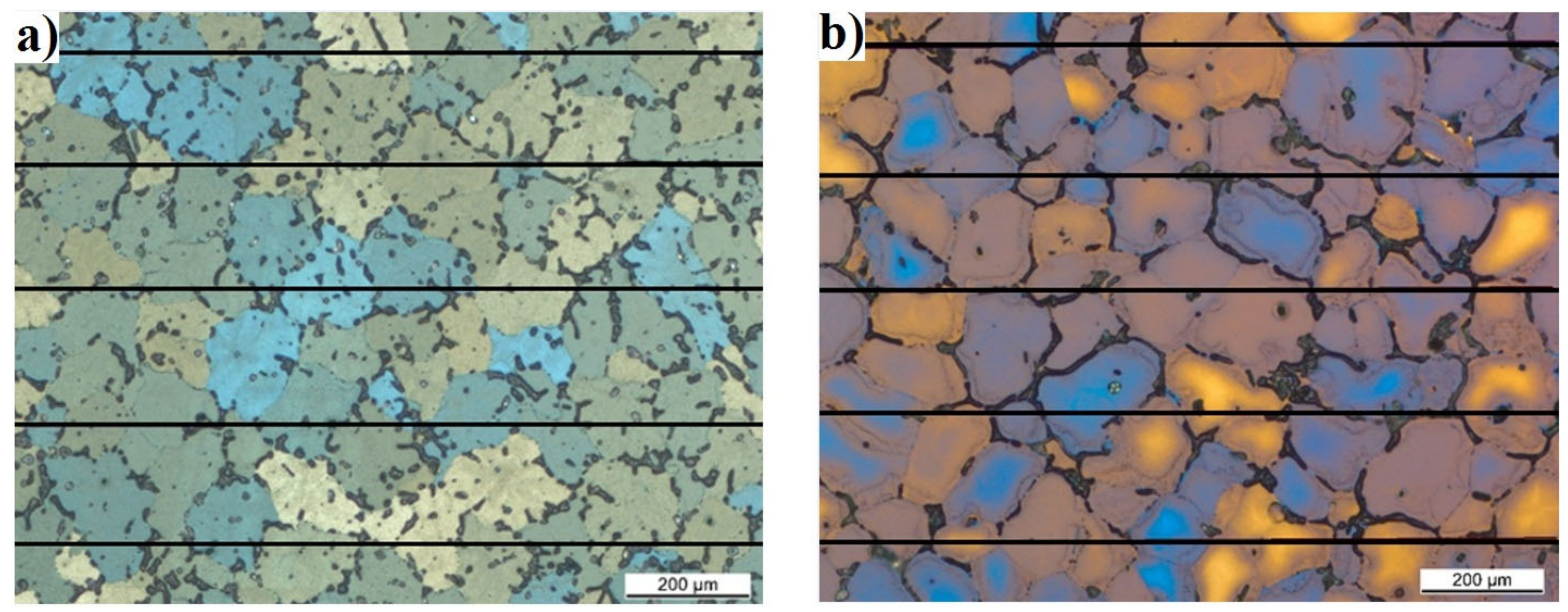
Figure 2.
Microstructure of AA6026 with 1.1 wt.% Bi (a) industrially cast, (b) laboratory cast (electrolytically etched with Barker’s reagent).
Figure 2.
Microstructure of AA6026 with 1.1 wt.% Bi (a) industrially cast, (b) laboratory cast (electrolytically etched with Barker’s reagent).
Figure 3.
Isopleth phase diagram of 6026 alloy with 1.1 wt.% Bi (Thermo-Calc calculation).
Figure 3.
Isopleth phase diagram of 6026 alloy with 1.1 wt.% Bi (Thermo-Calc calculation).
Figure 4.
XRD diffraction pattern of AA6026 alloy (sample 3M105, other samples had similar diffraction patterns).
Figure 4.
XRD diffraction pattern of AA6026 alloy (sample 3M105, other samples had similar diffraction patterns).
Figure 5.
Microstructure of the samples (BEI). Mg3Bi2 phases (bright areas) (a) 1M60, (b) 1M105, (c) 1M150, (d) 2M60, (e) 2M105, (f) 2M150, (g) 3M60, (h) 3M105, and (i) 3M150.
Figure 5.
Microstructure of the samples (BEI). Mg3Bi2 phases (bright areas) (a) 1M60, (b) 1M105, (c) 1M150, (d) 2M60, (e) 2M105, (f) 2M150, (g) 3M60, (h) 3M105, and (i) 3M150.
Figure 6.
Plate, angular, and hexagonal Mg3Bi2 phases (bright areas) (a) 1M150, (b) 2M150 (c) 3M105 (BEI-higher magnification).
Figure 6.
Plate, angular, and hexagonal Mg3Bi2 phases (bright areas) (a) 1M150, (b) 2M150 (c) 3M105 (BEI-higher magnification).
Figure 7.
Phase diagrams: (
a) Al-Bi [
10]; (
b) Mg-Bi (modified from ref. [
16]).
Figure 7.
Phase diagrams: (
a) Al-Bi [
10]; (
b) Mg-Bi (modified from ref. [
16]).
Figure 8.
Al-Mg-Bi ternary phase diagram [
15].
Figure 8.
Al-Mg-Bi ternary phase diagram [
15].
Figure 9.
(a) Copper mold design; (b) Microstructure of the sample cast in copper mold (SEM).
Figure 9.
(a) Copper mold design; (b) Microstructure of the sample cast in copper mold (SEM).
Figure 10.
Detailed thermodynamic analysis (DSC) heating curve (sample 1M60, heating rate 10 °C/min).
Figure 10.
Detailed thermodynamic analysis (DSC) heating curve (sample 1M60, heating rate 10 °C/min).
Figure 11.
DSC cooling curve (sample 1M60, cooling rate 10 °C/min).
Figure 11.
DSC cooling curve (sample 1M60, cooling rate 10 °C/min).
Figure 12.
Micrographs of low-melting eutectic (Mg3Bi2 + Bi) types in DSC remelted samples. (a) divorced eutectic (hypoeutectic composition Mg-Bi), (b) eutectic droplet (hypereutectic composition) and plate (hypoeutectic composition Mg-Bi), (c) hypoeutectic lamellar structure.
Figure 12.
Micrographs of low-melting eutectic (Mg3Bi2 + Bi) types in DSC remelted samples. (a) divorced eutectic (hypoeutectic composition Mg-Bi), (b) eutectic droplet (hypereutectic composition) and plate (hypoeutectic composition Mg-Bi), (c) hypoeutectic lamellar structure.
Table 1.
Chemical composition of the alloy.
Table 1.
Chemical composition of the alloy.
| Element | Si | Fe | Cu | Mn | Mg | Al |
|---|
| wt.% | 1.13 | 0.19 | 0.32 | 0.75 | 0.74 | Bal. |
Table 2.
Bismuth content in wt.%.
Table 2.
Bismuth content in wt.%.
| Sample | 1M60 | 1M105 | 1M150 | 2M60 | 2M105 | 2M150 | 3M60 | 3M105 | 3M150 |
|---|
| Bismuth content | 1.13 | 1.14 | 1.12 | 1.15 | 1.11 | 1.13 | 1.09 | 1.10 | 1.07 |
Table 3.
Calculated phases with the Thermo-Calc software.
Table 3.
Calculated phases with the Thermo-Calc software.
| LIQUID = Al-melt (homogenous) | DIAMOND_A4 = βSi |
| LIQUID#2 = Bi-rich melt | AL13CRSI4 = Al13Cr4Si4 |
| FCC_A1 = α-Al | AL9FE2SI2 = Al9Fe2Si2 |
| AL15SI2M4 = Al15Si2(FeMn)3 | Q_ALCUMGSI = Al5Cu2Mg8Si6 |
| MG2SI_C1 = Mg2Si | RHOMBO_A7 = Bi |
| Publisher’s Note: MDPI stays neutral with regard to jurisdictional claims in published maps and institutional affiliations. |
© 2021 by the authors. Licensee MDPI, Basel, Switzerland. This article is an open access article distributed under the terms and conditions of the Creative Commons Attribution (CC BY) license (https://creativecommons.org/licenses/by/4.0/).


