1. Introduction
The metastable defects whose configuration depends on bias and/or thermal treatments, and whose behavior was not always easily or fully understood, have a special place in studying the deep-level defects in semiconductors. One of those bi-stable defects is the M-center in 4H-SiC material, reported for the first time almost two decades ago [
1]. Since then, M-center has been observed upon the low energy electron irradiation [
2,
3], 2.5 MeV proton irradiation [
1,
4,
5,
6] and 2 MeV He ion implantation [
7] of n-type 4H-SiC. Comprehensive experimental studies and analyses have been performed using mostly the deep-level transient spectroscopy (DLTS).
The M-center in n-type 4H-SiC is a bi-stable defect whose configuration depends on bias and thermal treatments imposed on the samples. Therefore, by adjusting the bias and following well-defined annealing procedures [
7], M-center can be placed in a selected configuration before DLTS measurement. It has been widely accepted among the research community to refer to the M-center configurations as A and B.
Since the first published reports of the M-center, three deep-level defects were assigned to it. The M
1 (0.41–0.43 eV) and M
3 (0.75–0.9 eV) deep levels were observed in configuration A, while the M
2 (0.63–0.70 eV) deep level was observed in configuration B [
1,
2,
3,
4,
5,
6]. In addition to these three deep levels arising from the M-center, Nielsen et al. [
6] have proposed the existence of a fourth deep level in configuration B and labeled it as M
4. However, due to the technical limitations of DLTS, i.e., the fact that the technique itself involves a temperature scan, the M
4 deep level was not accessible for many years.
Recently, Coutinho et al. [
8] provided the direct evidence on the existence of the M
4 (0.86 eV) deep level in 4H-SiC. Combining the advanced first-principles calculations and isothermal DLTS, it was demonstrated that the properties of M-center, including bistability, annealing, reconfiguration kinetics and electronic levels, match those of the carbon self-interstitial.
In this work, we have applied DLTS, high-resolution Laplace DLTS (L-DLTS) and isothermal DLTS to study the metastable defects in 4H-SiC material introduced by epithermal and fast neutron irradiation. The main aim of this work is to investigate the much less studied neutron irradiation induced defects primarily due to the growing interest and applications of 4H-SiC materials for neutron detection [
9]. In addition, our intention is to compare these findings with the recently published study on ion implantation induced defects and to further explore the possibilities of isothermal DLTS technique.
2. Materials and Methods
For this study, we have used n-type nitrogen-doped 4H-SiC epitaxial layers, 25 µm thick. The epilayers were grown on an 8° off-cut silicon face of a 350 µm thick 4H-SiC (0001) wafer without a buffer layer. The Schottky barriers diodes (SBDs) were formed by thermal evaporation of nickel through a metal mask with a patterned square aperture of 1 mm × 1 mm, while Ohmic contacts were formed on the backside of the silicon carbide substrate by nickel sintering at 950 °C in an Ar atmosphere.
The SBDs were irradiated with epithermal and fast neutrons at the Jozef Stefan Institute (JSI) TRIGA reactor in Ljubljana, Slovenia. The selected neutron fluence was 10
13 cm
−2. Thermal neutrons with energy less than 0.55 eV were filtered by irradiating the Schottky barrier diodes inside a cadmium box with a wall thickness of 1 mm. The neutron energy spectrum and irradiation settings are the same as in the previously reported study [
10].
Figure 1 displays the neutron spectra in the pneumatic tube (PT) irradiation channel, located in the F-24 core position, obtained by Monte Carlo simulation using the MCNP code and subsequently characterized based on experimental neutron activation measurements. More details are given elsewhere [
10].
The temperature-dependent current-voltage (I-V-T) and capacitance-voltage (C-V-T) measurements were performed by a Keithley 4200 SCS (Keithley Instruments, Cleveland, OH, USA). DLTS, L-DLTS and isothermal DLTS measurements were performed using a Boonton 7200 capacitance meter (Boonton Electronics, New York, NY, USA) and NI PCI-6521 data acquisition device (NI, Austin, TX, USA). Reverse bias and electrical filling pulses were applied to the SBDs using the analog output of the acquisition device. The stable temperature control of the SBD in OptistatDN cryostat (Oxford Instruments, Oxfordshire, England) was realized using Lakeshore 332 and Lakeshore 335 temperature controllers (Lake Shore Cryotronics, Inc., Westerville, OH, USA). The sample temperature was constant during isothermal DLTS measurements, changing less than 0.05 K. The isothermal DLTS technique is a very useful technique which enables studies of the deep-level transformation kinetics at the same temperature [
11].
Three different annealing procedures were used to control the configuration of the M-center prior to measurements. Detailed descriptions on annealing procedures are given elsewhere [
7].
3. Results and Discussion
Figure 2 shows the free-carrier concentration profiles of as-grown, 2 MeV He ion-implanted and epithermal and fast neutron-irradiated n-type 4H-SiC samples (solid lines, left y axis) and the calculated vacancy concentration profiles (dashed lines, right y axis). More details on 2 MeV He ion implantation are given in a previous study [
7].
The displacement damage profiles, i.e., the vacancy concentration profiles, are simulated using the SRIM code [
12] and FLUKA software [
13] for the ion-implanted and neutron-irradiated 4H-SiC, respectively. The averaged primary displacement (vacancy) generation rate (VGR) distribution, created in collision cascades of the 2.0 MeV He ions being implanted in the 4H-SiC epitaxial layer at normal incident not aligned with the crystal axis, was simulated for a total of 10,000 ions using the SRIM code. The displacement damage introduced by neutron irradiation in the 4H-SiC epitaxial layer was simulated by Fluka software. The neutron spectrum shown in
Figure 1 (blue line) was used to select the neutron energies used in the simulation (627 values in the range 2 × 10
−4–2 × 10
7 eV) and to calculate the average displacement generation rate. A total of 106 incident neutrons were simulated for each energy. More details on simulations using SRIM code and FLUKA software are given elsewhere [
10].
As expected, the free carrier concentration profiles are significantly different in ion-implanted and neutron-irradiated samples. The reason is that epithermal and fast neutron irradiation introduces damage homogenously through the volume, while the ion implantation introduces damage with a well-defined depth profile (
Figure 2). To avoid the 2 MeV He ion projected range at 4.8 µm, a reverse voltage of −4 V corresponding to a depletion width of <4 µm was selected for DLTS measurements [
7]. Such restrictions are redundant in the case of neutron-irradiated samples, where a reverse voltage up to −10 V was used.
The reasons why we have selected epithermal and fast neutrons to introduce deep-level defects in 4H-SiC material are multiple, the growing interest in neutron radiation detection based on 4H-SiC material being just one of them [
9]. Additional reasons are (i) the homogenously distributed damage through the volume (as clearly shown in
Figure 2), which is rather important for techniques such as DLTS (that scans over volume), and (ii) the fact that epithermal and fast neutron irradiation introduces the same electrically active defects as ion implantation into 4H-SiC [
10]. Those defects are known as S
1 (0.40 eV) and S
2 (0.70 eV), and are already assigned to V
Si (−3/=) and V
Si (=/−) charge state transitions of the silicon vacancy [
14], respectively.
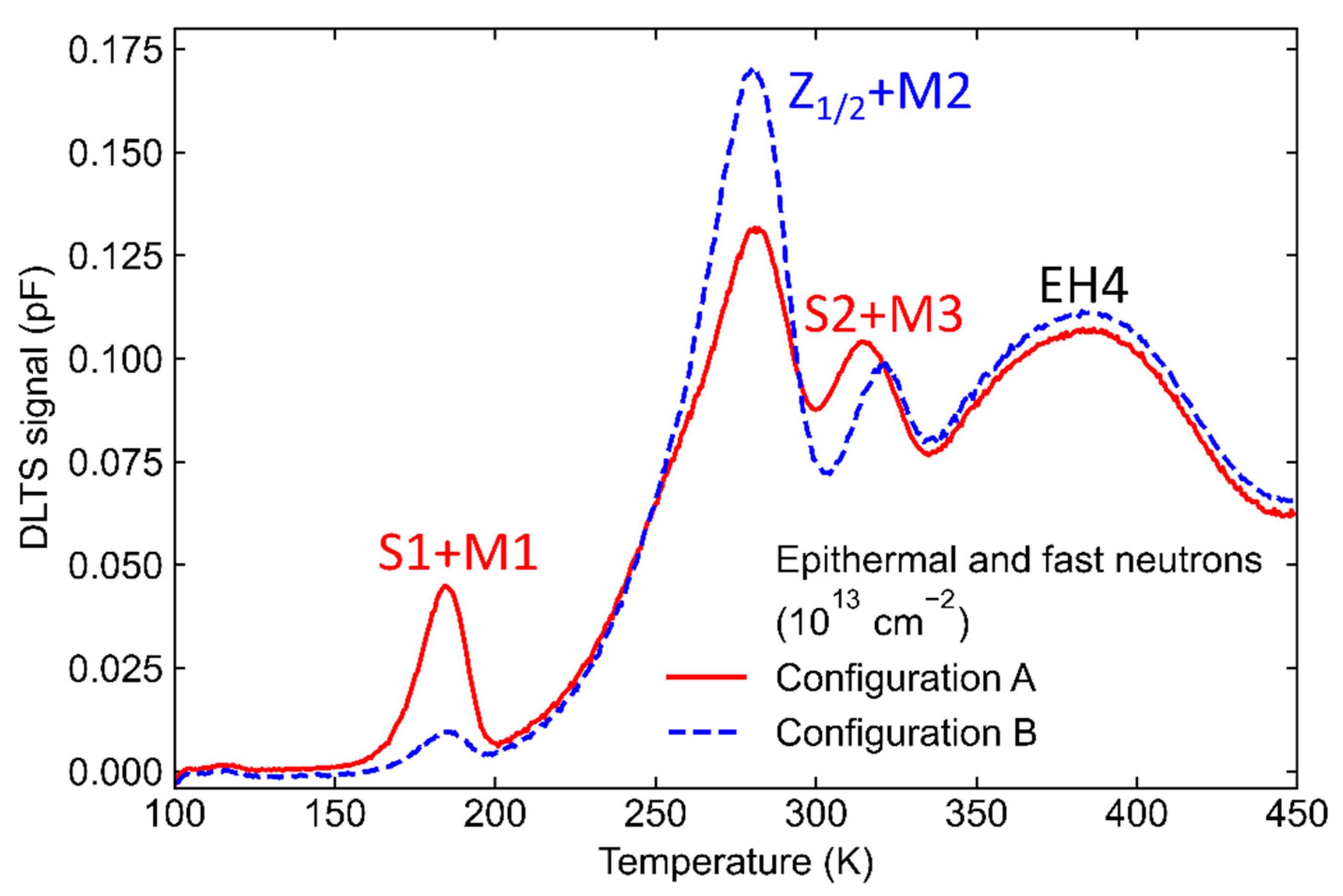
Figure 3 shows DLTS spectra for the neutron-irradiated sample in two configurations, A and B. The M-center was transformed to configuration B or configuration A by annealing at 450 K (for 20 min) and cooling down without applying bias (0 V) or by 20 min annealing at the temperature of 340 K and cooling down with the applied bias (−30 V), respectively.
In addition to a well-known Z
1/2 deep-level defect assigned to a transition between double negative and neutral charge state of carbon vacancy V
C (=/0) [
15], three deep levels with activation energies of 0.4, 0.7 and 0.9 eV below the conduction band minimum are detected. Two deep levels at 0.4 and 0.7 eV are assigned to the already-mentioned S
1 and S
2, while the 0.9 eV deep level, labeled as EH
4, is assigned to different configurations of the (−/0) charge transition of the carbon antisite-carbon vacancy (CAV) complex [
16].
The M
1 and M
3 deep levels observed in configuration A overlap with S
1 and S
2 deep levels, while the M
2 deep level observed in configuration B overlaps with Z
1/2. This result is consistent with previously published DLTS results on 2 MeV He ion implantation-induced defects [
7].
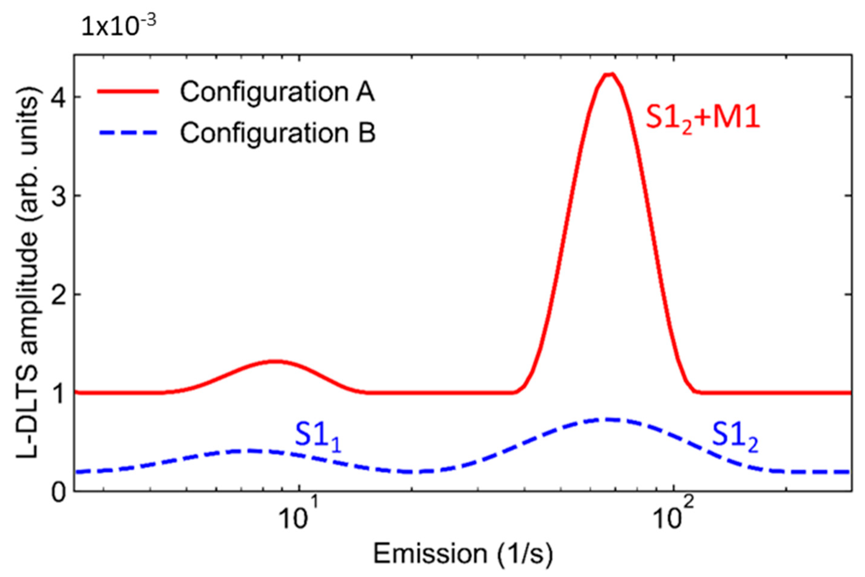
To obtain more information about the metastable defects in neutron-irradiated samples, we have applied L-DLTS to investigate S
1 and M
1 deep-level defects.
Figure 4 shows L-DLTS spectra for neutron-irradiated sample measured in configurations A and B. While keeping the sample in configuration B (only S
1 deep level is detected), two emission lines arising from S
1 are observed. The S1 Laplace emission line splitting has already been reported [
14]. The situation has slightly changed as we have set the sample in configuration A. As expected, (see
Figure 3), the signal due to the M
1 deep level is rising, and it overlaps with one of the S
1 Laplace emission lines (
Figure 4). To the best of our knowledge, this is the first time a metastable defect in 4H-SiC has been observed by L-DLTS.
According to the modeling studies [
8], the M
1 deep level is assigned to the carbon self-interstitial (Ci) residing on the hexagonal lattice site (-
h). If the S
1 emission lines splitting (S1
1 and S1
2 in
Figure 4) corresponds to silicon vacancies (V
Si) residing on two different lattice sites, such as the carbon vacancy (V
c) [
17], then we can assign two observed L-DLTS emission lines S1
1 and S1
2 to V
Si residing on two lattices sites, cubic (
-k) and hexagonal (-
h), respectively, while the M
1 deep level resides on the hexagonal (
-h) lattice site.
To compare the M
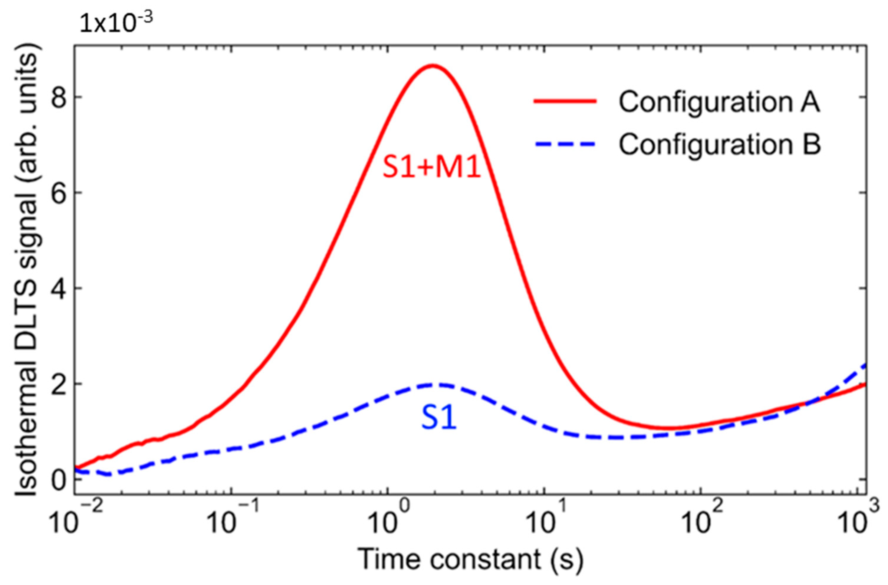
1 deep level in the 2 MeV He ion implanted with epithermal and fast neutron-irradiated 4H-SiC in more detail, the isothermal DLTS has been applied.
Figure 5 shows isothermal DLTS signals measured in configurations A and B. M-center was first placed in configuration B by annealing without bias at 450 K for 20 min, which was followed by cooling down without bias and a 20 min long waiting period at a measurement temperature. Next, M-center was placed in configuration A by applying reverse bias (−30 V) at a temperature of 340 K (for 20 min) and cooling down under reverse bias (−30 V) to the measurement temperature. The overlap of S1 and M1 is observed in configuration A, while the signal in configuration B is only due to the S1 deep level.
To get a “clean” signal coming only from the metastable defects, we have used the difference isothermal DLTS signal. The difference isothermal DLTS signal is obtained by subtracting isothermal DLTS spectra measured with M-center in configuration A and configuration B (
Figure 5). Such representation enables more accurate analysis, needed for deep-level defect parameter estimations, such as activation energy, capture cross section and concentration. More details on the analysis of isothermal DLTS data are given elsewhere [
7]. Here, we provide an additional way of presenting isothermal DLTS signal using 2D plots.
Figure 6 shows heatmap plots of the difference in isothermal DLTS signal for (a) neutron-irradiated (
Figure 5) and (b) ion-implanted samples (not shown here, see Ref. [
7] for more details). As seen in
Figure 6, the M
1 signal is almost identical in both cases.
The M1 deep level was studied by L-DLTS and isothermal DLTS, and the results clearly showed that M1 is indeed the same defect in both neutron-irradiated and ion-implanted samples; thus, we can move to a more complex situation, where the rest of M deep-level defects (M2, M3 and M4) overlap with Z1/2, S2 and EH4. Unfortunately, due to the several closely spaced deep levels, L-DLTS cannot provide additional and accurate information. Therefore, we will focus on isothermal DLTS.
Figure 7a shows isothermal DLTS spectra of neutron-irradiated sample with the M-center placed in configuration A and configuration B. The M
2 and M
4 deep levels observed in configuration B overlap with Z
1/2 and EH
4 deep levels, while the M
3 deep level observed in configuration A overlaps with S
2 deep level. From the difference isothermal DLTS signal (
Figure 7b), we can clearly detect signals due to the M
2, M
3 and M
4 deep levels.
As seen in
Figure 7b, the existence of the M
4 deep level is once again confirmed using the isothermal DLTS. The obtained spectra match previously reported spectra in case of 2 MeV He ion implantation [
7]. Using all the above mention techniques, we have estimated activation energies for metastable defects as follows: M
1 (0.41–0.43 eV), M
2 (0.64–0.70 eV) and M
3 (~0.72 eV). The activation energy for M
4 could not be accurately estimated due to the signal broadening. There are two possible explanations for this, i.e., (i) the emission rate for M
4 is too close to the reconfiguration rate from configuration B to configuration A and (ii) neutron irradiation has introduced more damage into the material (compared to 2 MeV He ion implantation), which has introduced more stress into the material and increased the broadening of DLTS and isothermal DLTS signals [
18].
The presented results, using the neutron irradiation, are consistent with all previously obtained and reported results on metastable defects in 4H-SiC using the low electron energy irradiation, proton irradiation and ion implantation [
1,
2,
3,
4,
5,
6,
7]. Moreover, these results are consistent with the first-principal calculations of M-center [
8]. The presented data reconfirm the previously made assignment of the M center to the carbon interstitial.


