Article

Diffusion Bonding of FGH 98 and CoCrNi-Based Medium-Entropy Alloy: Microstructure Evolution and Mechanical Tests

1
State Key Laboratory of Solidification Processing, Northwestern Polytechnical University, Xi’an 710072, China
2
Shaanxi Key Laboratory of Friction Welding Technologies, Northwestern Polytechnical University, Xi’an 710072, China
3
Beijing Institute of Petrochemical Technology, Beijing 102617, China
4
Beijing Academy of Safety Engineering and Technology, Beijing 102617, China
5
AVIC Manufacturing Technology Institute, Beijing 100020, China
*
Authors to whom correspondence should be addressed.
Crystals 2021, 11(10), 1158; https://doi.org/10.3390/cryst11101158
Submission received: 31 August 2021 / Revised: 15 September 2021 / Accepted: 16 September 2021 / Published: 23 September 2021

Abstract

:
The superalloy FGH98 was successfully diffusion bonded (DB) with medium-entropy alloy (MEA) Al3Ti3(CrCoNi)94 using pure Ni as the interlayer at a temperature range of 1050–1170 °C for 1 h under 5 MPa. The microstructure and mechanical properties of joints were investigated. The diffusion bonding seam was composed of an interlayer zone (IZ) and two diffusion-affected zones (DAZ). The IZ and DAZ beside the FGH98 consisted of cubic Ni3(TiAl)-type γ′ phases due to the diffusion of Ti and Al atoms. Meanwhile, the DAZ adjacent to the MEA consisted of spherical γ′ phases. Both of the γ′ phases with different morphology kept the coherent relationship with the matrix. Moreover, increase of bonding temperature led to the morphology of interlayer γ′ phase to transform from sphere to cube. Due to the strengthening effect of a mass of γ′ phase distributed evenly in IZ and the DAZ beside the FGH98, the microhardness and Young’s modulus of these two zones were higher than that of DAZ near the MEA. The maximum shear strength of DB joint, 592 MPa, was achieved in the joint bonded by 1150 °C, which was the typical ductile fracture feature confirmed by the shear dimples.

1. Introduction

The medium-entropy alloys (MEAs), especially the MEAs with face-centered-cubic (fcc) structure are currently receiving extensive attention due to their unique composition, microstructure and superior properties, such as excellent ductility, good corrosion resistance and high radiation tolerance [1,2,3,4,5]. Among them, the ternary CoCrNi MEA with single phase exhibits excellent strength-ductility trade-off due to the twining-induced plasticity (TWIP) effect and high work hardening capability [6,7]. In order to overcome the surplus ductility and resultant insufficient strength of single phase MEAs, Y.L. Zhao et al. [8] have added the strong γ′ formers Ti and Al into the CoCrNi-based MEAs, promoting the precipitation of nano-scale Ni3(Al, Ti)-type γ′. As a result, the yield strength significantly increased without sacrifice of ductility, owing to the effect of precipitation hardening. Therefore, the superior strength-ductility combination endows the nanoparticle-reinforced CoCrNi-based MEAs great potential for engineering applications [9], especially for the structural materials with extreme requirements. As is well known, welding technology, a processing method of assembling individual parts into structural parts, is an essential link in promoting materials to practical engineering application.
Presently, many researchers have studied the bonding of high entropy alloys via various welding methods [10], such as fusion welding [11], laser welding [12], and transient liquid phase bonding [13]. The above welding methods all involve the melting of materials. However, especially for the dissimilar welding, the solidification process after welding can cause dendritic segregation, the formation of brittle intermetallic compounds, and welding cracking due to the mismatch of physical properties, which is unfavorable to the mechanical properties of joints. In contrast, solid-state diffusion bonding (DB) can effectively avoid the defects in fusion welding. Li [14] investigated the diffusion bonding of eutectic high entropy alloy AlCoCrFeNi2.1 to GH4169, and the joint with high shear test of 528 MPa was obtained. Lei [15] studied the DB of Al0.85CoCrFeNi alloy to TiAl intermetallic, and the complex multiphase was observed at the bonding interface. Du [16] and Peng [17] investigated DB of the refractory high entropy alloy Al5(TiZrHfNb)95 to Ti2AlNb and TC4, respectively. Sound joints with no defects were obtained and the shear strength of these two joints both exceeded 90% of the base materials strength. Li [18] also investigated the DB of homogeneous AlCoCrFeNi2.1 and the maximum of shear strength of joints reached 648 MPa with a ductile fracture at a temperature of 1050 °C. It can be seen that lots of research has mainly focused on the DB of high entropy alloy, whilst the diffusion bonding of MEAs has not yet been reported. Similarly, the powder metallurgy Ni-based superalloy (FGH98) is also widely used in engineering as the key component material due to its high yield strength and excellent oxidation resistance at elevated temperatures [19,20,21]. Therefore, considering the element similarity between Al3Ti3(CrCoNi)94 and FGH98 and their potential application value, the reliable joining of CoCrNi-based MEAs and FGH98 to achieve the complementary advantages of both the materials is significant for their potential practical utility. Moreover, owing to the difference of material physical properties, such as thermal expansion coefficient, the residual stress is easy to produce at the bonding interface, which will become a potential safety hazard in the subsequent service process of joints [22]. Hence, the pure metals are always used as an interlayer to release the stress, and this has become a common method in diffusion bonding of dissimilar materials [23]. The pure Ni foil is always used as the interlayer due to its excellent ductility and good compatibility with superalloy [24]. Furthermore, during the process of diffusion bonding Ni-based alloys, the Ni interlayer can be alloyed due to the diffusion of Al and Ti and conducive to the formation of γ′, which ensures the strength of joints.
In this study, the dissimilar diffusion bonding joints of FGH98 and MEA Al3Ti3(CrCoNi)94 using pure Ni as the interlayer were investigated. The typical interfacial microstructure of joints was comprehensively evaluated. The structure and composition of precipitates at interface were analyzed in detail. The mechanical properties of joints were also studied.

2. Experimental Procedure

The powder metallurgy alloy FGH98 and MEA Al3Ti3(CrCoNi)94 was selected as the parent material and the pure Ni as interlayer. The MEA was prepared as follows. Firstly, the ingots of Al3Ti3(CrCoNi)94 were produced by vacuum arc melting using high pure elements powder (>99.9 wt.%) under argon atmosphere. The ingots were remelted at least 5 times to ensure the uniformity of materials and then sucked into a copper mold (10 mm × 10 mm × 50 mm). Secondly, the as-cast sheets were homogenized at 1200 °C for 2 h to eliminate the cast defects. Thirdly, the sheet was cold-rolled along the longitudinal direction with a thickness reduction of 60%. Finally, recrystallization treatment for the rolled sheet was performed at 1150 °C for 2 min followed by aging at 800 °C for 120 min. The composition of welded materials was listed in Table 1. The microstructure of both materials was exhibited in Figure 1. The FGH98 was composed of γ matrix (Ni-based solid solution), white carbides and cubic uniformly distributed Ni3Al γ′ phases. The MEA Al3Ti3(CrCoNi)94 consisted of fcc phase and the Ni3Al-type γ′ phases precipitated in matrix, which was similar to the result of Reference [15]. Prior to bonding, the sheet was cut as 15 × 10 × 2.5 mm. The welded surfaces of both materials were ground with sandpaper, and mechanically polished. Then, the sample was acid cleaned in 2 mL HF + 2 mL HNO3 + 5 mL H2O2 + 80 mL H2O followed by being ultrasonically cleaned in an ethanol bath.
The diffusion bonding was performed in a vacuum diffusion bonding furnace. The bonding parameters and post-heat treatment are listed in Table 2. After bonding, cross-sections of the bonded joints were prepared by standard metallographic preparation method. The corrosion solution composed of 1 mL HF + 3 mL HNO3 + 5 mL H2O was used to etch the polished sample for the microstructure observation. The microstructure of bonding interface was studied by scanning electron microscope (SEM) under back-scattered electron (BSE) mode with 15 kV. The composition of bonding interface was investigated by electron probe micro-analyzer (EPMA). The lattice structure of phase at bonding interface was studied by the selected area electron diffraction (SAED). The composition of the bonding interface was detected quantitatively by high angle annular dark field-scanning transmission electron microscopy (HAADF-STEM). The specific sample for TEM was prepared by focused ion beam sectioning (FIB). The nanoindentation tester was carried out to characterize the microhardness of bonding interface. The shear test was performed using the apparatus shown in Figure 1e. The compressive shear test at ambient temperature was conducted using the universal test machine at a loading speed of 0.5 mm/min.

3. Results and Discussion

3.1. Microstructure of the Joints

Figure 2 shows the different morphology and microstructure of joints bonded at different temperature. In the interface, the joint could be approximately divided into three zones (I, II and III) based on the variation of phase morphology, shown in Figure 2a. Zone I exhibits the slightly elongated grains in which the dispersive distribution phase disappears. Zone II is the intermediate layer region, and no obvious voids were found at the interface between Zone I and II, indicating that FGH 98 was tightly connected with the interlayer. In addition, fine spherical particles precipitated in the interlayer near Zone II. Conversely, there were no evident particles in the interlayer near Zone III. At the interface between Zone II and III, due to the insufficient diffusion of atoms, a series of voids were continuously distributed along the interface. As one can notice, the morphology of the three zones (I, II and III) evolved as the bonding temperature elevated. When the temperature increased to 1100 °C (Figure 2b), the grain size of Zone I was almost unchanged compared to Figure 2a. A mass of fine spherical particles precipitated diffusely in Zone I. In addition, the original spherical particles in Zone II (shown in Figure 2a2) dramatically transformed into a cube in morphology and grew to 0.5 μm. The voids disappeared at the interface between Zone II and III. Instead of voids, tiny spherical particles precipitated at the interface between Zone II and III and gradually extended 2 μm into Zone III. As temperature further increased to 1150 °C (Figure 2c), the grains in Zone I grew evidently to 55 μm. Simultaneously, the average size of precipitations in Zone II grew up to 0.7 μm. With the temperature increased to 1170 °C, the region of spherical precipitations in Zone III gradually widened to 7 μm. As bonding temperature increased to 1170 °C, the based metals grew significantly. The cubic precipitates in Zone II grew to 2 μm.
To further comprehensively testify the composition of precipitation in Zone II, the EPMA was conducted as shown in Figure 3. The results showed that Co and Cr elements were obviously deficient while Ti, Al and Ni elements gathered, indicating that the cubic precipitations in Zone II were mainly composed of Ti, Al and Ni elements. In addition to the cubic precipitations, tiny spherical particles, distributed along the interface, were also primarily composed of Ti, Al and Ni.
In order to quantitatively analyze the composition of precipitations with different morphologies, the TEM was conducted, and the result is shown in Figure 4. Overall, these different phases located on both sides of interface were enriched in Ti, Al and Ni, and depleted in Co and Cr. In order to obtain the specific elements composition of phases with different morphologies, the spot scan for each phase was performed and the test location was marked by the yellow frame in Figure 4b,c. As with the result of spot scan shown in Table 3, in Zone II, the concentration ratio of Al, Ti and Ni was approximately 1:3, indicating that the phases at Zone II might be the Ni3(Al, Ti), viz. cubic Ni3(Al, Ti)-type γ′ phases. Similarly, the spherical phases in Zone III might be spherical γ′ phases as well.
The lattice structure of the interfacial phase was obtained via SAED and high-resolution transmission electron microscopy (HR-TEM), as shown in Figure 5. Figure 5a1 displays the SAED image of cubic precipitation, and the dark field image corresponding to the diffraction spot marked by a yellow circle is shown in Figure 5a2. The results showed that the diffraction spot of the cubic phase conformed to the fcc-type superlattice according to the diffraction spot image observed via (001) zone axis. In addition, according to the HR-TEM image of phase interface shown in Figure 5a3, the cubic phase kept a coherent relationship with the γ matrix, which was similar to the literature [22]. Simultaneously, combining the result of elements distribution, the cubic phase was ordered to be the cubic Ni3(Al, Ti)-type γ′ phase. Conditions were similar in the spherical phase. This was also the case with the ordered fcc lattice structure and was coherent with matrix shown in Figure 5b1–b3, illustrating that the spherical phase was γ′ phase.

3.2. Mechanical Properties of Joints

The micro-property of the bonding interface was studied using nanoindentation.
Figure 6 shows the microhardness and Young’s modulus across the joint bonded at 1150 °C. Overall, the microhardness of joints increased gradually when the test position passed through the interface from MEA to FGH98. The MEA with fcc structure possessed the minimum hardness (4.7 GPa). The maximum of hardness was 5.9 GPa which was located in the side of FGH98. Similar to the microhardness, the Young’s modulus also showed a gradual increased trend. The minimum of modulus was 183.2 GPa at the interface between the MEA and interlayer, and the maximum at the center of the interlayer was 210.3 GPa. The above change trend of both hardness and modulus was mainly caused by the different microstructure of the bonding interface. As shown in Figure 2c, the spherical γ′ phase precipitated at the interface between the MEA and interlayer due to the diffusion of Ti and Al atoms, which strengthen the interface compared with the single fcc MEA and increased the microhardness. In addition, the Ti and Al atoms had higher diffusion rate in Ni interlayer than that of MEA due to the sluggish diffusion effect [23]. Thus, the volume fraction of γ′ phase in the Ni interlayer was significantly higher than MEA according to Figure 2c2, increasing the microhardness and strength of the interlayer, which was conductive to the property of joints.
Figure 7 shows the effect of bonding temperature on the shear strength of joints. The shear strength of joints increased initially and then decreased as the bonding temperature increased from 1050 °C to 1170 °C. This discrepancy was primarily ascribed to the different microstructure of joints. When the bonding temperature was 1050 °C, the microvoids were not closed and still distributed along the bonding interface shown in Figure 2a, which provided the nucleation site for cracking. Therefore, the joint bonded by 1050 °C had the minimum shear strength of 335 MPa. When the temperature increased to 1100 °C, the bonding defects were eliminated and γ′ phases precipitated evenly at the interlayer. As a result, the shear strength of the joint increased obviously to 534 MPa. The maximum shear strength of the joint was 592 MPa as the temperature improved to 1150 °C. However, when the temperature reached 1170 °C, the strength of the joint decreased to 500 MPa due to the grain coarsening of parent materials. The corresponding fracture morphology of joints are displayed in Figure 7b–e. When the temperature was 1050 °C, the equiaxed tiny dimples appeared at the surface. As the temperature rose to 1100 °C, except for small dimples similar to Figure 7b, the elongated dimples paralleled with the direction of shear force. The typical shear dimples [24,25] appeared at the fracture surface, illustrating the plastic deformation of the joint. When the temperature increased to 1150 °C and 1170 °C, a mass of shear dimples located at the surface indicated that the plastic deformation occurred, and the fracture mode was ductile fracture.

4. Conclusions

In this study, the FGH98 and MEA Al3Ti3(CoCrNi)94 were bonded using Ni as the interlayer. The typical microstructure and interfacial phase of the DB joint were analyzed in detail. The effect of bonding temperature on the microstructure and mechanical properties were also evaluated. The conclusions are summarized as follows:
(1)
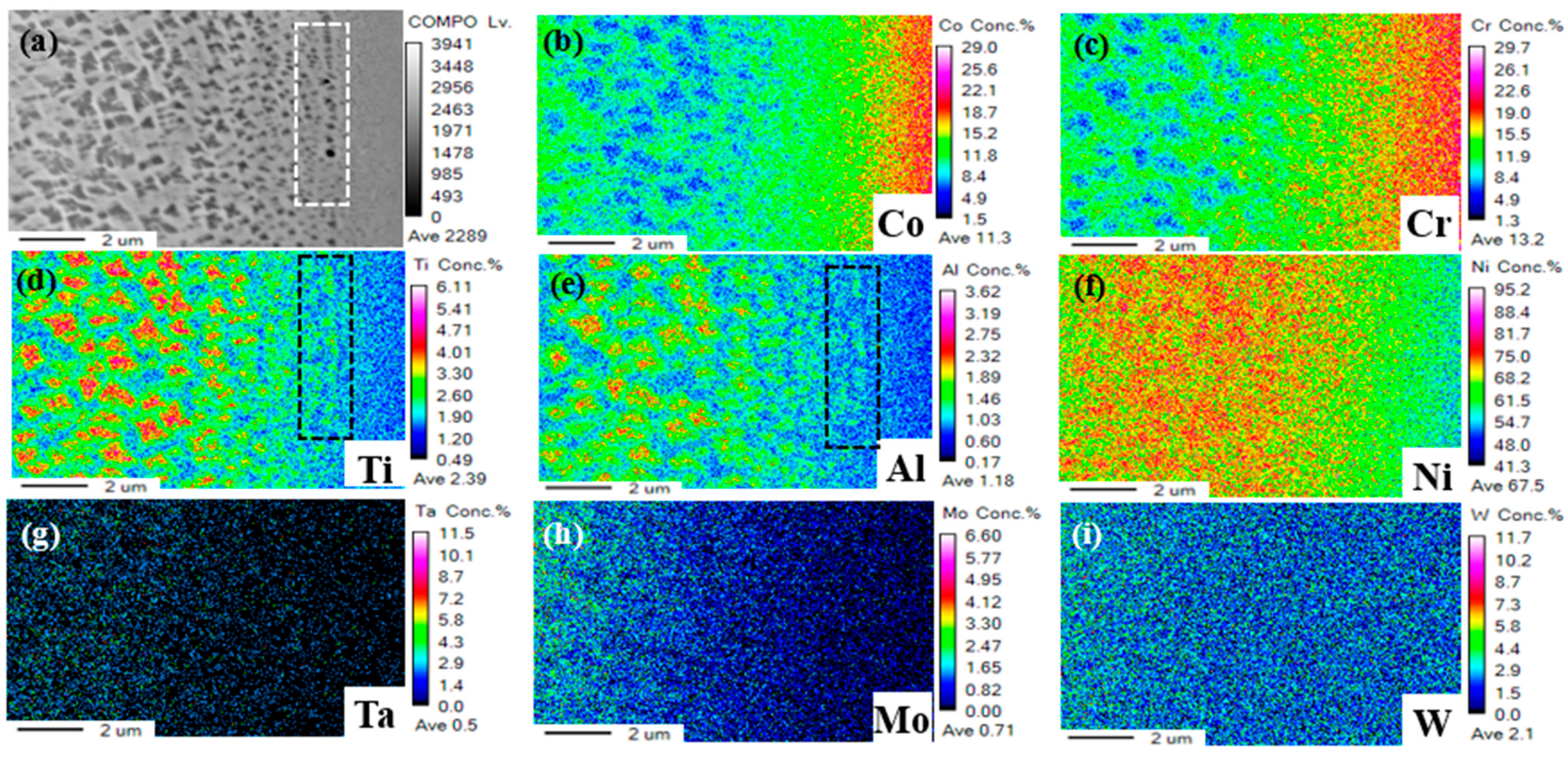
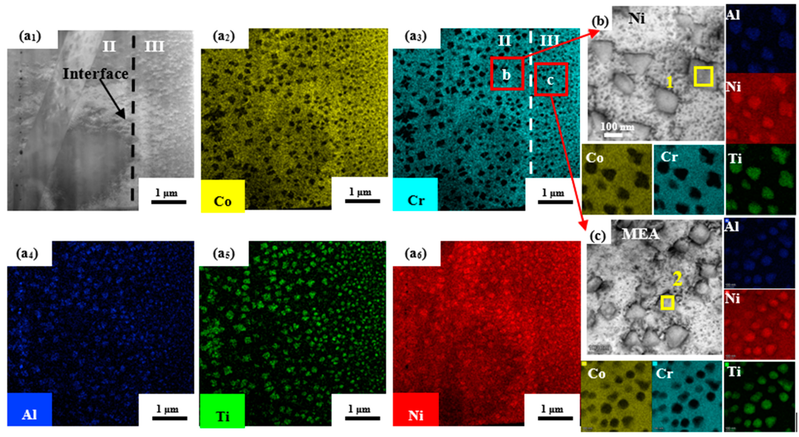
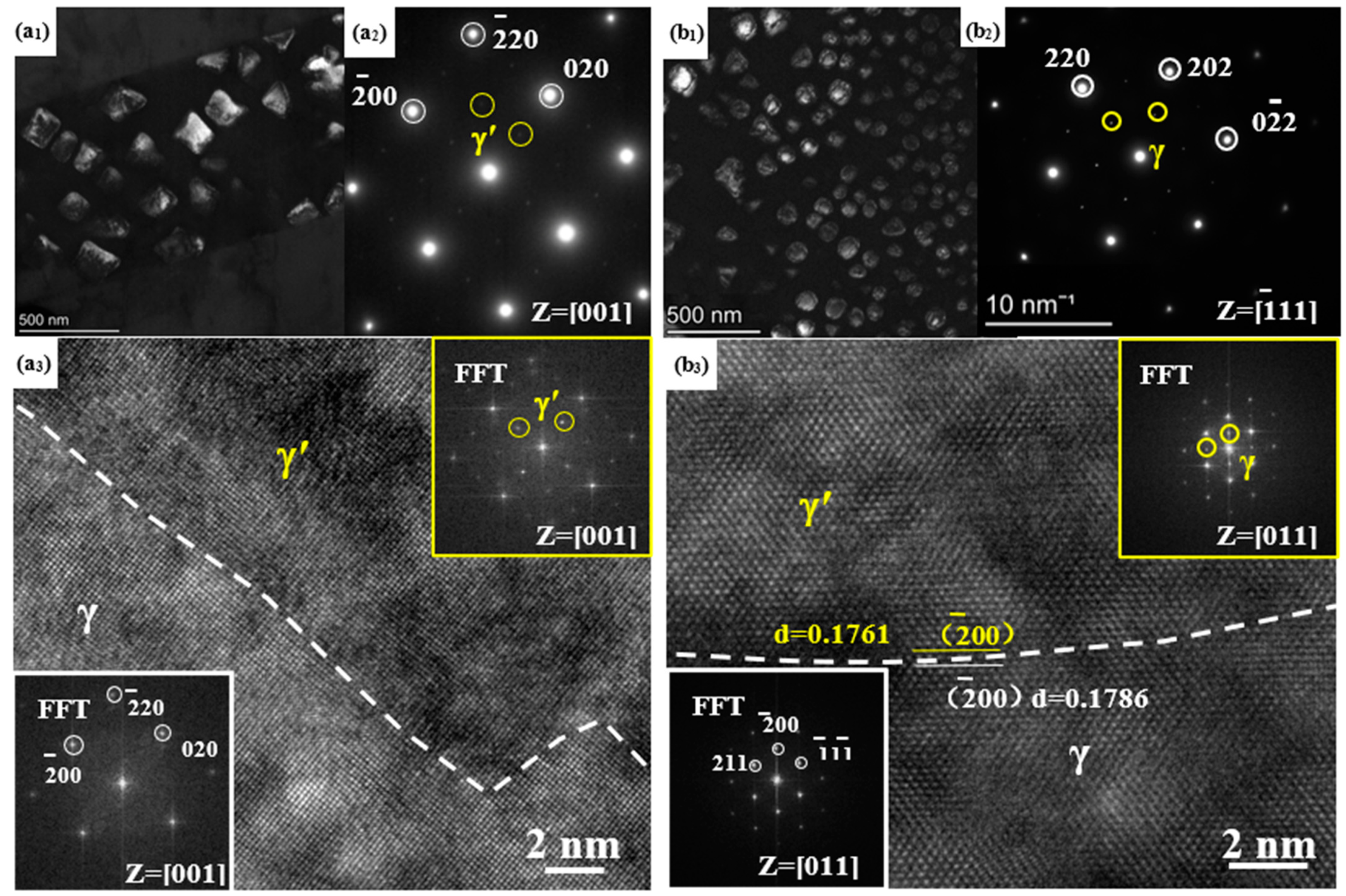
The typical microstructure of FGH98/Ni/MEA at 1150 °C-5MPa-1 h was composed of an alloyed interlayer zone and the diffusion-affected zone (DAZ). The interlayer region and diffusion-affected region adjacent to FGH98 consisted of cubical γ′ phase, and the other DAZ on the MEA was composed of spherical γ′ phase. Both of these two type γ′ phases were coherent with the matrix.
(2)
As the bonding temperature increased from 1050 to 1170 °C, the amount of γ′ phase in the interlayer increased, and the morphology of interlayer γ′ phase evolved gradually from sphere to cube. The width of DAZ adjacent to MEA also increased to 7 μm when the bonding temperature was 1170 °C.
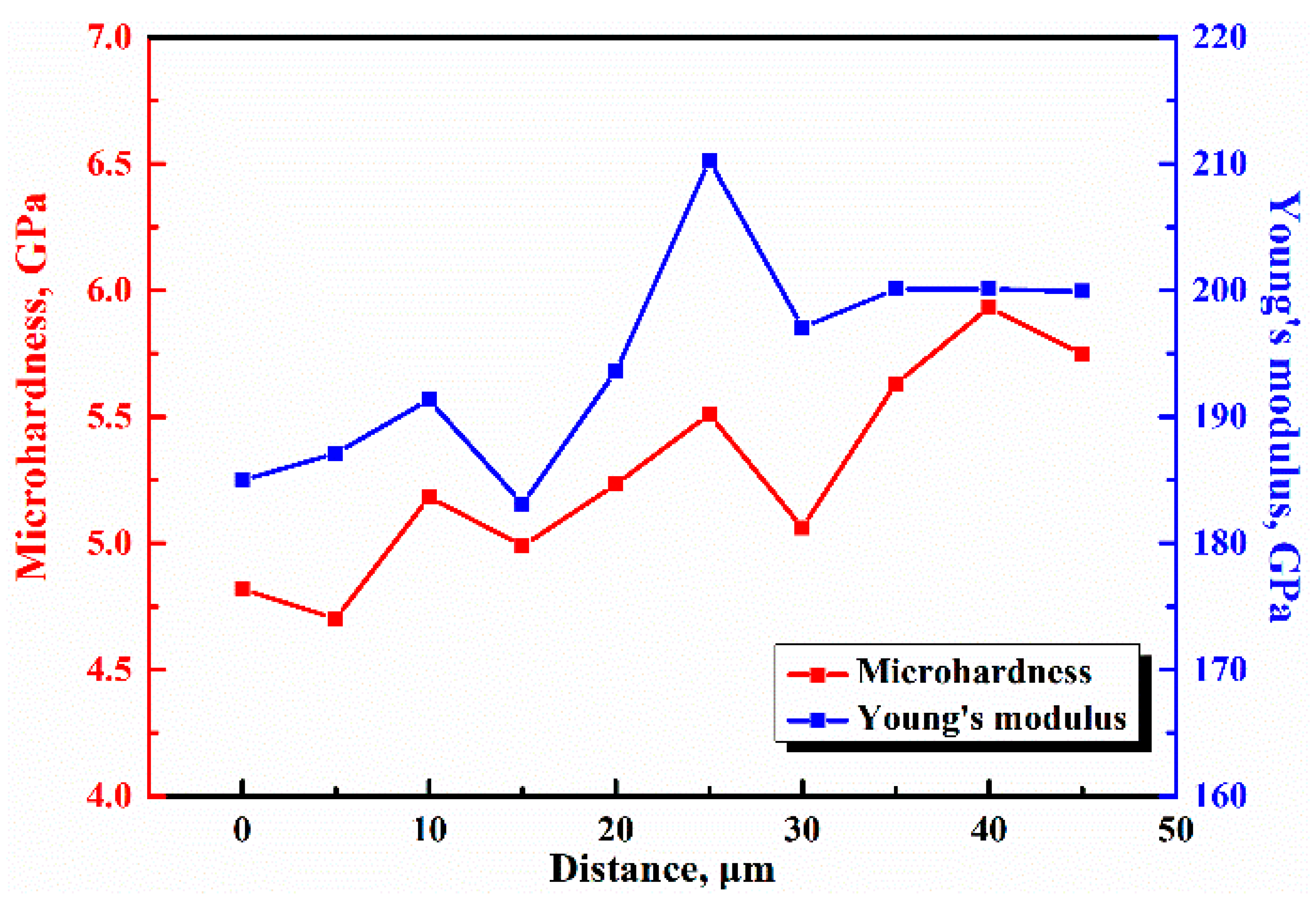
(3)
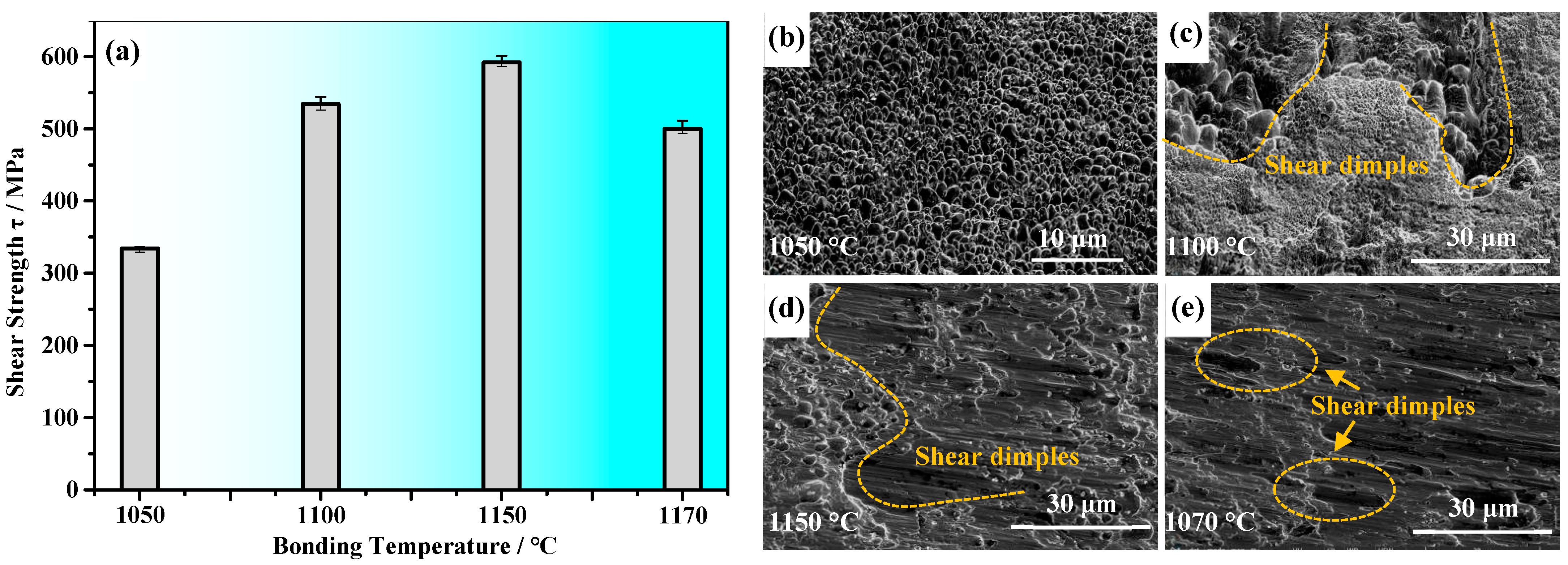
The microhardness and Young’s modulus of joint increased with an increase in the amount of γ′ phase. The microhardness and modulus of the DAZ near the MEA had the minimum 4.7 GPa and 183.2 GPa, while the DAZ adjacent to FGH98 reached the maximum 5.9 GPa and 210.3 GPa. The shear strength of the DB joint was increased initially and then decreased with the increase of bonding temperature from 1050 to 1170 °C. The peak value of joint shear strength was 592 MPa when the bonding temperature was 1150 °C, and the fracture morphology exhibited the typical shear dimples.

Author Contributions

Investigation, writing—original draft preparation, Y.D., Investigation, Z.L., Funding acquisition J.X., Investigation, Y.C., Data curation, S.L., Supervision, J.L., Funding acquisition, J.D. All authors have read and agreed to the published version of the manuscript.

Funding

This work was supported by the research fund of the National Natural Science Foundations of China (Grant Nos. 52075449, 51975480 and U1737205).

Institutional Review Board Statement

The study did not involve humans or animals.

Informed Consent Statement

The study did not involve humans or animals.

Data Availability Statement

The study did not report any data.

Acknowledgments

All individuals included in this paper have consented to the acknowledgement.

Conflicts of Interest

The authors declare they have no conflict of interest.

References

  1. Ma, Y.; Yuan, F.P.; Yang, M.X.; Jiang, P.; Ma, E.; Wu, X.L. Dynamic shear deformation of a CrCoNi medium-entropy alloy with heterogeneous grain structures. Acta Mater. 2018, 148, 407–418. [Google Scholar] [CrossRef] [Green Version]
  2. Miao, J.; Slone, C.E.; Smith, T.M.; Niu, C.; Bei, H.; Ghazisaeidi, M.; Pharr, G.M.; Mills, M.J. The evolution of the deformation substructure in a Ni-Co-Cr equiatomic solid solution alloy. Acta Mater. 2017, 132, 35–48. [Google Scholar] [CrossRef]
  3. Zhang, Z.J.; Sheng, H.W.; Wang, Z.J.; Gludovatz, B.; Zhang, Z.; George, E.P.; Yu, Q.; Mao, S.X.; Ritchie, R.O. Dislocation mechanisms and 3D twin architectures generate exceptional strength-ductility-toughness combination in CrCoNi medium-entropy alloy. Nat. Commun. 2017, 8, 14390. [Google Scholar] [CrossRef] [PubMed]
  4. Gludovatz, B.; Hohenwarter, A.; Thurston, K.V.; Bei, H.; Wu, Z.; George, E.P.; Ritchie, R.O. Exceptional damage-tolerance of a medium-entropy alloy CrCoNi at cryogenic temperatures. Nat. Commun. 2016, 7, 10602. [Google Scholar] [CrossRef]
  5. Wu, Z.; Bei, H.; Pharr, G.M.; George, E.P. Temperature dependence of the mechanical properties of equiatomic solid solution alloys with face-centered cubic crystal structures. Acta Mater. 2014, 81, 428–441. [Google Scholar] [CrossRef]
  6. Slone, C.E.; Miao, J.; George, E.P.; Mills, M.J. Achieving ultra-high strength and ductility in equiatomic CrCoNi with partially recrystallized microstructures. Acta Mater. 2019, 165, 496–507. [Google Scholar] [CrossRef]
  7. Liu, W.H.; Lu, Z.P.; He, J.Y.; Luan, J.H.; Wang, Z.J.; Liu, B.; Liu, Y.; Chen, M.W.; Liu, C.T. Ductile CoCrFeNiMox high entropy alloys strengthened by hard intermetallic phases. Acta Mater. 2016, 116, 332–342. [Google Scholar] [CrossRef]
  8. Zhao, Y.L.; Yang, T.; Tong, Y.; Wang, J.; Luan, J.H.; Jiao, Z.B.; Chen, D.; Yang, Y.; Hu, A.; Liu, C.T.; et al. Heterogeneous precipitation behavior and stacking-fault-mediated deformation in a CoCrNi-based medium-entropy alloy. Acta Mater. 2017, 138, 72–82. [Google Scholar] [CrossRef]
  9. Igor, M.; Jan, C.; Zuzana, K.; Jitka, N.; Michael, K.; Erich, N.; Ivo, K.; Vit, H.; Ivo, D. Mechanical and microstructural characterization of powder metallurgy CoCrNi medium entropy alloy. Mater. Sci. Eng. A 2017, 701, 370–380. [Google Scholar]
  10. Zhang, Y.; Jiang, X.S.; Fang, Y.; Fang, Y.J.; Liu, B.; Sun, H.L.; Shao, Z.Y.; Song, T.F. Research and development of welding methods and welding mechanism of high-entropy alloys: A review. Mater. Today Commun. 2021, 28, 102503. [Google Scholar] [CrossRef]
  11. Oliveira, J.P.; Curado, T.M.; Zeng, Z.; Lopes, J.G.; Rossinyol, E.; Park, J.M.; Schell, N.; Fernandes, F.B.; Kim, H.S. Gas tungsten arc welding of as-rolled CrMnFeCoNi high entropy alloy. Mater. Des. 2020, 189, 108505. [Google Scholar] [CrossRef]
  12. Chen, Z.; Wang, B.F.; Duan, B.H.; Zhang, X.Y. Mechanical properties and microstructure of laser welded FeCoNiCrMn high-entropy alloy. Mater. Lett. 2020, 262, 127060. [Google Scholar] [CrossRef]
  13. Yuan, L.; Xiong, J.T.; Ren, J.; Du, Y.J.; Li, J.L. Microstructure and mechanical properties in TLP joint of FeCoNiTiAl alloy and IC10 superalloy using Mn-Ni-Cr filler. Mater. Charact. 2021, 179, 111292. [Google Scholar] [CrossRef]
  14. Li, P.; Sun, H.T.; Wang, S.; Xia, Y.Q.; Dong, H.G.; Wen, G.D.; Zhang, H. Diffusion bonding of AlCoCrFeNi2.1 eutectic high entropy alloy to GH4169 superalloy. Mater. Sci. Eng. A 2020, 793, 139843. [Google Scholar] [CrossRef]
  15. Li, S.W.; Li, J.L.; Shi, J.M.; Du, Y.J.; Peng, Y.; Jin, F.; Xiong, J.T. Microstructure and mechanical properties of the brazed region in the AlCoCrFeNi high-entropy alloy and FGH98 superalloy joint. Mater. Sci. Eng. A 2021, 804, 140714. [Google Scholar] [CrossRef]
  16. Lei, Y.; Hu, S.P.; Yang, T.L.; Song, X.G.; Luo, Y.; Wang, G.D. Vacuum diffusion bonding of high-entropy Al0. 85CoCrFeNi alloy to TiAl intermetallic. J. Mater. Process. Technol. 2020, 278, 116455. [Google Scholar] [CrossRef]
  17. Peng, Y.; Li, J.L.; Shi, J.M.; Li, S.W.; Xiong, J.T. Microstructure and mechanical properties of diffusion bonded joints of high-entropy alloy Al5 (HfNbTiZr) 95 and TC4 titanium alloy. J. Mater. Res. Technol. 2021, 11, 1741–1752. [Google Scholar] [CrossRef]
  18. Li, P.; Sun, H.T.; Dong, H.G.; Xia, Y.Q.; Wang, S.; Hao, X.H. Microstructural evolution, bonding mechanism and mechanical properties of AlCoCrFeNi2.1 eutectic high entropy alloy joint fabricated via diffusion bonding. Mater. Sci. Eng. A 2021, 814, 141211. [Google Scholar] [CrossRef]
  19. Huang, H.L.; Liu, G.Q.; Wang, H.; Wang, Z.C.; Zhang, H.F.; Shao, Y.L.; Hu, B.F. Effect of cooling rate and resulting microstructure on tensile properties and deformation mechanisms of an advanced PM nickel-based superalloy. J. Alloys Compd. 2019, 805, 1254–1259. [Google Scholar] [CrossRef]
  20. Huang, G.C.; Liu, G.Q.; Feng, M.N.; Zhang, M.; Hu, B.F.; Wang, H. The effect of cooling rates from temperatures above the γ′ solvus on the microstructure of a new nickel-based powder metallurgy superalloy. J. Alloys Compd. 2018, 747, 1062–1072. [Google Scholar] [CrossRef]
  21. Zhang, X.; Li, H.W.; Zhan, M.; Zheng, Z.B.; Gao, J.; Shao, G.D. Electron force-induced dislocations annihilation and regeneration of a superalloy through electrical in-situ transmission electron microscopy observations. J. Mater. Sci. Technol. 2020, 36, 79–83. [Google Scholar] [CrossRef]
  22. Zhang, L.X.; Chang, Q.; Sun, Z.; Yang, Z.Y.; Feng, J.C. Diffusion bonding of hydrogenated TC4 alloy and GH3128 superalloy using composite interlayers. J. Mater. Process. Technol. 2019, 274, 116266. [Google Scholar] [CrossRef]
  23. Zhang, Y.; Jiang, X.S.; Fang, Y.J.; Sun, H.L.; Song, T.F.; Mo, D.F.; Li, X.; Luo, Z.P. Vacuum diffusion bonding of CoCrFeNiMo MEAs and Inconel 718 using Ni interlayer. Mater. Lett. 2020, 279, 128509. [Google Scholar] [CrossRef]
  24. Yang, Z.W.; Lian, J.; Wang, J.; Cai, X.Q.; Wang, Y.; Wang, D.P.; Wang, Z.M.; Liu, Y.C. Diffusion bonding of Ni3Al-based alloy using a Ni interlayer. J. Alloy. Compd. 2020, 819, 153324. [Google Scholar] [CrossRef]
  25. Peng, Y.; Li, J.L.; Peng, X.; Li, S.W.; Xiong, J.T.; Shi, J.M. Interfacial microstructure evolution and formation process of the joints prepared by diffusion bonding on DD6 nickel-based single crystal superalloy. J. Mater. Res. Technol. 2020, 9, 16317–16328. [Google Scholar] [CrossRef]
Figure 1. The microstructure of base materials and the work piece and shear test apparatus showing (a) FGH98, (b) Al3Ti3(CrCoNi)94, (c) work piece, and (d) shear test apparatus.
Crystals 11 01158 g001
Figure 2. The morphology of joints bonded at different temperature, showing (a1) 1050 °C, (b1) 1100 °C, (c1) 1150 °C and (d1) 1170 °C. (a2d2) magnified figures of zones marked by white rectangles.
Crystals 11 01158 g002
Figure 3. The EPMA results of joints bonded by 1150 °C with the corresponding elements distribution map showing (a) test location, (b) Co, (c) Cr, (d) Ti, (e) Al, (f) Ni, (g) Ta, (h) Mo and (i) W.
Crystals 11 01158 g003
Figure 4. TEM-EDS result of phase with different morphologies: (a1) HADDF image of interface and corresponding elemental distribution maps of (a2a6), (b) the enlarged view of Zone II, (c) the enlarged view of Zone III.
Crystals 11 01158 g004
Figure 5. TEM result of phase with different morphologies: (a1,b1) the dark image of phase, (a2,b2) the SAED image of phase, (a3,b3) the HRTEM image of phase interface.
Crystals 11 01158 g005
Figure 6. The nanoindentation result of joint bonded by 1150 °C-5MPa-1h.
Crystals 11 01158 g006
Figure 7. The shear strength and corresponding fracture morphologies of bonding joints with different temperature showing (a) shear strength and (be) fracture morphologies of joints at 1050–1170 °C.
Crystals 11 01158 g007
Table 1. The composition of FGH98 and Al3Ti3(CrCoNi)94 (at, %).
MaterialsAlCoCrTiTaNbMoWZrBCNi
FGH987.4419.9414.164.50.770.561.581.200.030.560.7148.55
MEA3.1231.2130.922.88 31.87
Table 2. The diffusion bonding parameters of FHG98 and MEA.
NumberWelding Temperature
T/°C
Welding: Pressure
P/MPa
Welding Time
t/h
Heat Treatment
Temperature, T/°C
Heat Treatment
Time, t/h
No.11050518503
No.21100
No.31150
No.41170
Table 3. Composition of phases in bonding joints (at, %).
PointAlTiNiCrCoPossible Phase
18.810.970.02.67.6Ni3(Al, Ti)
28.09.566.65.59.9
Publisher’s Note: MDPI stays neutral with regard to jurisdictional claims in published maps and institutional affiliations.

