Article

Growth and Scintillation Properties of Directionally Solidified Ce:LaBr3/AEBr2 (AE = Mg, Ca, Sr, Ba) Eutectic System

1
New Industry Creation Hatchery Center (NICHe), Tohoku University, 6-6-10 Aoba, Aramaki, Aoba-ku, Sendai 980-8579, Japan
2
C&A Corporation, 1-16-23 Ichibancho, Aoba-ku, Sendai 980-0811, Japan
3
Institute for Material Research (IMR), Tohoku University, 2-1-1 Katahira, Aoba-ku, Sendai 980-8577, Japan
*
Author to whom correspondence should be addressed.
Crystals 2020, 10(7), 584; https://doi.org/10.3390/cryst10070584
Submission received: 5 June 2020 / Revised: 29 June 2020 / Accepted: 2 July 2020 / Published: 6 July 2020
(This article belongs to the Section Inorganic Crystalline Materials)

Abstract

:
Ce-doped LaBr3/AEBr2 (AE = Mg, Ca, Sr, Ba) eutectics were grown using the Bridgman–Stockbarger (BS) method in quartz ampoules. The eutectics (AE = Mg and Ca) showed optical transparency like optical fiber bundles. A grown Ce-doped LaBr3/MgBr2 eutectic shows a 355 nm emission ascribed to Ce3+ 4f-5d transition under X-ray excitation. The smaller the ionic size of AE, the higher the light yield of the sample was. The light yield of Ce:LaBr3/MgBr2 was 34,300 photon/MeV, which is higher than Ce:LYSO standard. Scintillation decay time under 662 keV gamma-ray excitation was 18.8 ns.

1. Introduction

Scintillators coupled with photodetectors are widely used in radiation imaging applications such as medical imaging, security, high-energy physics, astrophysics, oil well logging, etc. In order to meet the needs of these applications, a deeper knowledge of crystal physics and all the mechanisms involved in their scintillating behavior is important [1]. In conventional high-resolution radiation imaging systems employing inorganic scintillators, scintillation light must be guided to photo-sensors efficiently without lateral light diffusion [2]. In X-ray imaging applications, radiation imaging sensors are composed of photodetector arrays and an indirect flat panel detector (FPD) coupled with a scintillator plate such as Tl:CsI [3,4] or Tb:Gd2O2S (GOS) [5,6]. Improvement in spatial resolution is required in this application. However, columnar grown Tl:CsI reduces the spatial resolution because of light scattering in micrometer size Tl:CsI fiber crystals [3]. Light diffusion through scintillator materials on photodetector degrades the resolution of radiation imaging sensors and limits sensitivity. Recently, pixelated photodetector arrays have been improved in order to achieve a micrometer scale spatial resolution. However, the pixel size of scintillator arrays and light diffusion limit the spatial resolution. Moreover, X-ray energy-resolved counting systems using silicon photomultipliers (SiPM) and scintillators are being developed now. In such systems, inorganic scintillators with fast and good energy resolution are required [7].
Currently, submicron-diameter phase-separated scintillator fibers (PSSFs) have been reported and they have both characteristics of optical fiber and a radiation-to-light conversion. PSSFs were realized by a directionally solidified eutectic (DSE) growth in previous research [8,9,10,11,12]. In PSSFs, the emitted scintillation is confined and transported along the eutectic structure by a total reflection mode, so that light diffusion can be reduced and high-resolution imaging can be achieved. Research on PSSFs such GAP/α-Al2O3 [13,14], SrHfO3/Al2O3 [15], Gd2Si2O7/SiO2 [16], and LiF/CaF2/LiBaF3 [17] has been previously reported by our group.
In order to find a good combination of eutectic structure with PSSFs, the choice of scintillator materials is important. The Ce:LaBr3 scintillator has attracted attention due to its high light yield of over 74,000 photon/MeV and fast decay time of around 20 ns, with enough density of 5.1 g/cm3 for low energy X-ray detection even though it is hygroscopic [18,19]. In this research, exploration of PSSFs by directional crystal growth method is reported. Ce-doped LaBr3/AEBr2 (AE = Mg, Ca, Sr, Ba) eutectics were investigated. Here, we designed the matrix AEBr2 phase and scintillation LaBr3 fibers at the eutectic point of LaBr3/AEBr2 (See Figure 1). Crystal growth was performed using the Bridgman–Stockbarger (BS) method at the eutectic point. Investigations of the crystal structure and eutectic phase were performed. Luminescence and scintillation properties were also evaluated.

2. Experimental Procedure
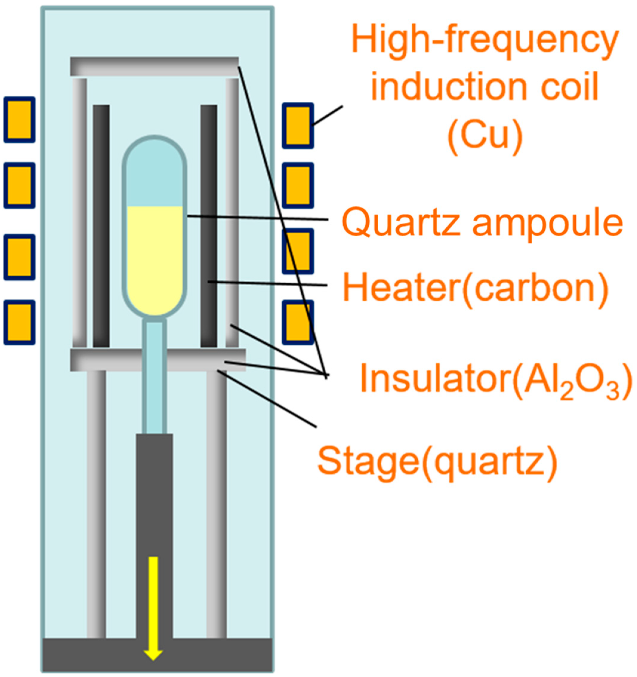
2.1. Crystal Growth

The starting materials were prepared from high-purity halide powders of CeBr3, LaBr3, and AEBr2 (3N, produced by APL, AE = Mg, Ca, Sr, Ba) according to the molar ratio of AEBr2:LaBr3:CeBr3 = 75:24.75:0.25. Crystal growth was carried out via the BS method in a quartz ampoule with an inner diameter of 4 mm for AE = Ca and an inner diameter of 8 mm for AE = Mg, Sr, and Ba. Details of crystal growth by the BS method are given in Figure 2. In the unidirectional solidification processes, LaBr3 and AEBr2 phases deposit from the melt on their own formed solid phases. The mixed powders were put into a quartz ampoule inside the glovebox in 9N Ar atmosphere. The quartz ampoule was then taken from the glovebox and baked in high vacuum (~10−4 Pa) at 200 °C using 9N purity Ar and SiCl4 gas to remove water and oxygen. We carefully evacuated and sealed off the ampoule with an oxyhydrogen burner. After sealed cutting, each ampoule was set into a furnace and heated by a carbon heater with the radio-frequency induction coil. The pull down speed for crystal growth was 0.5 mm/min. After the crystal growth was finished, the furnace was gradually cooled down to room temperature. Plates with a thickness of 1 mm were cut from the grown samples. They were double side polished for back-scattered electron image (BEI) evaluation, luminescence, and scintillation property measurements.

2.2. Structural Evaluation of Eutectic Composites

From the grown crystals, round and rectangular samples with a thickness of 1 mm were obtained and the cut surface was optically polished. The eutectic phase structure in the grown crystals was observed by BEI (S-3400N SEM, Hitachi, Tokyo, Japan). The eutectic structures in transverse and vertical cross-sections were observed. The obtained phases in the eutectics were investigated by powder X-ray diffraction (XRD) in the 2θ range from 20 to 60° using X-ray diffractometer (RINT-2000, Rigaku, Akishima, Japan). The X-ray source was CuKα with an accelerating voltage of 40 kV and tube current of 40 mA.

2.3. Measurements of Luminescence and Scintillation Properties

The radioluminescence spectra under X-ray irradiation (40 mV, 30 mA) were recorded with a spectrometer (SR-163, Andor Technology, Belfast, UK), equipped with a spectroscopy CCD detector (DU920P, Andor Technology, Belfast, UK). The light output was measured using a photomultiplier tube (PMT) (R7600U-200, Hamamatsu Photonics, Hamamatsu, Japan) with an ultra bialkali photocathode. The samples were coupled with the PMT using silicone grease (OKEN, 6262A) and covered using Teflon-tape. To determine the light yield, the energy spectra were collected under 662 keV γ-ray excitation (137Cs source) using a PMT. The signal was fed into a shaping amplifier (572A, ORTEC, Oak Ridge, TN, USA), digitized by a multichannel analyzer (MCA) (926, ORTEC, Oak Ridge, TN, USA), and finally sent to a personal computer. The shaping time was set to 2 μs. The bias for the PMT was supplied by ahigh-voltage power supply (ORTEC, Oak Ridge, TN, USA). The same setting as the PMT and digital oscilloscope (TDS 5032B, Tektronix, Beaverton, OR, USA) was used to measure the scintillation decay time.

3. Results and Discussion

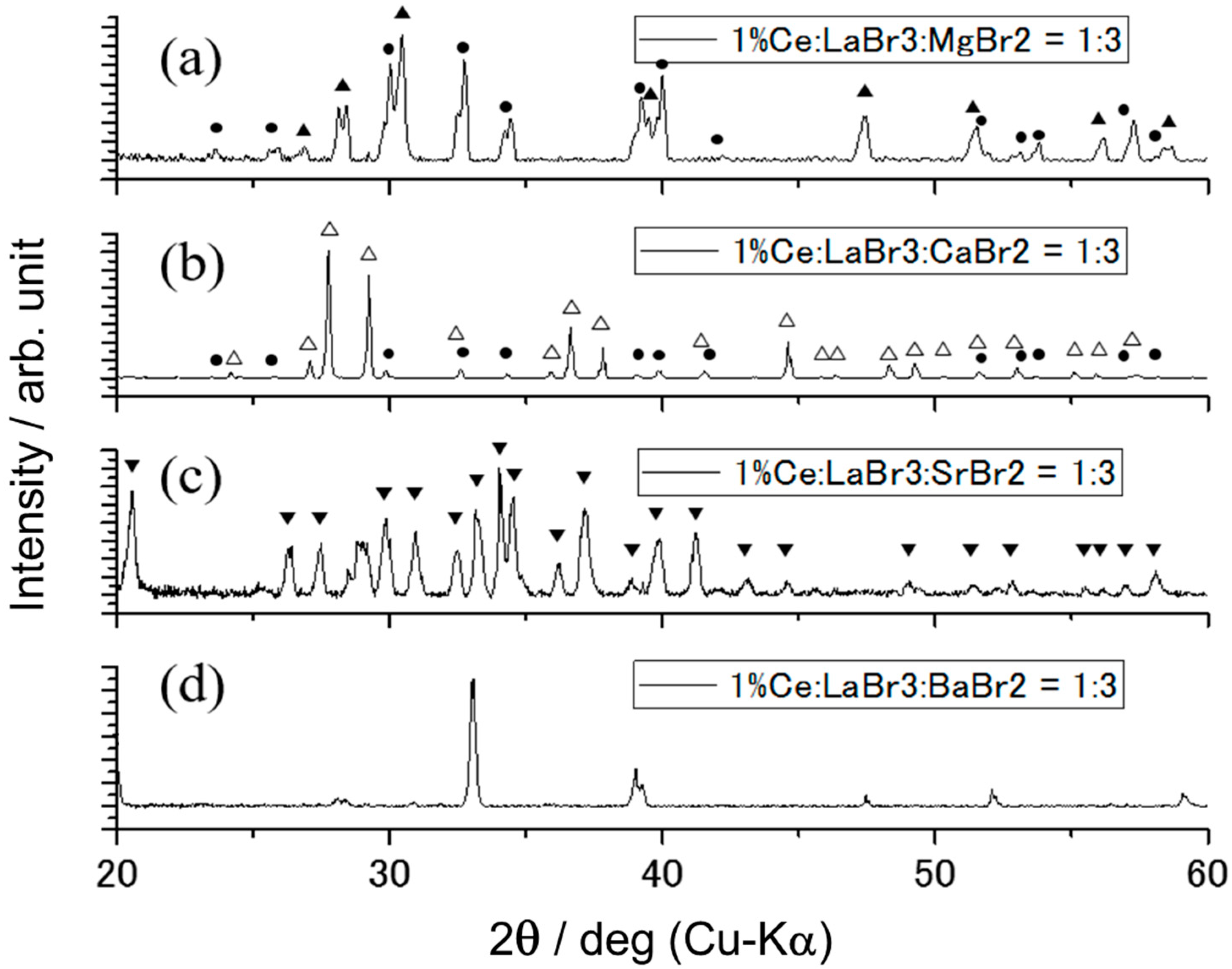
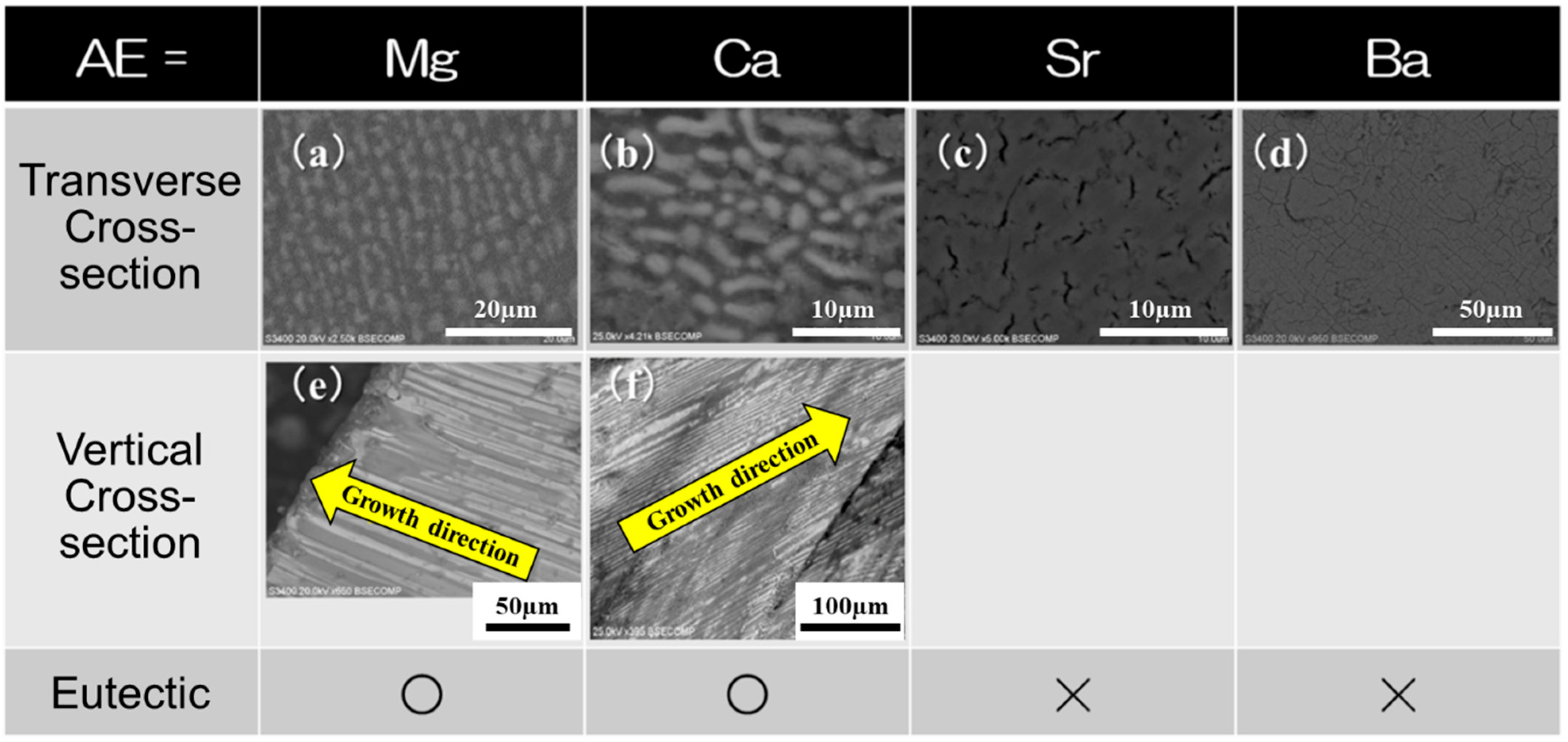
3.1. DSE System of LaBr3/AEBr2 Eutectic

White rod-shaped samples were obtained via the BS method. Grown samples and 1 mm thick plates after polishing are shown in Figure 3. For AE = Mg or Ca, the samples showed optical transparency like optical fiber bundles. Therefore, the background line was visible on the surface through the transparent rods grown in the material, while the samples were not transparent through the radial direction. For AE = Sr or Ba, the samples showed optical transparency. Therefore, the background line was visible on the surface through the grown crystal, and the samples were semitransparent through the radial direction.
The grown samples were crushed into powder in a glovebox in 9N Ar atmosphere and packaged into an atmosphere-controllable sample case. Powder XRD measurements were performed using the sample case. The results of powder XRD of the grown samples were shown in Figure 4. For AE = Mg or Ca, the grown eutectics showed two main phases of LaBr3 (crystal system: hexagonal, space group: P63/m) and MgBr2 (crystal system: trigonal, space group: P-3m1), or CaBr2 (crystal system: trigonal, space group: Pnnm). For AE = Sr or Ba, the grown samples showed only a single phase. For AE = Sr, the main phase was SrBr2 (Crystal System: tetragonal, Space Group: P4/n z). Almost all peaks were SrBr2 peaks except for a peak around 29 degrees, which was assumed to be a trace of hydroxyl bromide coming from a hygroscopic characteristic of LaBr3 and SrBr2 or BaBr2 during the crushing. For AE = Ba, main phase had an unknown composition. That main phase was thought to be a compound of LaBr3 and BaBr2. The powder XRD pattern of this compound has not been identified with the existing powder diffraction file (PDF) database. Therefore, additional research is needed for detailed phase identification. The BEI of the grown samples in vertical and transverse cross-sections are shown in Figure 5. For AE = Mg or Ca, the grown eutectic structure showed a mixture of the rod and plate shapes of LaBr3 phase surrounded by a MgBr2 or CaBr2 matrix. This mixed structure of LaBr3 was aligned with a length of around 150–200 μm. Previously, some groups have investigated transformation between the rod-like shape and lamellar shape in eutectic structure [20,21,22,23]. They concluded that the transformation of the eutectic depended on the volume ratio of components and the relative interface energy. The rod-like shape can be obtained at a volume ratio of around 30–40% [24]. Volume ratio of LaBr3:AEBr2 in this system is about 25:75, and the LaBr3/CaBr2 or LaBr3/MgBr2 eutectic can take a rod-like shape structure by optimizing temperature gradient along the growth direction and growth rate [25]. Scintillation light from LaBr3 phase shows around 57° of total reflection at the interface. In this report, though a well-aligned rod-like shape structure could not be obtained, optical transparency like optical fiber bundles was observed in the eutectic. For AE = Sr or Ba, the grown crystal did not show a LaBr3/AEBr2 eutectic structure and showed only one phase.

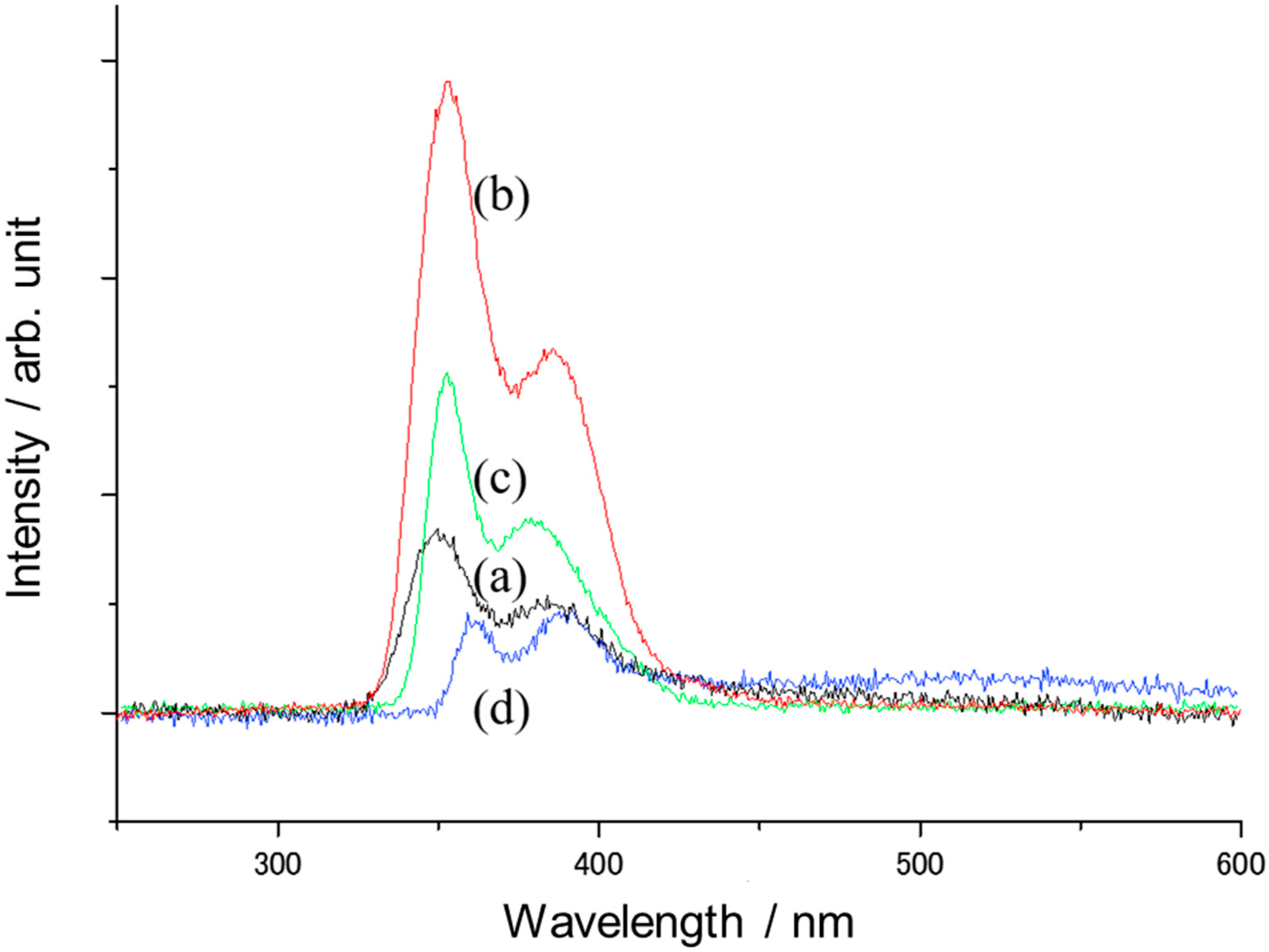
3.2. Luminescence and Scintillation Properties

Radioluminescence spectra of the grown Ce-doped LaBr3/AEBr2 (AE = Mg, Ca, Sr, Ba) eutectic measured under X-ray irradiation are shown in Figure 6. All samples show the typical double-band Ce3+ 5d-4f emission with maxima at around 355 and 385 nm according to the transitions into the 2F5/2 and 2F7/2 states, respectively. These results are in good agreement with previous reports [18,19]. Emission peaks were slightly shifted to the short wavelength region except for AE = Ba (AE = Mg:350 nm, 383 nm, AE = Ca:354 nm, 384 nm, AE = Sr:353 nm, 379 nm). For AE = Ba, emission peaks were slightly shifted to the long wavelength region (362 nm, 389 nm), due to its difference in crystal structure.
The pulse-height spectra of the eutectic sample excited by 662 keV gamma-rays of 137Cs at room temperature and measured using the PMT are shown in Figure 7. Light outputs of the samples were around 1.07, 0.53, 0.43, and 0.18 of the Ce:LYSO standard with 32,000 photon/MeV [26,27] for AE = Mg, Ca, Sr, Ba, respectively. Therefore, light outputs of samples were around 34,300, ~17,000, ~14,000, and ~6000 photon/MeV for AE = Mg, Ca, Sr, and Ba, respectively. The scintillation decay curves of the samples excited by 662 keV gamma-rays are shown in Figure 8. In the case of LaBr3/BaBr2, enough intensity of the decay curve signal was not detected due to its weak light output. Table 1 shows the survey of light yield and scintillation decay time values for all samples. For all samples, decay times were comparable to Ce:LaBr3 single crystal and had slower components except for LaBr3/MgBr2. This matches with past results [18,19]. The smaller the ionic size of AE, the faster the components decay.

4. Conclusions

Ce-doped LaBr3/AEBr2 (AE = Mg, Ca, Sr, Ba) eutectics were grown via the BS method in a quartz ampoule. For AE = Mg, Ca grown samples showed a LaBr3/AEBr2 eutectic structure. They showed optical transparency only for the growth direction through transparent rods grown in the material, while they were not transparent through the radial direction. They showed a mixture of rod and plate shapes. This mixed structure was aligned with a length of around 150–200 μm. For AE = Sr, Ba grown samples did not show a LaBr3/AEBr2 eutectic structure and showed a single phase. The Ce:LaBr3/AEBr2 samples showed a 355 nm emission ascribed to Ce3+ 4f-5d transition under X-ray excitation. Light outputs of samples were around 34,300, ~17,000, ~14,000, and ~6,000 photon/MeV for AE = Mg, Ca, Sr, and Ba, respectively. Scintillation decay times under 662 keV gamma-rays were 18.8 ns (100%) for LaBr3/MgBr2, 22.4 ns (60%) and 185 ns (40%) for LaBr3/CaBr2, 38.6 ns (44%), and 299.8 ns (56%) for LaBr3/SrBr2. The smaller the ionic size of AE, the faster the components’ decay. We demonstrated the possibility of a hygroscopic halide eutectic scintillator with a fast scintillation response. The light output of the Ce:LaBr3/MgBr2 eutectic was higher than Ce:LYSO standard and can be increased by getting well-aligned rod-shaped eutectic structures and improving optical transparency. If large size crystal growth and material processes for imaging application are established, LaBr3-based fast eutectic scintillators can be used for radiation imaging applications such as pulse counting X-ray imaging, which requires both fast timing and high-resolution performance.

Author Contributions

Conceptualization, K.K.; Data curation, K.K. and K.J.K.; Formal analysis, K.K. and M.Y.; Funding acquisition, K.K. and K.J.K.; Investigation, Y.F., H.C. and R.M.; Methodology, K.J.K. and S.K.; Project administration, A.Y. (Akira Yoshikawa); Supervision, A.Y. (Akira Yoshikawa); Validation, A.Y. (Akihiro Yamaji), Y.S., S.T., H.S., Y.Y. and Y.O.; Writing—original draft, K.K. and K.J.K.; Writing—review & editing, K.J.K. and V.V.K. All authors have read and agreed to the published version of the manuscript.

Funding

This work was partially supported by (i) Japan Society for the Promotion of Science (JSPS) Grants-in-Aid for Scientific Research (KAKENHI) Project ID 19164606, 19164252, 19132801, 17920611 and 18057417, (ii) Projects to support the advancement of strategic core technologies, Czech Science foundation No. 15-18300Y, and MEYS No. SOLID21 CZ.02.1.01/0.0/0.0/16_019/0000760 projects, (iii) Crystal Clear Collaboration in CERN.

Conflicts of Interest

The authors declare no conflict of interest.

References

  1. Rinaldi, D.; Montalto, L. Scintillator crystals: Structure, characterization and models for better performances. Crystals 2020, 10, 96. [Google Scholar] [CrossRef] [Green Version]
  2. Tyrrell, G.C. Phosphors and scintillators in radiation imaging detectors. Nucl. Instrum. Methods Phys. Res. Sect. A 2005, 546, 180–187. [Google Scholar] [CrossRef]
  3. Nagarkar, V.V.; Gaysinskiy, V.; Shestakova, I.; Singh, B.; Teo, K.; Sun, M.; Barber, W.C.; Hasegawa, B. Near simultaneous combined SPECT/CT imaging using an EMCCD. IEEE Nucl. Sci. Symp. Conf. Rec. 2005, 4, 2607–2610. [Google Scholar]
  4. Michail, C.; Valais, I.; Seferis, I.; Kalyvas, N.; Fountos, G.; Kandarakis, I. Experimental measurement of a high resolution CMOS detector coupled to CsI scintillators under X-ray radiation. Radiat. Meas. 2015, 74, 39–46. [Google Scholar] [CrossRef]
  5. Blasse, G.; Grabmaier, B.C. Luminescent Materials; Springer: Berlin/Heidelberg, Germany, 1994. [Google Scholar]
  6. Howansky, A.; Lubinsky, A.R.; Suzuki, K.; Ghose, S.; Zhao, W. An apparatus and method for directly measuring the depth-dependent gain and spatial resolution of turbid scintillators. Med. Phys. 2018, 45, 4927–4941. [Google Scholar] [CrossRef]
  7. Philippov, D.; Popova, E.; Vinogradov, S.; Stifutkin, A.; Pleshko, A.; Klemin, S.; Ilyin, A.; Belyaev, V.; Besson, D.; Vandychev, M. Development of SiPM-based X-ray counting scanner for human inspection. IEEE Trans. Nucl. Sci. 2018, 65, 2013–2020. [Google Scholar] [CrossRef]
  8. Llorca, J.; Orera, V.M. Directionally solidified eutectic ceramic oxides. Prog. Mater. Sci. 2006, 51, 711–809. [Google Scholar] [CrossRef]
  9. Pawlak, D.A.; Kolodziejak, K.; Turczynski, S.; Kisielewski, J.; Rozniatowski, K.; Diduszko, R.; Kaczkan, M.; Malinowski, M. Self-organized, rodlike, micrometer-scale microstructure of Tb3Sc2Al3O12-TbScO3:Pr eutectic. Chem. Mater. 2006, 18, 2450–2457. [Google Scholar] [CrossRef]
  10. Bei, H.; George, E.P. Microstructures and mechanical properties of a directionally solidified NiAl-Mo eutectic alloy. Acta Mater. 2005, 53, 69–77. [Google Scholar] [CrossRef]
  11. Yanagida, T.; Fukuda, K.; Fujimoto, Y.; Kawaguchi, N.; Kurosawa, S.; Yamazaki, A.; Watanabe, K.; Futami, Y.; Yokota, Y.; Pejchal, J.; et al. Eu-doped 6LiF-SrF2 eutectic scintillators for neutron detection. Opt. Mater. 2012, 34, 868–871. [Google Scholar] [CrossRef]
  12. Ohashi, Y.; Yasui, N.; Yokota, Y.; Yoshikawa, A.; Den, T. Submicron-diameter phase-separated scintillator fibers for high-resolution X-ray imaging. App. Phy. Lett. 2013, 102, 05197. [Google Scholar] [CrossRef]
  13. Ohashi, Y.; Yasui, N.; Suzuki, T.; Watanabe, M.; Den, T.; Kamada, K.; Yokota, Y.; Yoshikawa, A. Orientation relationships of unidirectionally aligned GdAlO3/Al2O3 eutectic fibers. J. Eur. Ceram. Soc. 2014, 34, 3849–3857. [Google Scholar] [CrossRef]
  14. Kamada, K.; Yasui, N.; Ohashi, Y.; Den, T.; Yamaguchi, H.; Yamaji, A.; Shoji, Y.; Yoshisno, M.; Kim, K.J.; Kurosawa, S.; et al. Optimization of dopants and scintillation fibers’ diameter of GdAlO3/α-Al2O3 eutectic for high-resolution X-ray imaging. IEEE Trans. Nucl. Sci. 2018, 65, 2036–2040. [Google Scholar] [CrossRef]
  15. Kamada, K.; Kurosawa, S.; Shoji, Y.; Pejchal, J.; Ohashi, Y.; Yokota, Y.; Yoshikawa, A. Luminescence and scintillation properties of Ce dope SrHfO3 based eutectics. Opt. Mater. 2015, 41, 41–44. [Google Scholar] [CrossRef] [Green Version]
  16. Kamada, K.; Kurosawa, S.; Murakami, R.; Yokota, Y.; Pejchal, J.; Ohashi, Y.; Yoshikawa, A. Growth and scintillation properties of Ce doped Gd2Si2O7/SiO2 eutectics. J. Phys. Conf. Ser. 2015, 619, 012036. [Google Scholar] [CrossRef] [Green Version]
  17. Hishinuma, K.; Kamada, K.; Kurosawa, S.; Yamaji, A.; Pejchal, J.; Yokota, Y.; Ohashi, Y.; Yoshikawa, A. LiF/CaF2/LiBaF3 ternary fluoride eutectic scintillator. Jpn. J. Appl. Phys. 2015, 54, 04DH04. [Google Scholar] [CrossRef] [Green Version]
  18. Alekhin, M.S.; de Haas, J.T.M.; Khodyuk, I.V.; Krämer, K.W.; Menge, P.R.; Ouspenski, V.; Dorenbos, P. Improvement of γ-ray energy resolution of LaBr3:Ce3+ scintillation detectors by Sr2+ and Ca2+ co-doping. App. Phy. Lett. 2013, 102, 161915. [Google Scholar] [CrossRef] [Green Version]
  19. Van Loef, E.V.D.; Dorenbos, P.; van Eijk, C.W.E.; Krämer, K.W.; Gudel, H.U. Scintillation properties of LaBr3:Ce3+ crystals: Fast, efficient and high-energy-resolution scintillators. Nucl. Instrum. Methods Phys. Res. A 2002, 486, 254–258. [Google Scholar] [CrossRef]
  20. Yoshikawa, A.; Epelbaum, B.M.; Hasegawa, K.; Durbin, S.D.; Fukuda, T. Microstructures in oxide eutectic fibers grown by a modified micro-pulling-down method. J. Cryst. Growth 1999, 205, 305–316. [Google Scholar] [CrossRef]
  21. Jackson, K.A.; Hunt, J.D. Lamellar and rod eutectic growth. Trans. Metall. Soc. AIME 1966, 236, 1129. [Google Scholar]
  22. Hunt, J.D.; Chilton, J.P. An investigation of the lamellar and rod transition in binary eutectics. J. Inst. Met. 1962, 11, 338. [Google Scholar]
  23. Orera, V.M.; Pena, J.I.; Oliete, P.B.; Merino, R.I.; Larrea, A. Growth of eutectic ceramic structures by directional solidification methods. J. Cryst. Growth 2012, 360, 99–104. [Google Scholar] [CrossRef] [Green Version]
  24. Oliete, P.B.; Mesa, M.C.; Merino, R.I.; Orera, V.M. Processing, microstructure and optical properties of the directionally solidified Al2O3–EuAlO3 eutectic rods. J. Cryst. Growth 2012, 360, 123–126. [Google Scholar] [CrossRef] [Green Version]
  25. Liu, S.; Lee, J.H.; Trivedi, R. Dynamic effects in the lamellar–rod eutectic transition. Acta Mater. 2011, 59, 3102–3115. [Google Scholar] [CrossRef]
  26. Melcher, C.L.; Schweitzer, J.S. Cerium-doped lutetium oxyorthosilicate: A fast, efficient new scintillator. IEEE Trans. Nucl. Sci. 1992, 39, 502–505. [Google Scholar] [CrossRef]
  27. Pidol, L.; Kahn-Harari, A.; Viana, B.; Virey, E.; Ferrand, B.; Dorenbos, P.; de Haas, J.T.M.; van Eijk, C.W.E. High efficiency of lutetium silicate scintillators, Ce-doped LPS, and LYSO crystals. IEEE Trans. Nucl. Sci. 2004, 51, 1084–1087. [Google Scholar] [CrossRef]
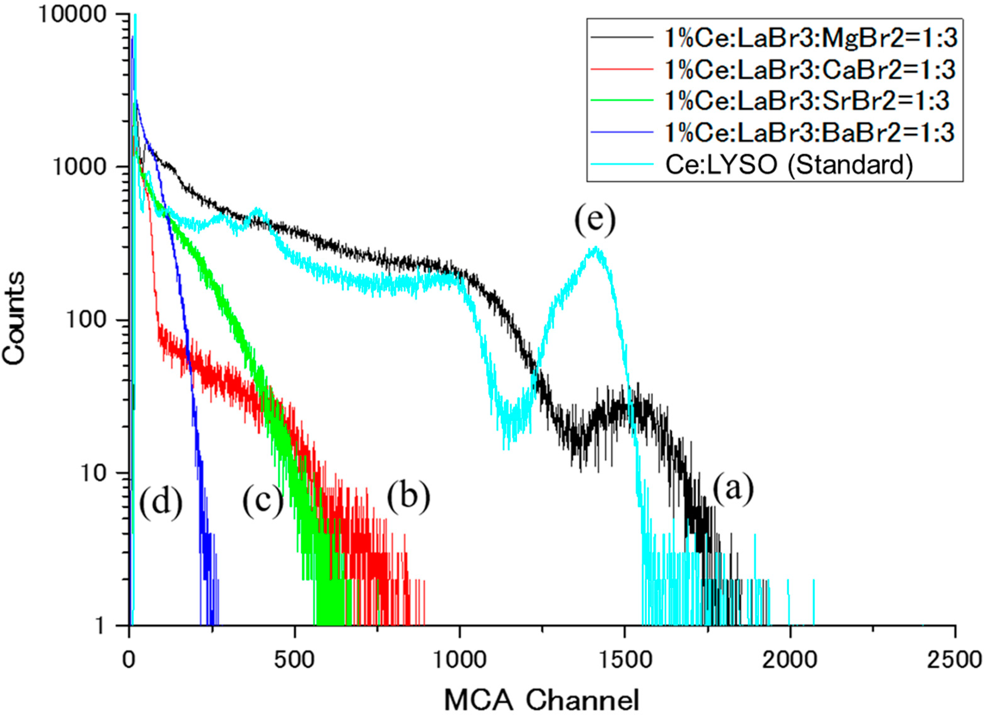
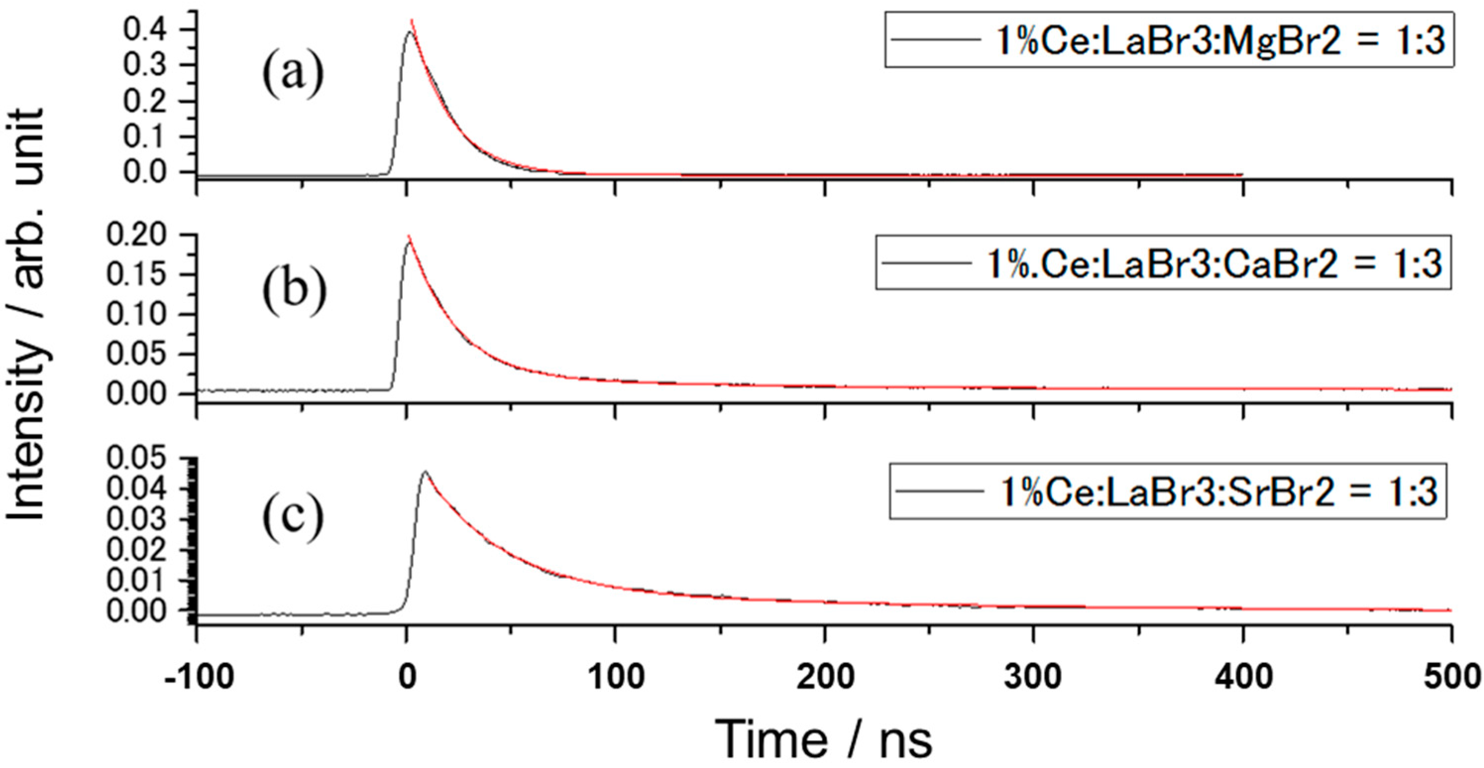
Figure 1. Schematic diagram of generation of scintillation light in the eutectic.
Crystals 10 00584 g001
Figure 2. The schematic drawing of crystal growth via the Bridgman–Stockbarger (BS) method. The ampoules used have outer and inner diameters of 10 and 8 mm, respectively.
Crystals 10 00584 g002
Figure 3. Photographs of the (ad) as grown Ce:LaBr3/AEBr2 samples (AE = Mg, Ca, Sr, Ba) and (eh) cross-section polished samples (AE = Mg, Ca, Sr, Ba).
Crystals 10 00584 g003
Figure 4. X-ray diffraction patterns of grown samples. (a) AE = Mg, (b) AE = Ca, (c) AE = Sr, (d) AE = Ba. (●): peaks of LaBr3 (hexagonal, P63/m), (▲): peaks of MgBr2 (trigonal, P-3mL), (△): peaks of CaBr2 (trigonal, Pnnm), (▼): peaks of SrBr2 (tetragonal, P4/n z).
Crystals 10 00584 g004
Figure 5. Back-scattered electron image (BEI) of the polished LaBr3/AEBr2 crystals, (ad) transverse cross-section for AE = Mg, Ca, Sr, Ba and (e,f) vertical cross-section along growth direction for AE = Mg and Ca.
Crystals 10 00584 g005
Figure 6. Radioluminescence spectra of the grown samples measured under X-ray irradiation. (a) AE = Mg, (b) AE = Ca, (c) AE = Sr, (d) AE = Ba.
Crystals 10 00584 g006
Figure 7. Energy spectra of the grown samples and Ce:LYSO standard. Excitation by 137Cs radioisotope (662 keV). (a) AE = Mg, (b) AE = Ca, (c) AE = Sr, (d) AE = Ba, (e) Ce:LYSO standard.
Crystals 10 00584 g007
Figure 8. Scintillation decay curves of the grown samples. Excitation by 137Cs radioisotope (662 keV). (a) AE = Mg, (b) AE = Ca, (c) AE = Sr.
Crystals 10 00584 g008
Table 1. Light output and decay components of the Ce:LaBr3/AEBr2 samples (AE = Mg, Ca, Sr, Ba).
Peak ChannelLight Yield
(Photon/MeV)
Scintillation Decay Time
1st Component (ns)2nd Component (ns)
LaBr3/MgBr2151234,30018.8 (100%)-
LaBr3/CaBr2750~17,00022.4 (60%)185 (40%)
LaBr3/SrBr2620~14,00038.6 (44%)299.8 (56%)
LaBr3/BaBr2250~6000N.D.N.D.
N.D.: Not detected.

