Article

Enhanced Mechanical Properties of Surface Treated AZ31 Reinforced Polymer Composites

1
School of Chemical and Materials Engineering, National University of Sciences and Technology (NUST), Sector H-12, Islamabad 44000, Pakistan
2
Department of Metallurgical & Materials Engineering (MME), University of Engineering and Technology (UET), Lahore 54890, Pakistan
3
Department of Metallurgy and Materials Engineering, University of Engineering and Technology, Taxila 47050, Pakistan
4
Department of Mechanical and Industrial Engineering, College of Engineering, Majmaah University, Riyadh 11952, Saudi Arabia
5
Engineering and Applied Science Research Center, Majmaah University, Riyadh 11952, Saudi Arabia
6
Department of Mechanical Engineering, College of Engineering, Prince Sattam bin Abdulaziz University, AlKharj 11942, Saudi Arabi
*
Authors to whom correspondence should be addressed.
Crystals 2020, 10(5), 381; https://doi.org/10.3390/cryst10050381
Submission received: 3 March 2020 / Revised: 3 April 2020 / Accepted: 9 April 2020 / Published: 8 May 2020

Abstract

:
To enhance the potential application of naturally biodegradable polylactic acid (PLA)-based composites reinforced with magnesium alloy, anodized coatings between Mg and PLA were fabricated on AZ31 magnesium alloy rods. After anodizing (AO) at four different treatment times, the surface demonstrated a typical porous MgO ceramics morphology, which greatly improved the mechanical properties of composite rods compared to untreated pure Mg. This was attributed to the micro-anchoring effect, which increases interfacial binding forces significantly between the Mg rod and PLA. Additionally, the AO layer can also substantially improve the degradability of composite rods in Hank’s solution, due to good corrosion resistance and stronger bonding between PLA and Mg. With a prolonged immersion time of up to 30 days, the porous MgO coating was eventually found to be degraded, evolving to a comparatively smooth surface resulting in a decline in mechanical properties due to a decrease in interfacial bonding strength. According to the current findings, the PLA-clad surface treated Mg composite rod may hold promise for use as a bioresorbable implant material for orthopedic inner fixation.

1. Introduction

A large number of patients suffer from bone injuries from different accidental causes leading to hospitalization. To cater to this situation, orthopedic implants play a vital role in enhancing the lives of the affected people. Biodegradable bio-ceramics and biopolymers have been vastly utilized in the field of orthopedics due to their advantage of spontaneous degradation in the in vivo environment, hence eliminating the adversity of removing implants by surgical procedures or leaving them as such in the body [1].
Polylactic acid (PLA) and associated glycolic with bi-polymer and interrelated hydroxyl-acids are the main materials for orthopedic purposes due to inherited mechanical strength and degradability [2,3,4]. Biopolymers are primarily applied as the protective coating for Mg alloy [5]. In addition to this, the biodegradable polymers provide protection against corrosion [6]. Wong et al. [7] used a controllable polymeric membrane coating made by using poly-caprolactone (PCL) onto AZ91 alloy to evaluate the mechanical properties. Moreover, vivo test was conducted which indicated higher compressive strength and low corrosion rate. Li et al. [8] used a polylactic-co-glycolic acid (PLGA) coating over the Mg–6Zn alloy. The results showed an enhanced corrosion resistance with PLGA coating has which would prevent the deterioration of the substrate’s mechanical properties. However, polylactic acid is a naturally degradable material offering exceptional qualities of biocompatibility, biodegradability and thermoelectricity when used in the commercial application [9]. Unfortunately, because of weak mechanical strength of polylactic acid (PLA), it is unable to fulfill the demand of human bones, restricting its use regarding certain biomedical applications. Several researchers used different reinforcement materials such as bio-glass, chitosan and magnesium alloy to overcome these problems [10,11,12]. Among the reinforced filler materials, magnesium (Mg) is a suitable option due to high strength to weight ratio and improved biocompatibility [13]. Furthermore, the fracture toughness of Magnesium is higher than the bioceramics ultimately supporting the development of new bone tissue. This feature makes it a potential material of choice for orthopedic applications [14]. Human body contain a large number of Magnesium ions which serve as cofactors for many enzymes in numerous metabolic reactions and biologic processes. Magnesium alloys have the ability to boost the osteoblastic activity in proximity of decomposing implants which may cause replacment of the whole implant by bone tissues [15]. Likewise, in clinical practice, magnesium and its related alloys are seriously challenged by their fast rates of corrosion in a high chloride physiological surrounding [16]. It has been reported that inside the human body, the degradation rate of magnesium alloy is larger in the early implantation stage [17]. The larger degradation rate results in localized corrosion causing a rapid decline of its mechanical strength and local pH value (7.4–7.6) around the particular body tissues. These conditions create a hindrance to the successful healing of the implant and the surrounding tissue [18]. In this case, Magnesium alloys present as the reinforcement and polylactic acid play as the matrix. Moreover, water molecules normally diffuse into the PLA matrix in immersion condition and results in rapid decomposition of unprotected alloy surafces [19]. One of the easiest solutions to enhance the corrosion resistance is coating the magnesium substrate with a material which will act as a resistance barrier to prevent its interaction with the corrosive elements in the surrounding environment. A number of different coating techniques have been employed for surface modification by electro-deposition [20], alkali-heat-treatment [21], fluoride coating by conversion treatment [22], conversion coatings [23], anodizing [24] and micro-arc oxidation [25]. In this respect, Anodizing (AO) is one of the promising surface modification method for Magnesium alloys. Due to the porous nature and irregular surface of AO coating, these methods provide a potential alternative for enhancing the interface [26]. Recently, authors have observed these “undesirable” porous surfaces could act as a vital role in the PLA/Mg composite rods. Furthermore, micro-pores produced during AO coating on Magnesium alloy are shut down by filling of PLA melt during production and promoting the improved corrosion resistance hydrophobic covering of PLA matrix. Therefore, the strengthened interface between Mg/PLA could be associated with significant increase of mechanical properties. Very few numbers of reports are present on the preparation of composite coatings of PLA and AO on Mg alloys.
In this study, a PLA-based biocomposite with biodegradable Mg alloy rods reinforcement fillers, with different assemblies and surface modifications including untreated and AO treated surface Mg rods for bone fixation is discussed. The outer layer PLA coating was prepared by the process of plastic injection molding which resulted in the consolidation of the polymer, better stability of dimensions, high component incorporation and rapid assembly. The surface was treated by AO treatment for varies oxidation times 4, 8, 12 and 15 min. The mechanical properties of treated and untreated composite rods were studied before and after Hank’s solution treatment. SEM was conducted to characterize the morphologies and thickness on the Mg alloy rods. Their corrosion properties in Hank’s solution were also evaluated. The aim is to establish the practical base to spur healthcare application of PLA/Mg composites.

2. Experimental Procedures

2.1. Materials

The magnesium alloy rods AZ31 (composition of Mg 96 wt%, Al 3 wt% and Zn 1 wt%) having the diameter and height of 2.44 and 60 mm was used in this study. The samples of Mg alloy rods were polished mechanically using sandpaper of different grit. In the end, ultra-sonication cleaning process was performed to clean by using acetone, absolute ethanol and distilled water, respectively.

2.1.1. Preparation and Characterization of AO Coating

The Mg rods were anodized (AO) at a steady current density of about 3 A/cm2 for 4, 8, 12 and 15 min. The Mg alloy rod was made the working electrode and a stainless-steel container was used as the counter electrode. An aqueous solution with 4.8 g/L C6H8O7.H2O, 16 g/L Na2B4O7, 24 g/L Na2SiO3 and 20 g/L NaOH was adopted as AO electrolyte. After that, the Mg rods were cleaned with deionized water. Photographic surfaces of the uncoated and AO treated Mg rods is shown in Figure 1a. An X-ray diffractometer (XRD) was utilized to evaluate the phase composition of the PLA-clad Mg rods: the Cu-Kα radiation source was operated at 40 kV, a wavelength of 0.15418 nm and 30 mA current over a 2θ-range of 20–90°. The surface morphology was investigated on a (Philips XL30 FEG, FEI, Eindhoven, The Netherlands) scanning electron microscope (SEM) used at applied voltage of 25 kV. Before SEM, the coated-Mg rods were coated with the layer of gold.

2.1.2. Composites Coating

The PLA-clad Mg rods were produce from untreated and AO treated Mg rods by injection molding methods. In this investigation, commercial scale PLA (3251D, 60,000 g/mol average molecular weight and has 1.24 g/cm3 density), acquired from Nature Works (Shenzhem ESUN Ind. Co. Ltd., Shenzhem, China). Pure and control PLA samples were also obtained by similar method. Figure 1b shows the optical photographic images of five varients of pure PLA and PLA-clad composites rods. Table 1 shows the parameters used for the injection molding process.

2.2. Mechanical Properties

The mechanical property of composite rods was analyzed using a universal testing machine (CMT4503). Considering the various factors—e.g., the brittle nature of PLA, small radius of Mg rod and thick ≥0.5-mm coating layer—tensile and bending tests were performed only up to the fracture of the PLA layer, and not extended/continued until the fracture of the Mg rod. The tensile (ASTM D638-2014) and bending tests (ASTM D2990-2001) of Mg rods were carried out by the specified procedures [27,28,29,30]. The details refer to analyzing the failure of only the PLA coatings with a constant speed of 1 mm/min.

2.3. In Vitro Degradation Test

For in vitro tests for the degradation of uncoated and coated rods, the samples were placed in a polyethylene bottle (vs-a-vis, a vertical column) containing 15 mL of Hank’s solution. Immersion tests were performed in Hank’s solution with a pH value 7.4; the temperature was kept at 37 °C in the thermostat oscillator. Hank’s solution universal ingredients; “(8 g/L NaCl, 0.4 g/L KCL, 0.14 g/L CaCl2, 0.09 g/L Na2HPO4·7H2O, 0.2 g/L MgSO4·7H2O, 0.35 g/L NaHCO3, 0.06 g/L KH2PO4 and 1 g/L C6H12O6)”. The specimen area to solution volume ratio was maintained to 3 cm2/mL, in accordance with ISO 10993-12 [31,32,33]. The Hank’s solution was changed every 24 h for 30 days [27,28,29]. At different immersion times (3, 7, 14 and 30 days), samples were taken out of the Hank’s solution, rinsed gently with distilled water and air dried. Hydrogen evolution tests [33] were completed for the four types of samples, i.e., AO treated Mg (Mg–AO) rod, PLA cladding AO (Mg–AO–PLA) rod, uncoated Mg (Mg) rod and PLA-clad Mg (Mg–PLA), and each rod was suspended in Hank’s solution.

3. Results and Discussions

3.1. Microstructures

The effect of AO on the surface morphology is illustrated by the scanning electron microscope (SEM) as shown in Figure 2a–d, where AO treatments were performed at different times, 4, 8, 12 and 15 min. All the AO surface morphologies had different porous structures. In Figure 2, irregular big pores (range 10–50 µm) and small pores (few microns), were seen on the coated surface for all the four times tested, presenting different porosities each time. During the AO process, the pores behaved like a micro-arc, discharging networks through which the oxide escaped the surface with rigorous oxygen evolution, fairly contributing to the development of the porous morphology of the ceramic surface coatings. The number of pores over the surfaces of the coated specimen at 4 min, 8 min and 12 min were similar as shown in Figure 2a–c, while with the increase in processing time, the size of pores appeared to be larger with roughness of coating surface in Figure 2d. The samples coated at the 12 min exhibited a more uniform in both size and distribution than other samples. These pores formed due to preferential growth of the film at micro structurally localized areas on the anodic surface related to the characteristic electrochemical heterogeneity of the surface. Furthermore, dielectric breakdown of the existing coating, randomly localized high current during sparking, release of oxygen and the trapping of accompanying water vapor may also have caused the pores and flaws in anodizing coatings [28,30].
In Figure 3a–f, the cross-sectional composites rod of the uncoated and AO coated produced at various time intervals were quite noticeable and showed a continuous and uneven feature. However, the untreated magnesium alloy was rougher due to the higher surface void ratio than the treated surface owing to their weak bonding capacity at the interface rendered by the physical interaction with interfacial frictional force [33,34,35,36,37]. Furthermore, the small contact regions and interfacial frictional force for Mg rods with anodizing treatment indicated the thickness of 3.5 µm at 4 min, 5 µm at 8 min and 8 µm at 12 min, as shown in Figure 3a–c. Generally, the porosity and the thickness of the coating had a significant influence on the corrosion behavior of the substrate. The sample coated at 8 min showed uneven surface having a pore size of 2 μm as indicated by the white arrow in Figure 3b. Thus, this AO coating could not effectively protect the substrate from corrosion in an aggressive environment without further treatment [37].
The coated surface demonstrated improved binding between the interfaces among PLA/coating/Mg due to the interfacial micro-anchorage and the interlocking between the PLA-clad composite rods [34]. This phenomenon suggested that surface coated at 12 min and 15 min showed relatively strong chemical bonding between PLA and MgO coating (Figure 3c,d). Owing to the presence of intermittent MgO coating, certain microscopic cracks were observed in Figure 3c,d. Therefore, a thickness of 10 µm of MgO coating was achieved as a result of AO treatment for 15 min. Comparing the PLA-clad by 12 min AO treatment provided improved interfacial bonding due to the distinct micro-anchoring interfacial encounter (an interlocking effect) of porous MgO and PLA layers, presented in Figure 3c. During injection molding, PLA melt entered these opening in MgO coatings and a micro-anchoring effect was established resulting in enhanced mechanical bonding [34,35,36].
In PLA-clad composite rods, the tensile and bending strengths were mainly abided by the reinforced magnesium alloy. The role of the matrix polylactic acid was to bond the reinforcing material. Furthermore, the performance of fully developed reinforced materials to balance the transfer stresses, leading to a composite effect. The performance of the composite rod was much better than the single material. Interfacial adhesion is one of the most common and important phenomena in polymer materials. Based on full infiltration, there is a need for further adhesion between the reinforcement and the matrix material to form a better bond between the interface layers. To enhance the role of reinforced materials, a good interface bond between reinforcement and polymer matrix plays an important role to bear external stress. Different anodizing times, micro pores and cracks were still observed in the AO coating. These features did not cross through the entire layer. The pores in the MgO coating layer appeared because of gas escaping the micro-arc discharge channels, while the cracks are formed by the heat stress due to fast solidification of the melted oxide in a comparatively cold electrolyte [38]. The smallest thickness in Figure 3a was basically at the lowest time interval, leading to the undefined edge between the substrate and the AO coating. It could be observed that the coating thickness increased with time. Surface treatment of the magnesium alloy rods has been quite systematically explored by many researchers. Cai et al. reports the surface treatment morphology, grain size and roughness by atomic force microscopy analysis [29] and another study reports the variation elemental ionic configuration by X-ray photoelectron spectroscopy (XPS) analysis of magnesium alloy surface treatment [30]. Though there are slight but distinct differences in these studies, an obvious comparison may be established. Figure 4 shows the results of XRD patterns of the MgO coated and non-coated Mg rods. The observed peaks in the XRD of coated rods were known as MgO, signifying the formation of MgO ceramic porous coating due to AO treatment.

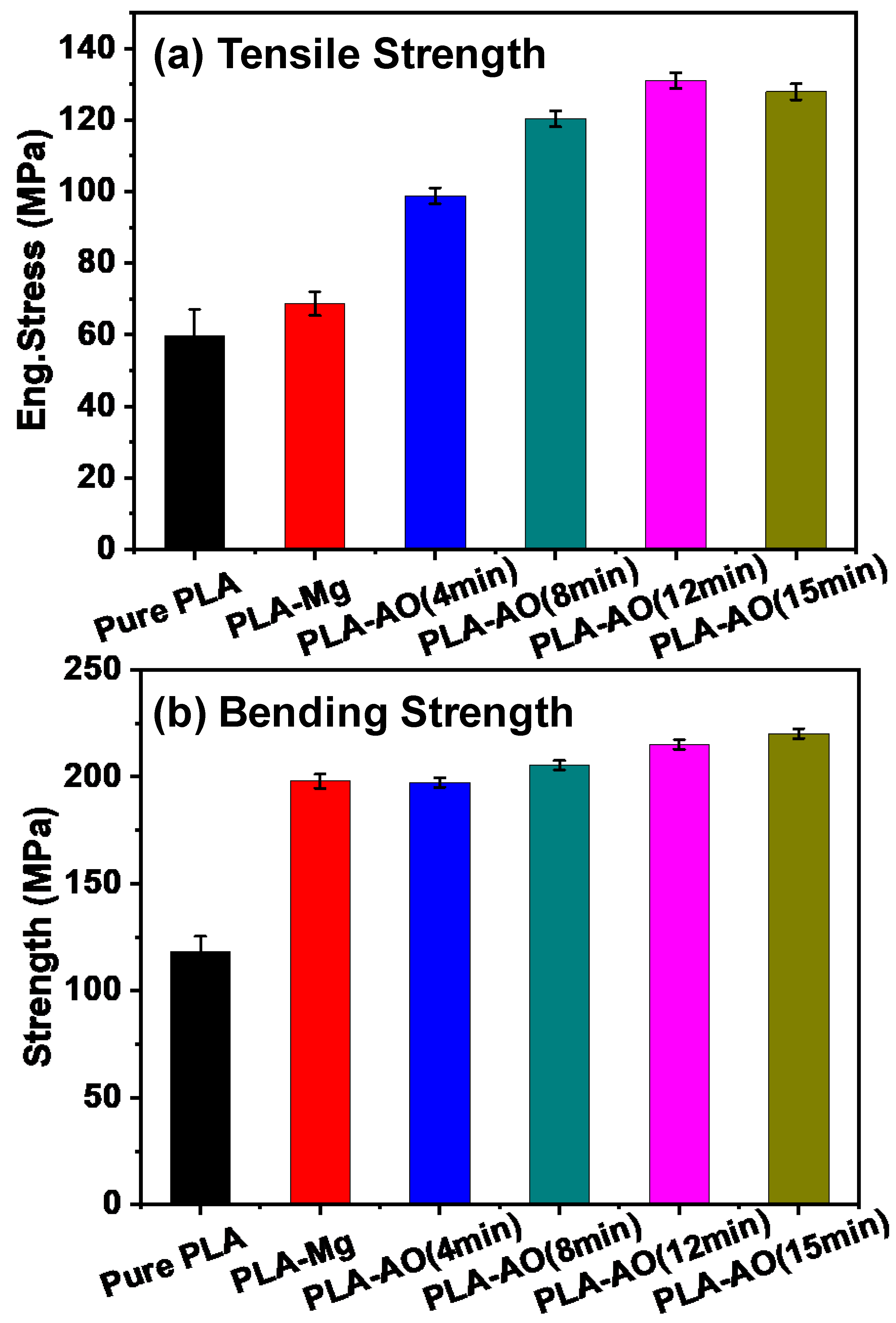
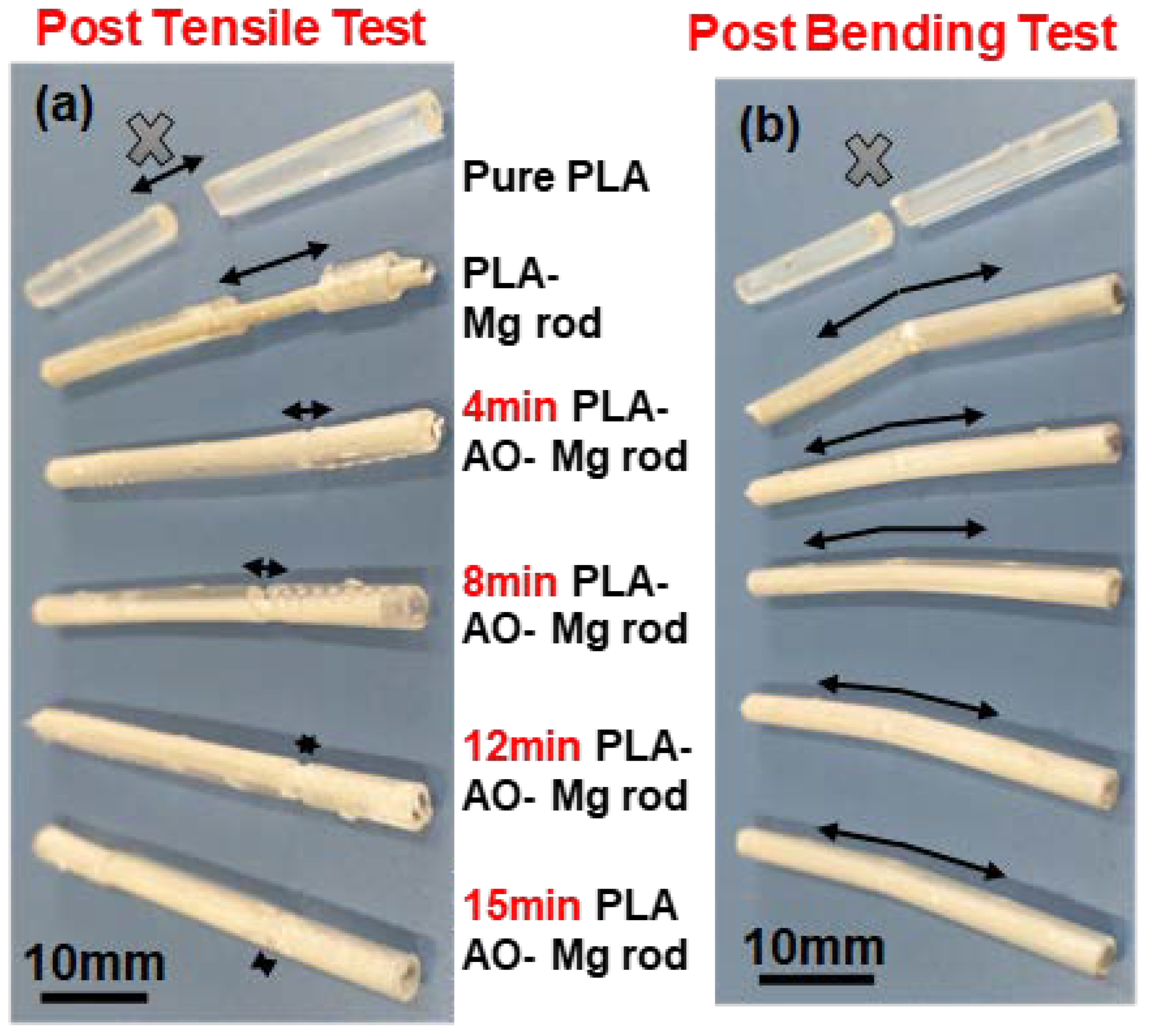
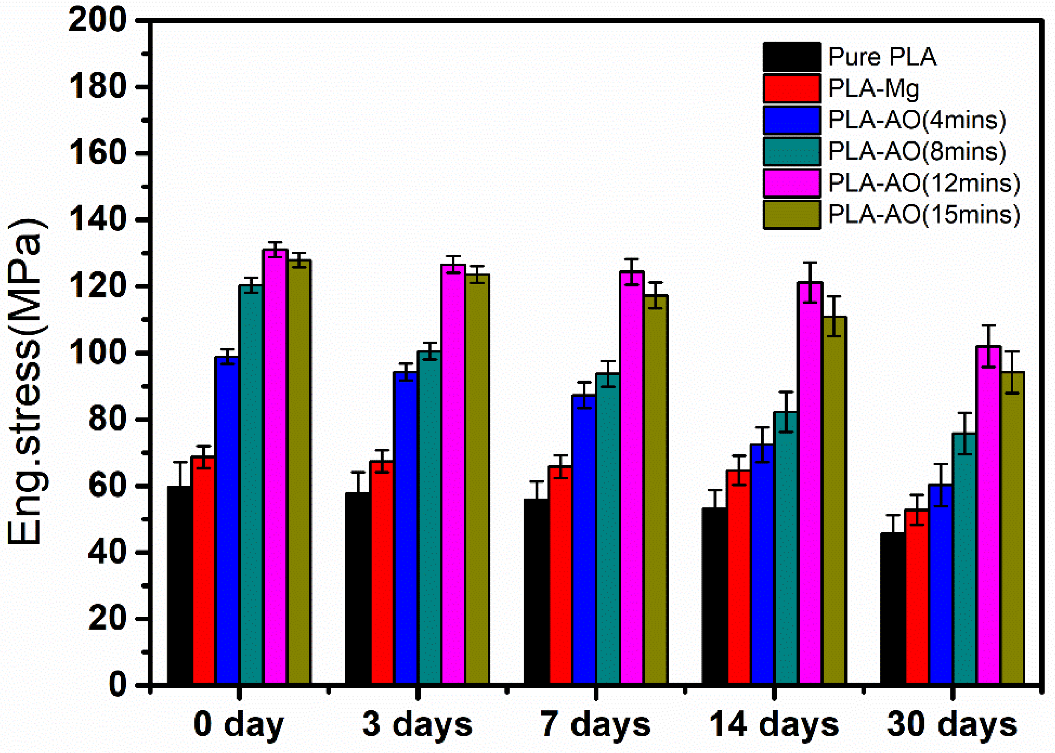
3.2. Mechanical Properties

Bending tests and tensile tests were conducted to evaluate the mechanical properties and the joinability of PLA surface layer and MgO (inner layer) of the PLA-clad Mg rods. The tensile strength of composite rods is shown in Figure 5a, where the pure PLA is included as a comparison. In tensile analysis, pure PLA rod showed the strength of ~60 MPa. Whereas, composite rods revealed the fracture of PLA surface coating before Mg rod inner structure, hence, ultimately progressing towards the material’s failure, as shown in Figure 6a. Consequently, the ultimate tensile strengths of the Mg–PLA rods and Mg–AO–PLA rods at 4, 8, 12 and 15 min were about 69, 99, 120, 131 and 128 MPa, respectively. Hence, it can be concluded that Mg rods inserted PLA had a higher ultimate tensile strength than that of pure PLA. Furthermore, the increase in the tensile strengths of AO treated magnesium alloy rod compared to untreated Mg rods suggests that MgO film had a significant influence in refining the mechanical properties. The bending strength values of the PLA-clad Mg rods are presented in Figure 5b. During three points bending measurement, a simple PLA rod was tested to ultimate failure demonstrating the strength of ~118 MPa. In contrast, only the PLA outer surface was fractured for the composite rods, as shown in Figure 6b. Further, bending strength of composite samples; Mg–PLA rod and Mg–AO–PLA rods at 4, 8, 12 and 15 min was also analyzed. The resultant curves relating to strength-failure was approx. 198, 202, 205, 215 and 220 MPa respectively.

3.3. Degradation Behavior

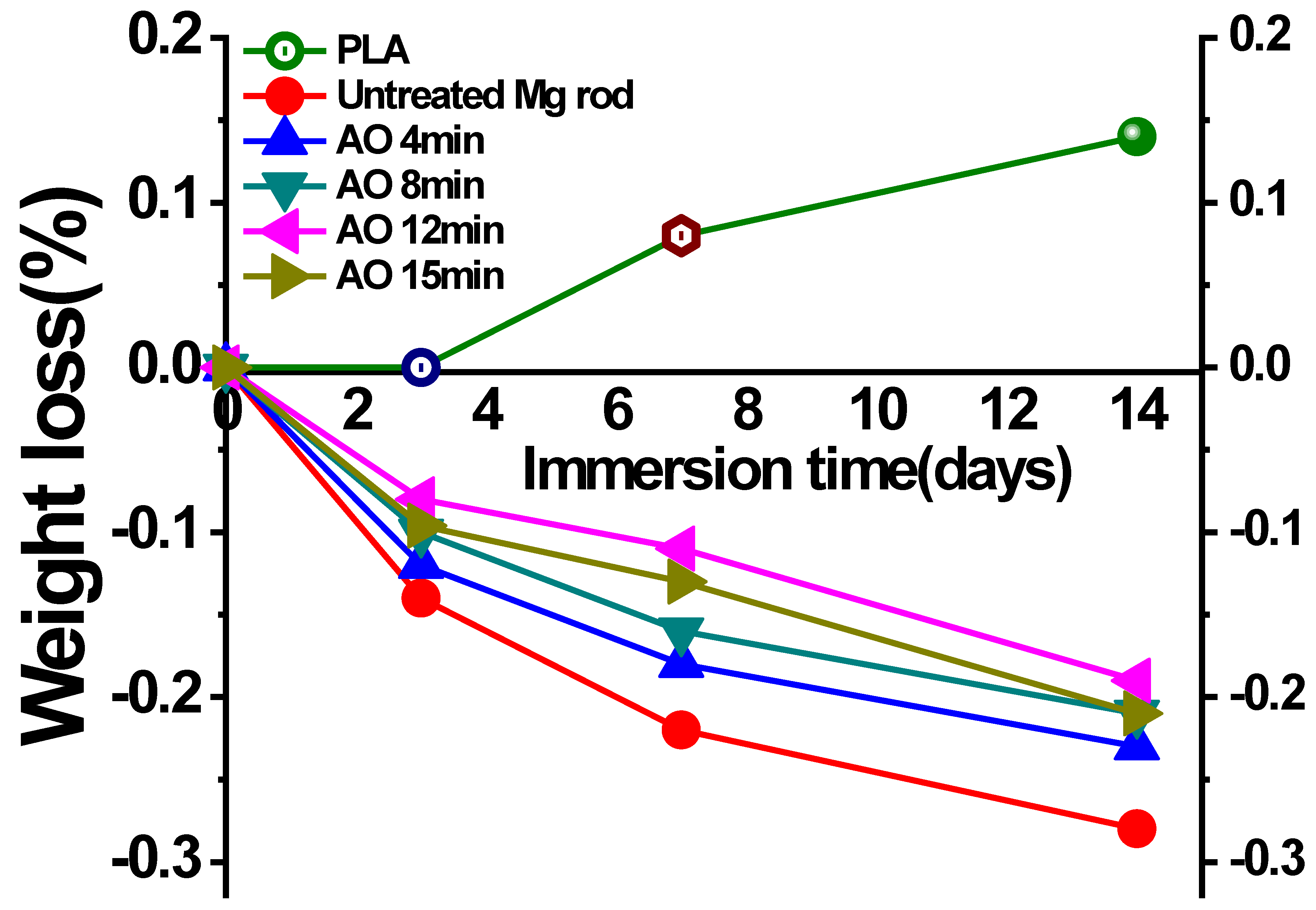
3.3.1. Weight Loss Test

Figure 7 shows the mass variation of the four composites and the pure PLA after 3, 7 and 14 days immersed in Hank’s solution. For pure polylactic acid (PLA), the weight loss was not sufficiently decreased, (0.14%) while soaking for 14 days. The degradation and corrosion behavior of the composite materials prepared with treated and untreated magnesium alloy were also observed. The treated magnesium alloy rod was coated with AO at various oxidation time periods 4, 8, 12 and 15 min. During the process of degradation of the coated sample, Mg(OH)2 was hydrolyzed by Mg matrix and MgO, which sufficiently increased the weight. Moreover, the outer protective effect of polylactic acid, the corrosion product is difficult to enter the solution with the increases of immersion time. Therefore, a corrosion product was accumulated and the sample weight increased. Due to the small change of the weight of polylactic acid, the weight of the composite increased with the increasing effect of polylactic acid and magnesium alloy. For the untreated magnesium alloy, the composite material had no protective effect on the film, the corrosion was relatively severe, the corrosion product was accumulated and the weight increased. The weight gain rate was 0.28% after soaking for 14 days. The magnesium alloy with surface treatment results in high corrosion resistance due to the effect of the oxide layer. The weight gain of Mg–AO–PLA rods treated at 4, 8, 12 and 15 min was 0.22%, 0.20%, 0.14% and 0.15%, respectively, after 14-days immersion. The results indicate that the composites improved corrosion resistance properties with anodizing coating.

3.3.2. Hydrogen Evolution
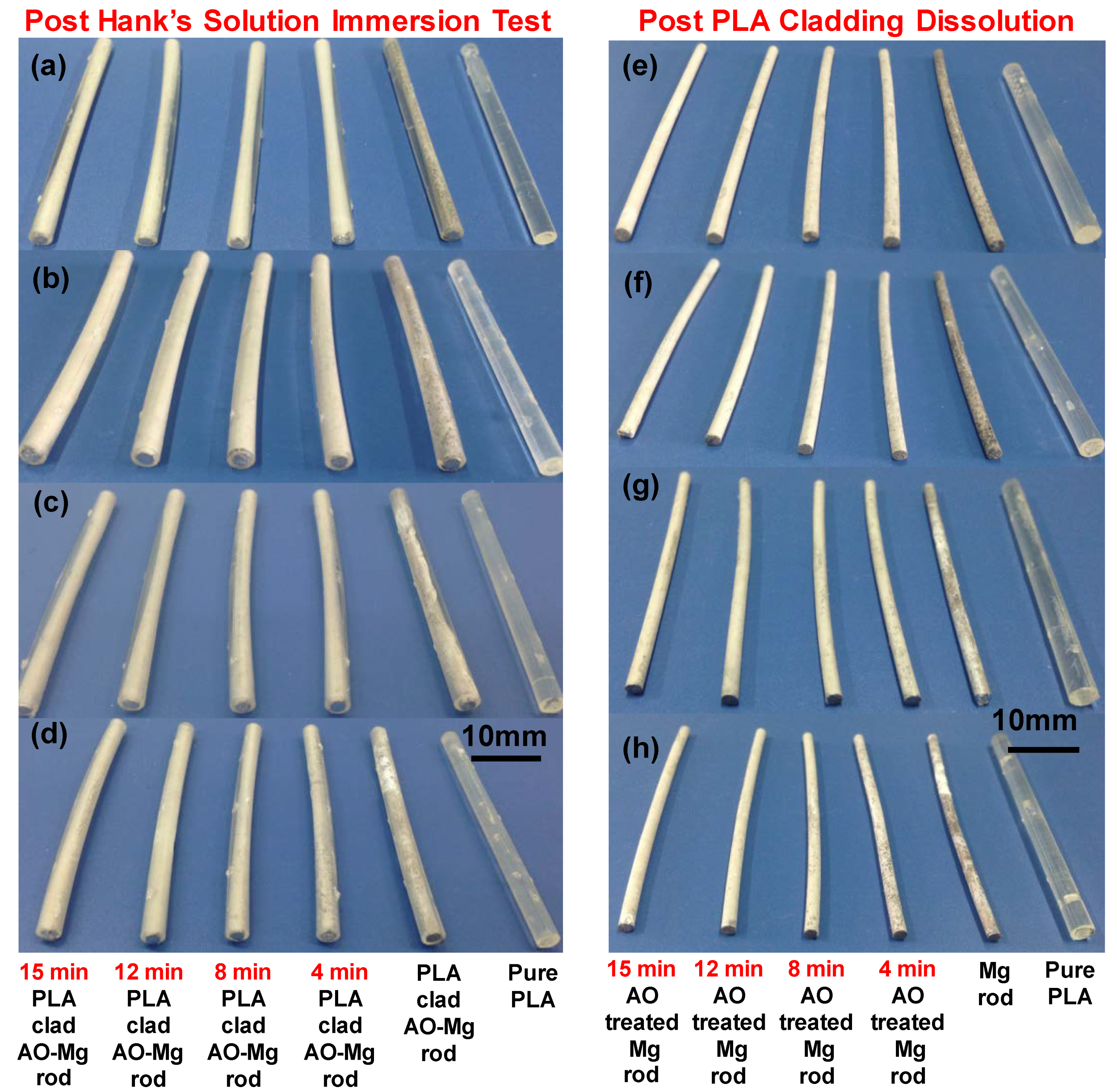
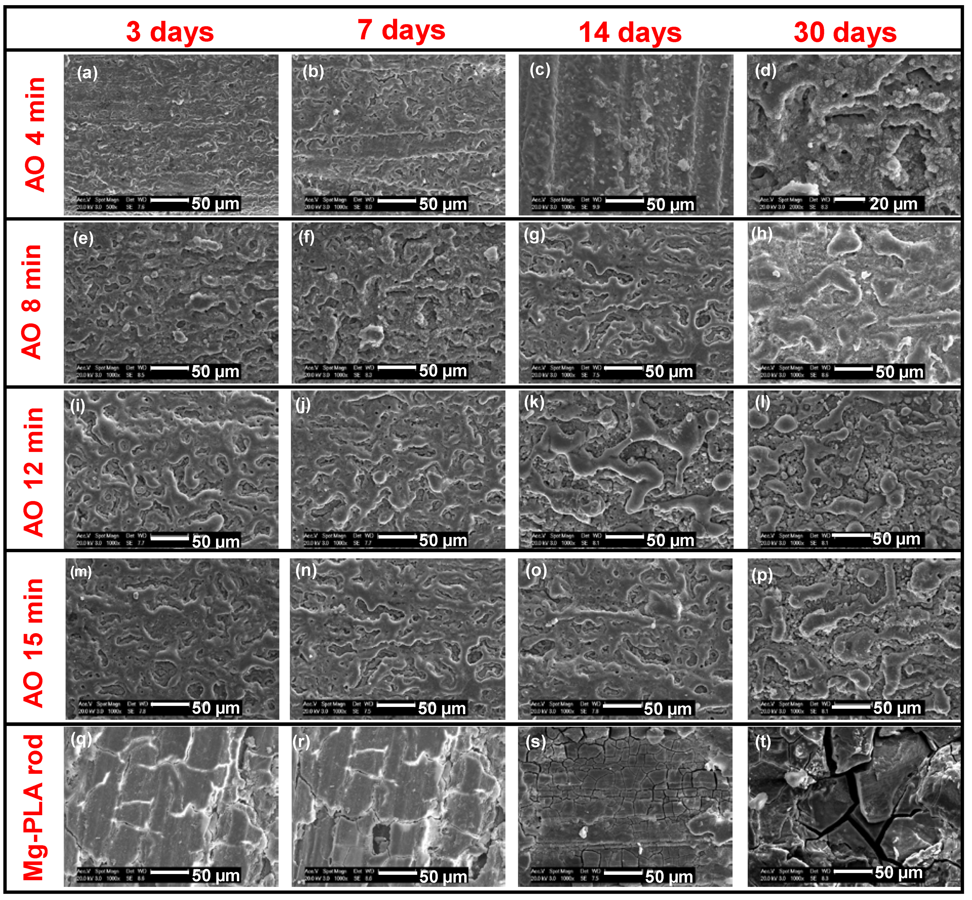
Hydrogen evolution test of samples involved uncoated Mg rods, Mg–AO rods, Mg–PLA rods and Mg–AO–PLA rods; Mg rods treated with AO at 12 min, were selected, soaked in Hank’s solution, and subsequently subjected to observe their degradation behavior. The Mg treated with AO at various oxidation times of 4,8,12 and 15 min showed similar results in evolved hydrogen. Figure 8 shows the amount of the volumes of hydrogen evolved for each immersion as a function of immersion time for 14 days. At the beginning of immersion, numerous bubbles were observed forming over the surface of the Mg rod. No bubbles appeared over the surface of the PLA-clad samples indicating an enhancement in corrosion protection behavior of the outer PLA layer on the inner Mg substrate.
For Mg–AO rods, the hydrogen evolution levels were intermediate between Mg–PLA composite rods and Mg rods. It also showed a change in extending the immersion time. Moreover, the curves showed a decline in the hydrogen evolution rate with respect to the immersion time for Mg–AO rods and Mg rods. This trend can be caused by the production of uniform corrosion species leading to a reduction in the Mg corrosion rate. During the initial 7 days of immersion of Mg–PLA, there was a gradual increment in the hydrogen evolution volume. However, with an increase in the soaking time, the hydrogen evolution rate was also enhanced. This shows that the single layer of PLA provides limited protection. As the distance between Mg and PLA gradually increased, the corrosive intermediate species began to interact with the substrate, leading to the degradation of substrate by corrosion. The curves for hydrogen evolution rate for the Mg–AO–PLA were quite flat, and their hydrogen evolution volume was recorded to be 0.5 mL/cm2 after two weeks of immersion. It could be inferred that the composite material coatings may increase the life span of Mg alloy through corrosion protection.

3.3.3. Morphologies

Figure 9a–d depicts the optical images of the Mg–PLA and Mg–AO–PLA rods after three days, one week, two weeks and one month of immersion time. There was severe degradation of the Mg–PLA rod after an immersion for 14 days, suggesting extreme corrosion. This situation increased in severity after prolonging the immersion time in Hank’s solution. On the other hand, Mg–AO–PLA had a slower degradation rate. It can be concluded that an intermediate coating of MgO can efficiently diminish the rapid and severe corrosion of sample rod.
When the rods were exposed to dichloromethane solution, the PLA claddings separated from the inner surface. A optical macroscopic view of the morphologies of Mg rod surface after PLA elimination is presented in Figure 9e–h. The images depict that uncoated AO-Mg rod samples exhibited extreme corrosion in comparison to the AO coated rods. As the immersion time continued, a non-coated sample allowed the water molecules to penetrate into the PLA matrix, and this caused a degradation of the material.
Figure 10 shows the SEM of the sample with magnified surface morphologies of PLA and corrosion species after removing PLA layer by Dichloromethane dissolution. The column from top to bottom shows Mg–AO–PLA at different AO treatment time periods, along with Mg–PLA composite rods after removal of PLA coating. The images in the row moving from left towards right show the immersion time for 3, 7, 14 and 30 days. Furthermore, after 3 days of immersion time of the Mg–PLA rod, the PLA-removed Mg rod surface showed more rough and fractured structures (Figure 10q). Longer immersion time led to the formation of a uniform corrosion layer. Although the surface was smooth again, shrinkage cracks could still be observed on the surface of the dried sample (Figure 10r–t). Meanwhile, for the PLA removed AO coated Mg rods (Figure 10a–p), prolonged immersion led to the replacement of actual pores with the comparatively smoother surface with a few minute cracks. It could be related to the deposition of corrosion species in open pores and the erosive degradation of MgO ceramic coating over the rod surface.
After the degradation of the aforementioned six sample types in Hank’s solution, their mechanical stability was assessed by computing their tensile and bending strength after 3, 7, 14 and 30 days of immersion. Figure 11 shows the results of tensile test on 7-day-immersed Mg rods treated with AO at 4 min. Prolonging the immersion time influenced the interfacial micro-anchoring mechanism between the MgO layer and PLA, causing its weakening and complete disappearance as shown in Figure 10a–d, due to an exceptional reduction in their binding capacity. Hence, the ultimate strength of pure Mg–AO–PLA rod treated for 4 min results in a rapid drop in tensile strength, from ~99 to ~61 MPa. Pure Mg–AO–PLA rod treated at 8, 12 and 15 min exhibited a slower decline in tensile strength, from ~121 to ~75 MPa, ~132 to ~103 MPa and ~128 to ~95 MPa, respectively, after a 30 days immersion. On the other hand, the ultimate strength of PLA-clad Mg rods had severe cracks with rough surface features (Figure 10q–t), indicating a decrease in the adhesive capacity between the PLA/Mg, because of the corrosion on the Mg rod. The ultimate tensile strength of pure PLA–Mg rod ranged from ~69 to ~53 MPa after 30 days. Since pure PLA has very slow degradation in Hank’s solution, it had the least reduction of tensile strength among all research samples. Nonetheless, the ultimate strength of pure PLA was by far the lowest during the entire degradation interval, measured to be ~46 MPa after immersion for 30 days.
Figure 12 shows the bending strength for the test samples with respect to the immersion time are the results made it evident that the MgO layer formed by anodizing treatment on Mg substrate, enhanced the bending strength as compared to the PLA–Mg rod and pure PLA rod for the entire degradation interval of 30 days. Figure 10d–p indicates the effect of prolonged immersion time. The porous MgO coating smoothed out eventually with a reduction in the interfacial micro-anchorage between the PLA and MgO layer followed by its complete disappearance, inducing a notable drop in their binding capacity. After 30 days, the bending strengths of Mg–AO–PLA rod decreased from ~203 to ~154 MPa, ~206 to ~170 MPa, ~216 to ~173 MPa and ~221 to ~175 MPa when treated at 4, 8, 12 and 15 min, respectively. By contrast, the pure PLA and the PLA–Mg composite rods exhibited a gradual decrease in the bending strength versus immersion time. With the initial values of ~118 MPa, pure PLA had the bending strength values of ~69 MPa after a 30-day immersion in Hank’s solution, indicating a decent strength retention capability. This observation is further justified by the consolidation of the Mg rod cladded with PLA. The ultimate bending strength of pure PLA–Mg rod is from ~198 MPa to ~135 MPa as a result of immersion for 30 days.
The increase in the strength of retention can be due to the AO, which maintains the binding and integrity of the reinforced PLA in immersion conditions. AO-coated portions with no apparent corrosion patterns on the Mg rod following immersion are shown in Figure 10j–p. Therefore, pure Mg–AO–PLA rods treated at 15 min showed a delayed decrease in bending strength, from ~221 MPa to ~175 MPa after 30 days of immersion. It can be interpreted from the results that the interfacial properties played an effective role in modulating the mechanical behavior of the PLA–Mg rod due to immersion degradation. The micro-anchorage between PLA and AO induced porous MgO layer will considerably improve their binding strength, and thus holds a prospect for fixation of bone fractures and various biomedical applications. However, the results indicated the weakening of the micro-anchoring interaction of the corrosion and smoothening of the porous surface due to depletion in corrosive medium, causing a drop in the mechanical properties. Therefore, it is desirable and recommended to improve the PLA–Mg composite rod design with stable porous surface and improved corrosion resistance with better outer protecting surface of PLA.

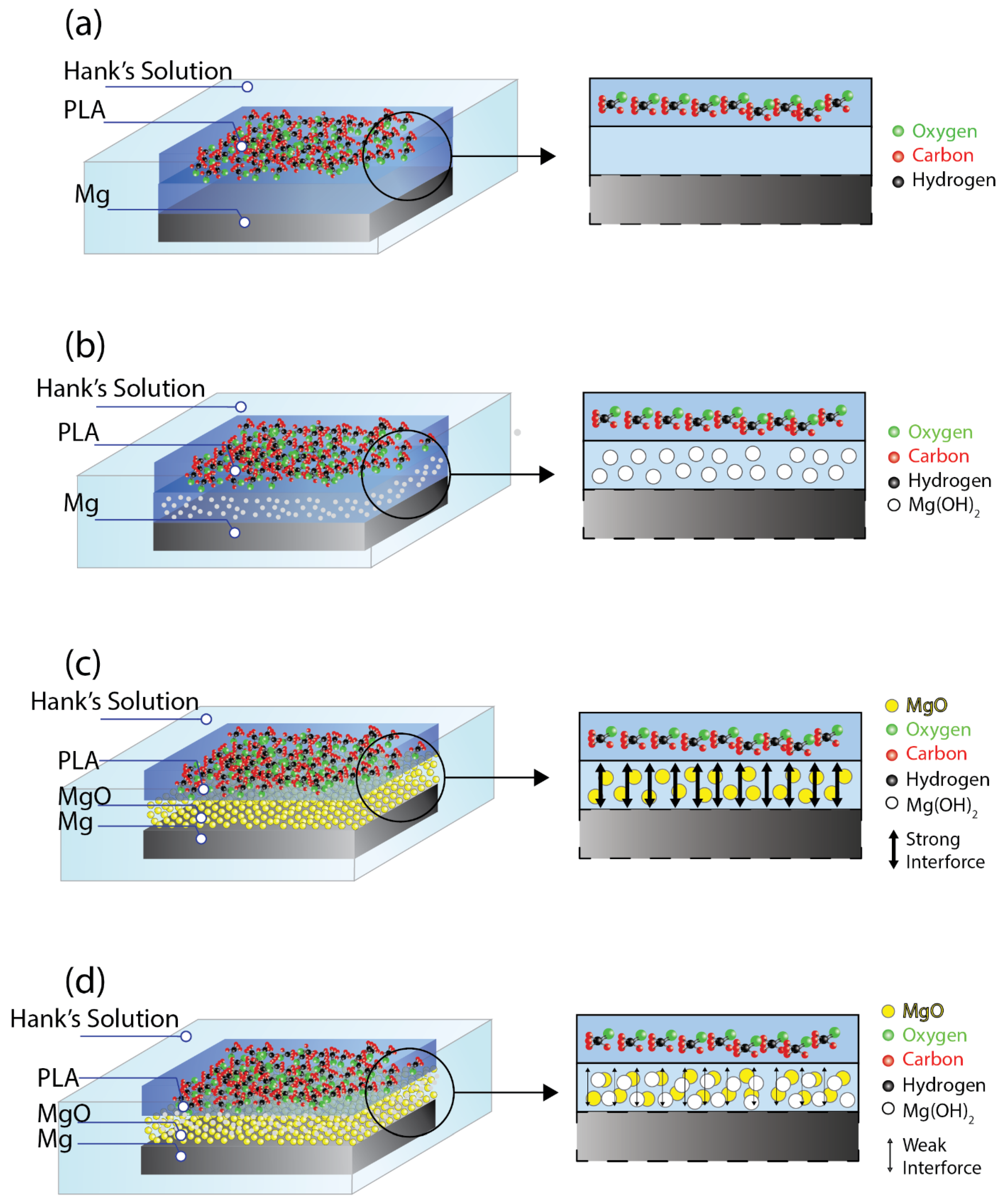
3.4. The Degradation Mechanism

For PLA-clad composite rod, the outermost polylactic acid matrix may protect the magnesium alloy reinforcements during soaking. When the water molecules and erosive ions in the solution reach the surface of the composites rod, the outer polylactic acid plays an effective barrier to the shielding effect. Polylactic acid mainly degrades in four stages: water absorption, ester breakage, soluble oligomer diffusion and dissolution. When the water molecules and corrosive ions in the solution enter through the polylactic acid to the internal magnesium alloy, corrosion of magnesium alloys will occur. The schematic diagram of the degradation process of PLA/Mg is shown in Figure 13a,b. At the initial stage of soaking, the etching solution was blocked on the PLA surface (Figure 13a) due to the protective effect of the outermost PLA. As the soaking time increased, the etching solution passes through the polylactic acid and reaches the interface between the magnesium alloy and the polylactic acid (Figure 13b); as the surface is untreated, the corrosion starts when the etching solution reaches through the polylactic acid and is uniformly corroded at these locations. The degradation products on the surface of Mg rod in the composite are Mg, O, P, C and Ca. The treated surface with the anodizing has a porous structure. The porous structure is indicated with yellow sphere color is shown in Figure 13c,d. With the prolongation of soaking time, the polylactic acid at the pores is degraded and of Mg(OH)2 accumulate at the pores. The corrosion range is expanded horizontally (Figure 13d). At this time, due to the corrosion of the products and destruction of the polylactic acid in the pores, the mechanical locking between the layer and the polylactic acid is weakened, results in the decrease of the interfacial bonding strength and mechanical properties of the composite material. In the whole process of failure, the interfacial adhesion plays a leading role and therefore, no serious corrosion of magnesium alloy.
As per the results, the interfacial characteristics have a significant effect on the mechanical properties of PLA–Mg rods prior to and after the immersion induced decomposition. The micro-anchorage between PLA and AO induced porous MgO layer will considerably improve their binding strength, and thus holds a future prospect for the fixation of bone fractures and various biomedical applications. However, the results indicate the weakening of the micro-anchoring interaction because of the corrosion and smoothening of the porous surface due to depletion in the corrosive medium due to a drop in mechanical properties. Therefore, it is desirable and recommended to improve the PLA–Mg composite rod design with stable porous surface and improved corrosion resistance with better outer protecting surface of PLA.

4. Conclusions

The focus of this study was the preparation of PLA–Mg biodegradable composite rods by plastic injection molding (PIM) techniques for prospective utilization in bone fracture fixation. The following conclusions were drawn from the experimental results:
(1) Mg AZ31 rod surface was treated by anodizing at different time periods of 4, 8, 12 and 15 min. The most compact film was developed on the surface of the magnesium alloy by 12 min of anodization with a coating thickness of 8 µm.
(2) AO coatings substantially enhanced the interfacial linkage between outer PLA coat and the inner Mg rod as an outcome of micro-anchorage. Consequently, this sample with intermediate coating exhibited greater tensile and bending strength values, along with improved resistance to corrosion in Hank’s solution than the PLA–Mg rod without AO treatment.
(3) Mg surfaces treated at 12 min displayed overall better corrosion resistance and mechanical properties in Hank’s solution than other treated surfaces.
(4) A rapid decline in tensile and bending strength was observed for the PLA–Mg rods due to the corrosion and smoothening of the intermediate coating after prolonger immersion in Hank’s solution.

Author Contributions

Conceptualization, M.S.B.; methodology, M.S.B. and M.A.U.; formal analysis, M.S.B., M.A.U., R.A.M., I.M.A., and H.A.; investigation, M.S.B., M.S., R.A.M., I.M.A., and H.A.; writing—original draft preparation, M.S.B., A.M. and M.S.; writing—review and editing, M.S.B., A.M. and M.S.; supervision, M.S.B. All authors have read and agreed to the published version of the manuscript.

Funding

This research received no external funding.

Conflicts of Interest

The authors declare no conflict of interest.

References

  1. Moravej, M.; Mantovani, D. Biodegradable metals for cardiovascular stent application: Interests and new opportunities. Int. J. Mater. Sci. 2011, 12, 4250–4270. [Google Scholar] [CrossRef] [PubMed] [Green Version]
  2. Kunjukunju, S.; Roy, A.; Ramanathan, M.; Lee, B.; Candiello, J.E.; Kumta, P.N. A layer-by-layer approach to natural polymer-derived bioactive coatings on magnesium alloys. Acta Biomater. 2013, 9, 8690–8703. [Google Scholar] [CrossRef] [PubMed]
  3. Gray-Munro, J.E.; Seguin, C.; Strong, M. Influence of surface modification on the in vitro corrosion rate of magnesium alloy AZ31. J. Biomed. Mater. Res. A 2009, 91, 221–230. [Google Scholar] [CrossRef] [PubMed]
  4. Xu, L.; Yamamoto, A. In vitro degradation of biodegradable polymer-coated magnesium under cell culture condition. Appl. Surf. Sci. 2012, 258, 6353–6358. [Google Scholar] [CrossRef]
  5. Ostrowski, N.; Lee, B.; Roy, A.; Ramanathan, M.; Kumta, P. Biodegradable poly(lactide-co-glycolide) coatings on magnesium alloys for orthopedic applications. J. Mater. Sci. Mater. Med. 2013, 24, 85–96. [Google Scholar] [CrossRef]
  6. Hornberger, H.; Virtanen, S.; Boccaccini, A.R. Biomedical coatings on magnesium alloys—A review. Acta Biomater. 2012, 8, 2442–2455. [Google Scholar] [CrossRef]
  7. Bakhsheshi-Rad, H.R.; Hamzah, E.; Ismail, A.F.; Sharer, Z.; Abdul-Kadir, M.R.; Daroonparvar, M.; Saud, S.N.; Medraj, M. Synthesis and corrosion behavior of a hybrid bioceramic-biopolymer coating on biodegradable Mg alloy for orthopaedic implants. J. Alloys Compd. 2015, 648, 1067–1071. [Google Scholar] [CrossRef]
  8. Li, J.N.; Cao, P.; Zhang, X.N.; Zhang, S.X.; He, Y.H. In vitro degradation and cell attachment of a PLGA coated biodegradable Mg–6Zn based alloy. J. Mater. Sci. 2010, 45, 6038–6045. [Google Scholar] [CrossRef]
  9. Anderson, J.M.; Shive, S.M. Biodegradation and biocompatibility of PLA and PLGA microspheres. Adv. Drug Deliv. Rev. 2012, 64, 72–82. [Google Scholar] [CrossRef]
  10. Li, L.; Ding, S.; Zhou, C. Preparation and degradation of PLA/chitosan composite materials. J. Appl. Polym. Sci. 2004, 91, 274–277. [Google Scholar] [CrossRef]
  11. Li, H.; Chang, J. pH-compensation effect of bioactive inorganic fillers on the degradation of PLGA. Compos. Sci. Technol. 2005, 65, 2226–2232. [Google Scholar] [CrossRef]
  12. Wu, Y.H.; Li, N.; Cheng, Y.; Zheng, Y.F.; Han, Y. In vitro study on biodegradable AZ31 magnesium alloy fibers reinforced PLGA composite. J. Mater. Sci. Technol. 2013, 29, 545–550. [Google Scholar] [CrossRef]
  13. Staiger, M.P.; Pietak, A.M.; Huadmai, J.; Dias, G. Magnesium and its alloys as orthopedic biomaterials: A review. Biomaterials 2006, 27, 1728–1734. [Google Scholar] [CrossRef] [PubMed]
  14. Saris, N.E.L.; Mervaala, E.; Karppanen, H.; Khawaja, J.A.; Lewenstam, A. Magnesium: An update on physiological, clinical and analytical aspects. Clin. Chim. Acta 2000, 294, 1–26. [Google Scholar] [CrossRef]
  15. Yamasaki, Y.; Yoshida, Y.; Okazaki, M.; Shimazu, A.; Kubo, T.; Akagawa, Y.; Uchida, T. Action of FGMgCO3 Ap-collagen composite in promoting bone formation. Biomaterials 2003, 24, 4913–4920. [Google Scholar] [CrossRef]
  16. Mueller, W.D.; Nascimento, M.L.; Mele, D.; Lee, M.F. Critical discussion of the results from different corrosion studies of Mg and Mg alloys for biomaterial applications. Acta Biomater. 2010, 6, 1749–1755. [Google Scholar] [CrossRef]
  17. Xin, Y.; Hu, T.; Chu, P.K. Influence of test solutions on in vitro studies of biomedical magnesium alloys. J. Electrochem. Soc. 2010, 157, 238–243. [Google Scholar] [CrossRef]
  18. Mathew, A.P.; Oksman, K.; Sain, M. Mechanical properties of biodegradable composites from poly lactic acid (PLA) and microcrystalline cellulose (MCC). J. Appl. Polym. Sci. 2005, 97, 2014–2025. [Google Scholar] [CrossRef]
  19. Cifuentes, S.C.; Gavilán, R.; Lieblich, M.; Benavente, R.; González-Carrasco, J.L. In vitro degradation of biodegradable polylactic acid/magnesium composites: Relevance of Mg particle shape. Acta Biomater. 2016, 32, 348–357. [Google Scholar] [CrossRef]
  20. Song, Y.W.; Shan, D.Y.; Han, E.H. Electrodeposition of hydroxyapatite coating on AZ91D magnesium alloy for biomaterial application. Mater. Lett. 2008, 62, 3276–3279. [Google Scholar] [CrossRef]
  21. Li, L.; Gao, J.; Wang, Y. Evaluation of cyto-toxicity and corrosion behavior of alkali-heat-treated magnesium in simulated body fluid. Surf. Coat. Technol. 2004, 185, 92–98. [Google Scholar] [CrossRef]
  22. Chiu, K.Y.; Wong, M.H.; Cheng, F.T.; Man, H.C. Characterization and corrosion studies of fluoride conversion coating on degradable Mg implants. Surf. Coat. Technol. 2007, 202, 590–598. [Google Scholar] [CrossRef]
  23. Sealy, M.P.; Guo, Y.B. Surface integrity and process mechanics of laser shock peening of novel biodegradable magnesium–calcium (Mg–Ca) alloy. J. Mech. Behav. Biomed. Mater. 2010, 3, 488–496. [Google Scholar] [CrossRef] [PubMed]
  24. Blawert, C.; Dietzel, W.; Ghali, E.; Song, G. Anodizing treatments for magnesium alloys and their effect on corrosion resistance in various environments. Adv. Eng. Mater. 2006, 8, 511–533. [Google Scholar] [CrossRef]
  25. Ren, M.; Cai, S.; Liu, T.; Huang, K.; Wang, X.; Zhao, H.; Niu, S.; Zhang, R.; Wu, X. Calcium phosphate glass/MgF2 double layered composite coating for improving the corrosion resistance of magnesium alloy. J. Alloys Compd. 2014, 591, 34–40. [Google Scholar] [CrossRef]
  26. Li, N.; Zheng, Y. Novel magnesium alloys developed for biomedical application: A review. J. Mater. Sci. Technol. 2013, 29, 489–502. [Google Scholar] [CrossRef]
  27. Li, X.; Chu, C.L.; Liu, L.; Liu, X.K.; Bai, J.; Guo, C.; Xue, F.; Lin, P.H.; Chu, P.K. Biodegradable poly-lactic acid based composite reinforced unidirectionally with high-strength magnesium alloy wires. Biomaterials 2015, 49, 135–144. [Google Scholar] [CrossRef]
  28. Butt, M.S.; Bai, J.; Wan, X.; Chu, C.; Xue, F.; Ding, H.; Zhou, G. Mechanical and degradation properties of biodegradable Mg strengthened poly-lactic acid composite through plastic injection molding. Mater. Sci. Eng. C 2017, 70, 141–147. [Google Scholar] [CrossRef]
  29. Cai, H.; Zhang, Y.; Meng, J.; Li, X.; Xue, F.; Chu, C.; Bai, J. Enhanced fully- biodegradable Mg/PLA composite rod: Effect of surface modification of Mg-2Zn wire on the interfacial bonding. Surf. Coat. Technol. 2018, 350, 722–731. [Google Scholar] [CrossRef]
  30. Butt, M.S.; Bai, J.; Wan, X.; Chu, C.; Xue, F.; Ding, H.; Zhou, G. Mg alloy rod reinforced biodegradable poly-lactic acid composite for load bearing bone replacement. Surf. Coat. Technol. 2017, 309, 471–479. [Google Scholar] [CrossRef]
  31. Hanks, J.H.; Wallace, R.E. Relation of oxygen and temperature in the preservation of tissues by refrigeration. Proc. Soc. Exp. Biol. Med. 1949, 71, 196–200. [Google Scholar] [CrossRef]
  32. Tkacz, J.; Slouková, K.; Minda, J.; Drábiková, J.; Fintová, S.; Doležal, P.; Wasserbauer, J. Influence of the composition of the Hank’s balanced salt solution on the corrosion behavior of AZ31 and AZ61 magnesium alloys. Metals 2017, 7, 465. [Google Scholar] [CrossRef] [Green Version]
  33. Zhang, C.Y.; Zeng, R.C.; Liu, C.L. Comparison of calcium phosphate coatings on Mg–Al and Mg–Ca alloys and their corrosion behavior in Hank’s solution. Surf. Coat. Technol. 2010, 204, 3636–3640. [Google Scholar]
  34. Maqbool, A.; Hussain, M.A.; Khalid, F.A.; Bakhsh, N.; Hussain, A.; Kim, M.H. Mechanical characterization of copper coated carbon nanotubes reinforced aluminum matrix composites. Mater. Char. 2013, 86, 39–48. [Google Scholar] [CrossRef]
  35. Saleem, M.; Hwan, L.D.; Kim, I.; Kim, M.S.; Maqbool, A.; Nisar, U.; Pervez, S.A. Revealing of core shell effect on frequency-dependent properties of Bi-based relaxor/ferroelectric ceramic composites. Sci. Rep. 2018, 8, 14146. [Google Scholar] [CrossRef] [PubMed]
  36. Saleem, M.; Butt, M.S.; Maqbool, A.; Umer, M.A.; Shahid, M.; Javaid, F.; Malik, R.A.; Jabbar, H.; Khalil, H.M.W.; Hwan, L.D.; et al. Percolation phenomena of dielectric permittivity of a microwave-sintered BaTiO3–Ag nanocomposite for high energy capacitor. J. Alloys Compd. 2020, 822, 153525. [Google Scholar] [CrossRef]
  37. Kotsikos, G.; Sutcliffe, J.M.; Holroyd, N.J.H. Hydrogen effects in the corrosion fatigue behaviour of the white zone of 7xxx series aluminium alloy welds. Corr. Sci. 2000, 42, 17–33. [Google Scholar] [CrossRef]
  38. Alabbasi, A.; Liyanaarachchi, S.; Kannan, M.B. Polylactic acid coating on a biodegradable magnesium alloy: An in vitro degradation study by electrochemical impedance spectroscopy. Thin Solid Films 2012, 520, 6841–6844. [Google Scholar] [CrossRef]
Figure 1. Prepared samples: (a) anodized (AO)-Mg rods treated at 4, 8, 12 and 15 min Mg and pure polylactic acid (PLA) rods (b) PLA-clad AO-treated 4, 8, 12 and 15 min Mg rods, PLA-clad Mg and pure PLA rods.
Crystals 10 00381 g001
Figure 2. Surface morphology of AO coatings produced at various time intervals (a) 4 min, (b) 8 min, (c) 12 min and (d) 15 min.
Crystals 10 00381 g002
Figure 3. SEM images of cross-sectional of composites rod after treatment with anodizing: (a) PLA-clad AO-treated Mg rod at 4 min, (b) 8 min, (c) 12 min, (d) 15 min (e) PLA–Mg rod, (uncoated) and (f) starting Mg rod. The dotted line is only added for the guide for eye and representing the smoothness of the coating where the micro porosity and cracks are indicated by the arrows.
Crystals 10 00381 g003
Figure 4. X-ray diffraction (XRD) patterns of the surface of pure and AO treated Mg rod.
Crystals 10 00381 g004
Figure 5. (a) The ultimate tensile strength and (b) bending strength of composite rods.
Crystals 10 00381 g005
Figure 6. Image of composite rods and pure PLA rod after (a) tensile test and (b) bending test.
Crystals 10 00381 g006
Figure 7. Mass losses as a result of immersion in Hank’s solution.
Crystals 10 00381 g007
Figure 8. Hydrogen evolution dependence on immersion time for various experimental samples in Hank’s solution at 37 °C.
Crystals 10 00381 g008
Figure 9. Images of the experimental composite rods for (a) 3, (b) 7, (c) 14 and (d) 30 days after immersion in Hank’s solution, and composite rods for (e) 3, (f) 7, (g) 14 and (h) 30 days after removal of PLA cladding of immersed rods in Hank’s solution.
Crystals 10 00381 g009
Figure 10. SEM surficial morphologies of the experimental composite rods after removal of PLA and corrosion products where the column from top to bottom corresponds to Mg–AO–PLA at different AO treatment time periods, and Mg–PLA rods after removing PLA layer by dichloromethane dissolution and the row from left to right corresponds to immersion time for 3, 7, 14 and 30 days (scale bar 50 µm in all images).
Crystals 10 00381 g010
Figure 11. Ultimate tensile strength of composite rods and pure PLA rod as a function of immersion time for 30 days.
Crystals 10 00381 g011
Figure 12. Ultimate bending strength of composite rods and pure PLA rod as a function of immersion time for 30 days.
Crystals 10 00381 g012
Figure 13. Schematic diagram of the degradation process of PLA–Mg clad (a) water absorption, (b) ester breakage (c) soluble oligomer diffusion and (d) degradation of PLA and Mg(OH)2 accumulation at the pores.
Crystals 10 00381 g013
Table 1. Plastic injection molding parameters.
MaterialInjection Speed Injection TemperatureCooling TimePressure TimeBacking PressureCylinder Temperature
Mg rod20 mm/s190 °C10 s3 s750 bar200-195-190-185-35 °C

