Article

Illuminance and Starting Distance of the Far Field of LED-Array Luminaire Operated at Short Working Distance

1
Department of Optics and Photonics, National Central University, Zhong-Li 32001, Taiwan
2
Department of Electrophysics, National Chiao Tung University, Hsin-Chu 30010, Taiwan
*
Author to whom correspondence should be addressed.
Crystals 2020, 10(5), 360; https://doi.org/10.3390/cryst10050360
Submission received: 12 March 2020 / Revised: 24 April 2020 / Accepted: 27 April 2020 / Published: 1 May 2020

Abstract

:
A luminaire with a light-emitting diode (LED) array can provide hotspot illumination in a short range. Therefore, a design of a luminaire with the largest central illuminance (LCI) and a high uniformity is warranted. In this paper, we present a study of illuminance variation with respect to the distance of an illumination target of a luminaire with LED array. The emission property of the luminous intensity is characterized by the cosine power law or the divergent angle of full width at half maximum (FWHM). A real LED module is designed to create the simulation for different luminaire types. The occurrence of the LCI and the far-field region are observed. Our results demonstrate that the LCI distance remains shorter than the starting distance of the far field (SDFF). To simplify the simulation, we propose the replacement of the real LED module with a point or flat-extended source. Such light sources must be equipped with the specific cosine power factor corresponding to the divergent angle of the FWHM of the LED module. These light sources are acceptable for describing illumination characteristics, including the SDFF. Our results may facilitate the design of LED-array luminaires operated at short working distances, such as reading lighting or illumination in microscopes.

1. Introduction

Solid-state lighting (SSL) has been used for the generation of special lighting because of its >100 lm/W luminous efficacy [1,2]. The introduction of the white light emitting diode (LED), with long life, vivid color, energy-saving ability, fast response, and environmental benefit, has led to a revolution in lighting [3,4,5,6,7,8,9,10]. In general, a white LED is fabricated with a blue die covered with a volume containing phosphor and is thus called phosphor-converted white LED (pcW-LED) [2,11,12,13]. The volume containing phosphor is usually a combination of silicone and phosphor. From the perspective of a luminaire or a lamp, the compact size of a pcW-LED enables design freedom, which could be limited when traditional light sources are used. To provide sufficient illuminance with high optical flux emission, an optional design involves the use of a cluster pcW-LED [14]. However, this cluster LED could be too bright for the human eye. Therefore, an LED array in a luminaire can alternatively be used [15,16,17,18,19]. However, a large design freedom can impede some essential illumination properties. At the level of the light source, a designer always handles the luminous intensity. However, for checking a luminaire, one of the most important factors is illuminance uniformity on the illumination target. Therefore, for a luminaire, the illuminance uniformity on the illumination target is potentially more of a straightforward performance measure than the luminous intensity. When the observer is away from the luminaire, the working distance becomes a key issue for illuminance variation. In a certain region, the illuminance varies rapidly, but in some other regions, the illuminance varies gradually. Figure 1 defines regions that are crucial for exhibiting different light field properties. When light is emitted by the active area of the light source, it passes through the microstructure of the light source volume. After the light leaves the light source, the light field becomes scalar, with its location being in the mid-field region, where the light pattern varies in intensity and illuminance from one distance to another [20,21]. When the distance is increased further, such that the luminaire appears small and the light pattern in intensity does not vary with change of distance, the light field locates in the far-field region, where the light pattern in luminous intensity does not vary, but the illuminance changes by inverse-square of the distance [22,23,24,25]. In general, an illumination target should be located in the far-field region for the illuminance to obey the inverse-square law and thus become uniform. However, in most modern devices, such as a table reading lights or a ring LED light in microscope, the distance between the luminaire and its illumination target is not sufficiently long. Therefore, the starting distance of the far field (SDFF) and largest central illuminance (LCI) of an SSL luminaire should be elucidated. In this study, we investigate the illuminance distribution of SSL luminaires with various important factors. The aforementioned SDFF and LCI are also calculated. Our result may facilitate modern SSL luminaire design.

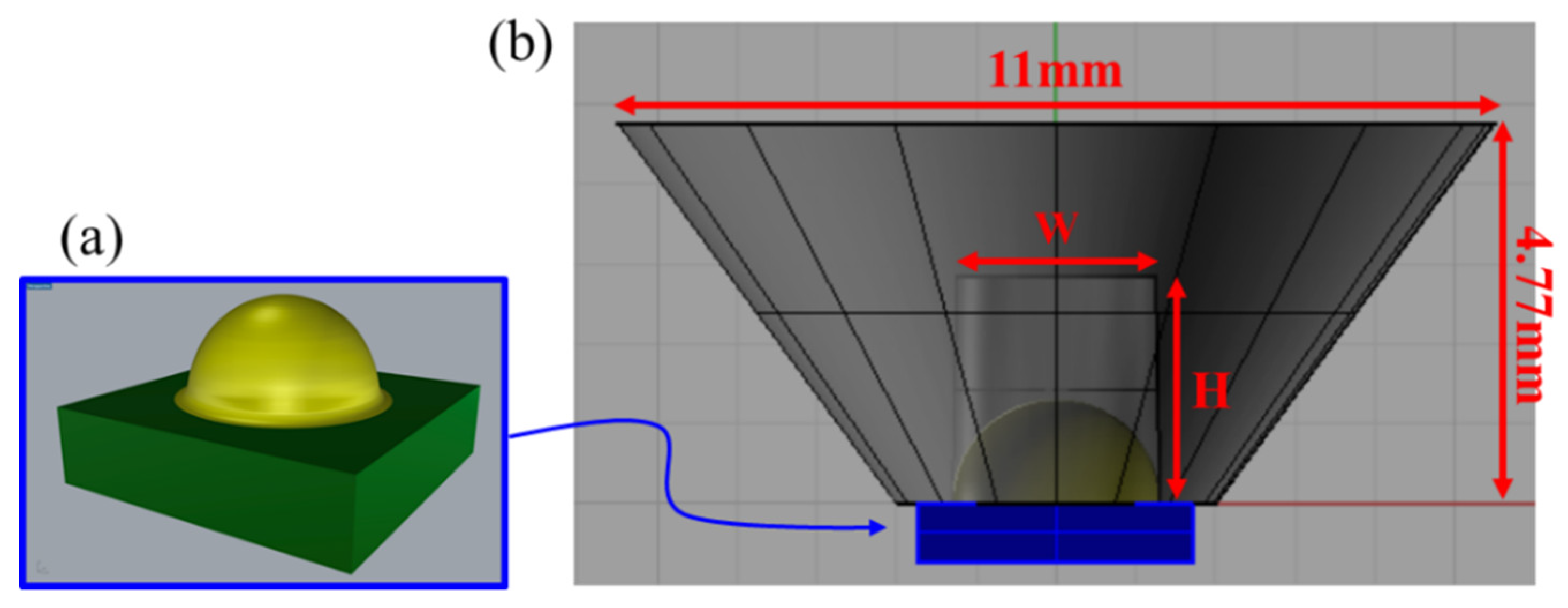
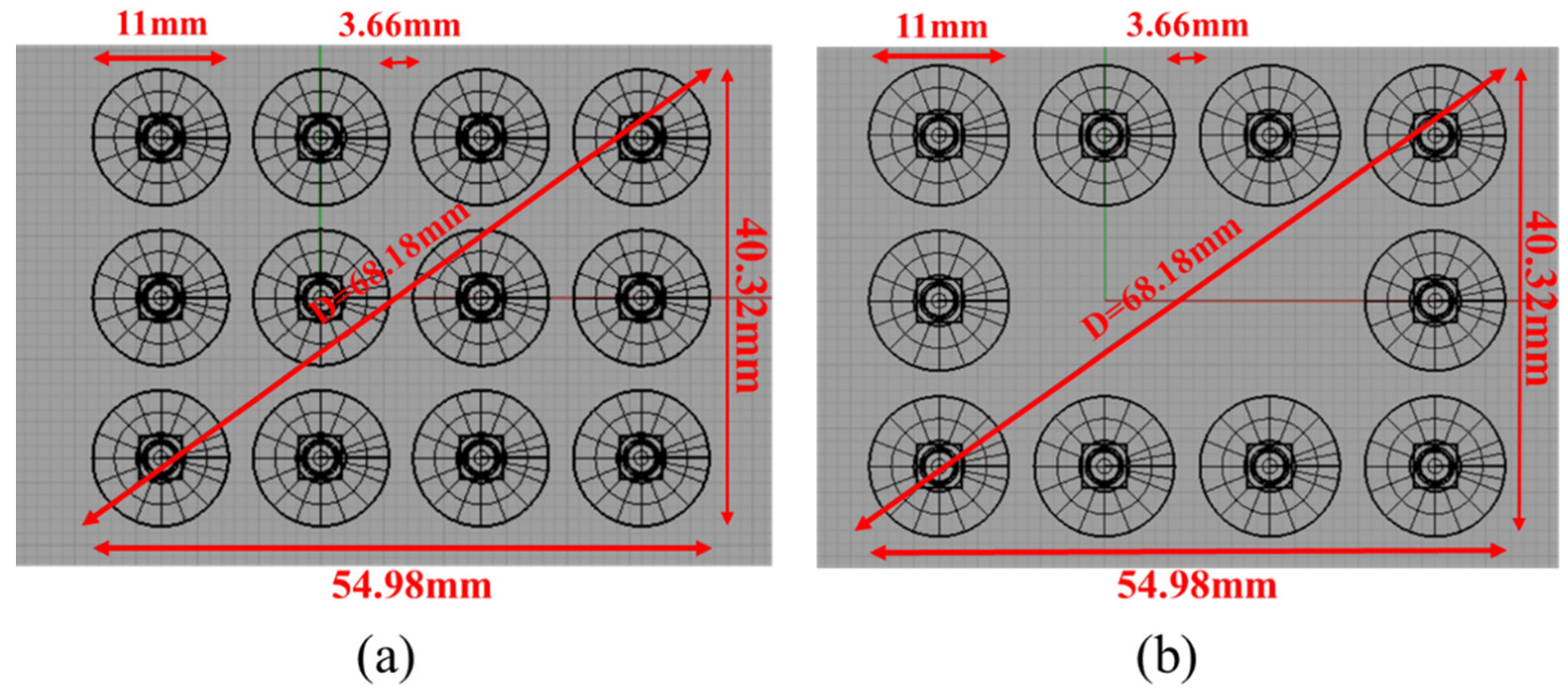
2. Light Source and Luminare

With regard to the light source, pcW-LED is a complicated light source but not a point source. Thus, to figure out the illumination properties of an LED-array luminaire, it could be particularly difficult, and as a result, we may define the illumination property by using the far-field intensity rule:
I ( θ ) = I 0 c o s m ( θ )
where I 0 is the luminous intensity at the normal direction, m is the cosine power factor, and θ is the view angle. Equation (1) will describe a Lambertian light source when m = 1, while m = 0 for a point source, and m approaches infinity when the light is collimated [26]. Its packaging variation leads each pcW-LED to have properties different from those of pcW-LEDs; nevertheless, the value of m remains within 0.5–5. Moreover, rather than the cosine power factor, full width at half maximum (FWHM) would be more suitable for describing the light source here because the actual light pattern is not pure cosine function. Here, the FWHM value is usually used to describe the behavior of spatial intensity distribution of the light source. Figure 2 presents a corresponding table between the cosine power factor and FWHM of a light source.
To accurately describe the illumination property, we begin from a real pcW-LED with an optical component to control the illumination pattern. Figure 3 presents the pcW-LED and the structure of the optical component. The pcW-LED used here is named XP-E, manufactured by CREE [27]. The optical component is a total internal reflection (TIR) lens [28]. The optical flux of XP-E LED is about 129.3 lm at the electric power of 2.38 W. The optical efficiency of TIR lens is about 92%. Therefore, the luminous efficacy of the combination of XP-E LED and the proposed TIR lens is about 50 lm/W. To change the shape of the TIR lens, we produce the light pattern corresponding to a specific cosine power factor. As shown in Figure 3, we fix the top open size 11 mm and the thickness 4.77 mm and adjust W and H. Through precise light source model of XP-E by using a mid-field model [20,21], we can control the divergent angle of the LED module with adjustments of W and H [15]. Thus, we have five LED modules with different FWHM, where the FWHM and the corresponding geometries (FWHM, W, H) of the TIR lens can be listed (30 ° , 2.35, 3.55), (45 ° , 2.5, 2.85), (60 ° , 2.53, 2.05), (80 ° , 2.56, 1.41), and (115 ° , without TIR lens). The geometry of the TIR lens and the corresponding cosine power factors of the four LED modules are illustrated in Figure 4.
To investigate the illumination properties at different observation distances, we constructed two types of luminaires (Figure 5). The first contained a 4 × 3 array of the LED module and we called it the “solid array”. In the second luminaire, the central two modules were removed from the 4 × 3 LED array, and we called it the “hollow array”. Both the luminaires had identical dimensions in all directions, so as to make a fair comparison.

3. Typical and Atypical Illumination Properties

The illumination simulation was performed for the two luminaires on a target plane at different distances. The simulation was made using ASAP (by Breault Research Organization, Inc., Tucson, AZ, USA) [29]. Figure 6 presents the simulation result. The vertical axis represents central illuminance (in lux), whereas the horizontal axis indicates the luminaire-illumination-plane distance. Both axes are in logarithmic scale. For the solid array, the LCI starts at a shorter distance and then decreases as the distance increases. When the distance increases further, the slope of the illuminance approaches a constant value, gradually reaching −2, as illustrated by the definition of the illuminance:
E = I R 2
where E is the illuminance, I is the luminous intensity, and R is the observation distance. Equation (2) for the far-field condition in the logarithmic scale can be represented as:
( log ( E ) Log ( I ) ) / log ( R ) = 2
In this condition, the luminous intensity becomes constant; thus, the illuminance obeys the inverse-square law as the slope reaches −2. Thus, we can calculate the far-field distance in Figure 6 by calculating the slope of the curve.
In the hollow array, we found that the LCI occurs at a longer distance. There are two factors that decide LCI location. The first is the divergent angle of the LED module. The smaller the divergent angle, the longer is the distance. This is applicable to both solid and hollow arrays. The second factor is the geometry of the LED module array. The pcW-LED is a relatively small light source. Therefore, the discrete LED module array forms local hotspot at a short observation distance. The hotspots mentioned in the article refer to the extremely bright spots that cause the light pattern to become non-uniform distribution. Such an atypical light pattern is unacceptable in general lighting. The presence of a hotspot depends on the divergent angle of the light source and spacing among LED modules. As shown in Figure 7 and Figure 8, we can observe hotspots at short observation distance when the divergent angle of the light source module is small. In Figure 7 and Figure 8, the red, blue, and green squares respectively represent the light pattern at the FWHM values of 30, 60, and 80 degrees. Additionally, each color square also has three light patterns for three distances, respectively. Notably, the hollow array provides relatively poor results because the spacing between some LED modules is extended such that it needs a longer distance to merge hotspots. In general, a luminaire is away from the illumination target, when the target is located in the far-field region of the luminaire. However, in lights such as reading lights, a reader could be at a short distance from the luminaire. Therefore, the far-field distance of a luminaire containing different light source arrays warrants elucidation.

4. Simplified Simulation of the Far Field

In general, the far field can be found at a distance 5–10 times that of the luminaire dimension [22,23]. As noted above, we found that far-field distance depends on the divergent angle of the LED module and spacing of the LED array. A more systematic study using a simpler simulation model is warranted. Thus, we attempt to simplify the LED module by using either a point source or a flat-extended source. In these two cases, the far-field divergent angle is set to the same level as that for the LED module. Figure 9 illustrates comparisons among the simulation results of the cases of the LED module (black line), point source (blue dashed line), and flat extended source (red dashed line) at the distances of 10, 50, and 100 mm, respectively. The divergent angle of the light source is set as 30 ° , which will make the similarity worse. Therefore, if the similarity is high enough, the other divergent angles will be good. Normalized cross correlation (NCC) [20,30] between any two curves is >99%; in other words, the point source and flat-extended source are workable compared with the LED module. Thus, deciding the far-field region when developing a luminaire used at a relatively short distance becomes easy.
To find the far field, we examine the variation slope of the central illuminance as a function of distance, all according to Equation (3). When the slope has the maximum error of ±3%, SDFF is −1.94. A ratio between the SDFF (RFF) and the luminaire size (D) with respect to the divergent angle of the three approaches in the two array cases is presented in Figure 10, where SDFF simulation is similar with that of the LED module when the divergent angle is ≤115 ° . Results indicate that SDFF is at most five times that of the luminaire dimension, even when the divergent angle of the hollow array is 30 ° . When the divergent angle is >90 ° , SDFF is only three times that of the luminaire dimension. Figure 11 further illustrates the simulation of the distance for occurrence of the LCI (REmax) in the hollow array. First, despite their LCI being relatively different, the point source and flat-extended source are acceptable for allocating distance for LCI occurrence. Second, compared with Figure 10, LCI distance is shorter than that for SDFF in all cases. Therefore, obtaining LCI in the far-field region is difficult. This is a serious problem in the design of a luminaire with LED module array.

5. Conclusion

Here, we reported the study of atypical illumination of LED luminaires at short observation distances (e.g., reading light, a ring LED light in a microscope). The most important measure here is illuminance rather than luminous intensity at the luminaire level. However, illuminance is determined by various factors. To handle illumination in more general conditions, we begin from the cosine power factor of the intensity of a light source and then construct a real module with XP-E pcW-LED and TIR lens to connect the FWHM divergent angle to the cosine power factor. The FWHM divergent angles are set to 30 ° , 45 ° , 60 ° , 80 ° , and 115 ° for the LED module. To simplify the simulation, point sources and flat-extended sources with corresponding cosine power factors are applied. In the real LED module, the geometry of the TIR lens is adjusted to fit required divergent angles. To determine the property of atypical illumination pattern (e.g., hotspots), the luminaire containing a solid or a hollow LED array is used.
The simulation results indicate several important features of luminaires with the LED array working at a short distance.
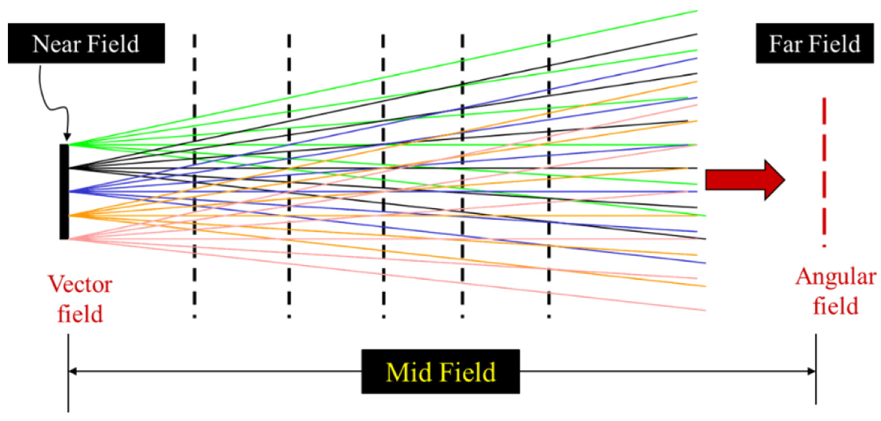
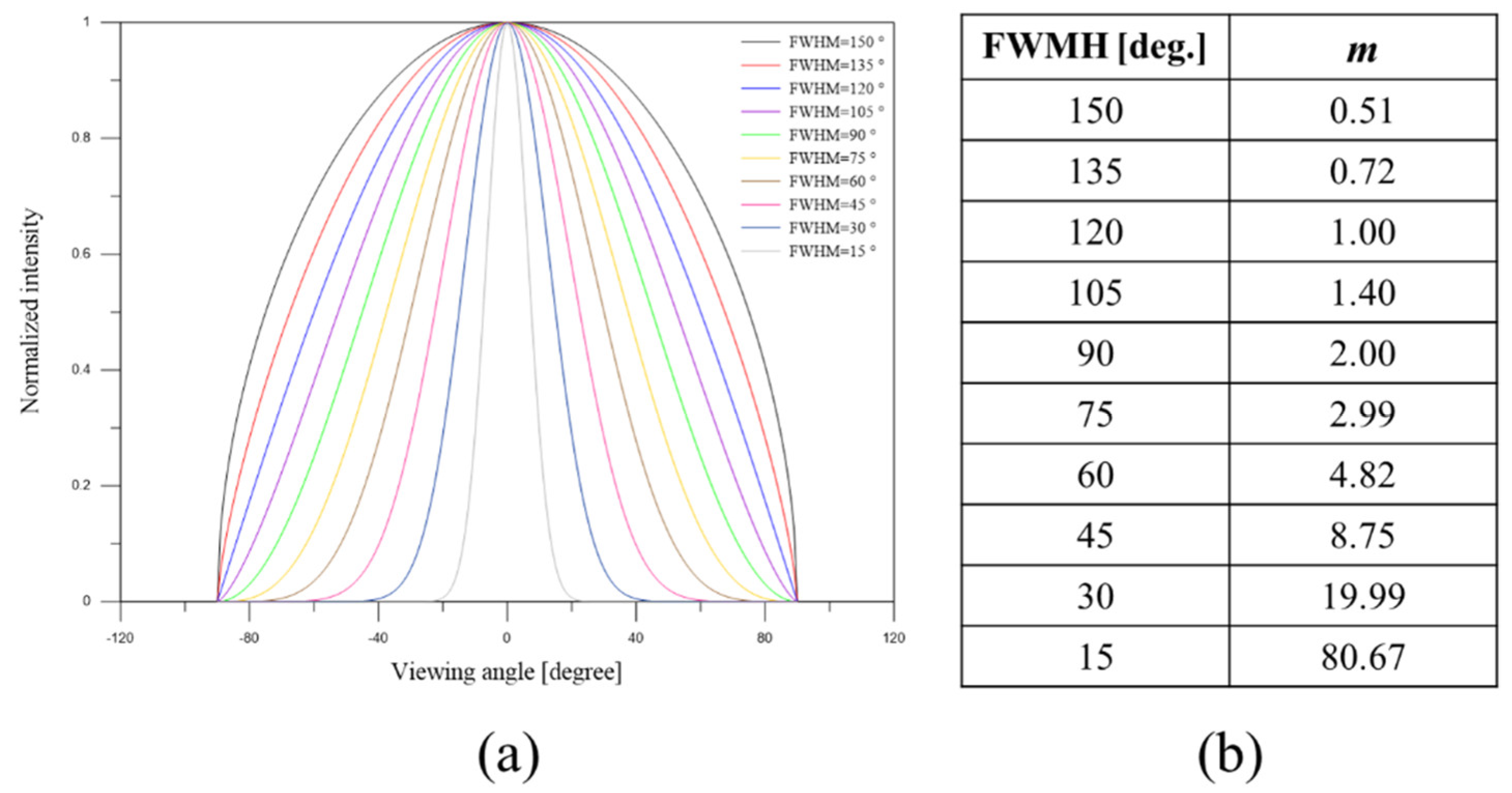
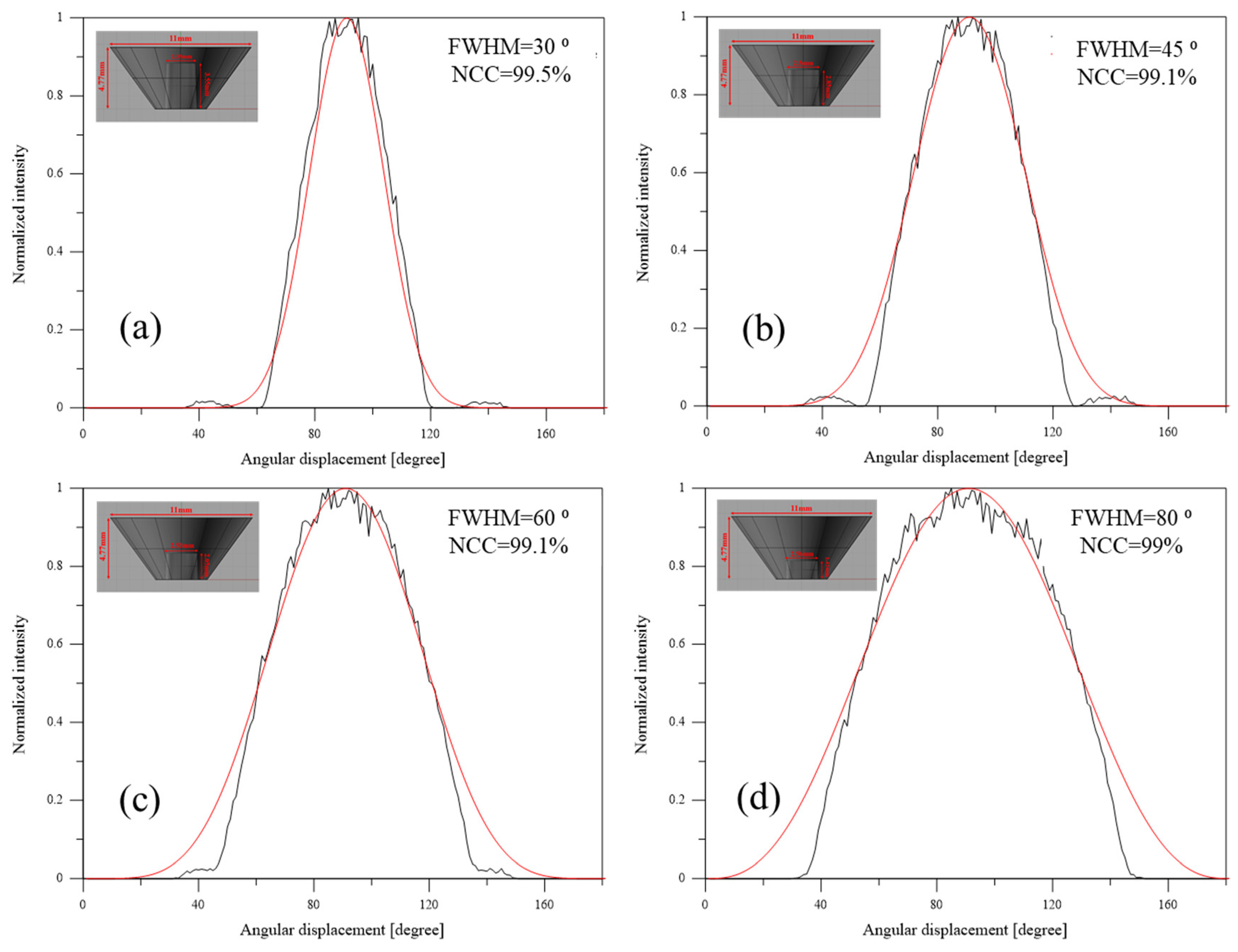
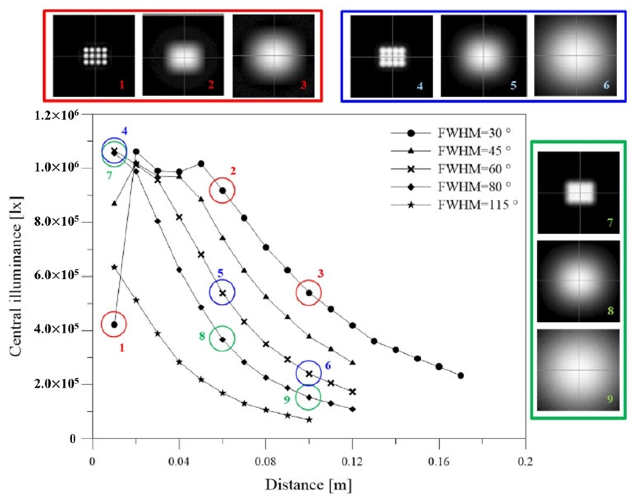
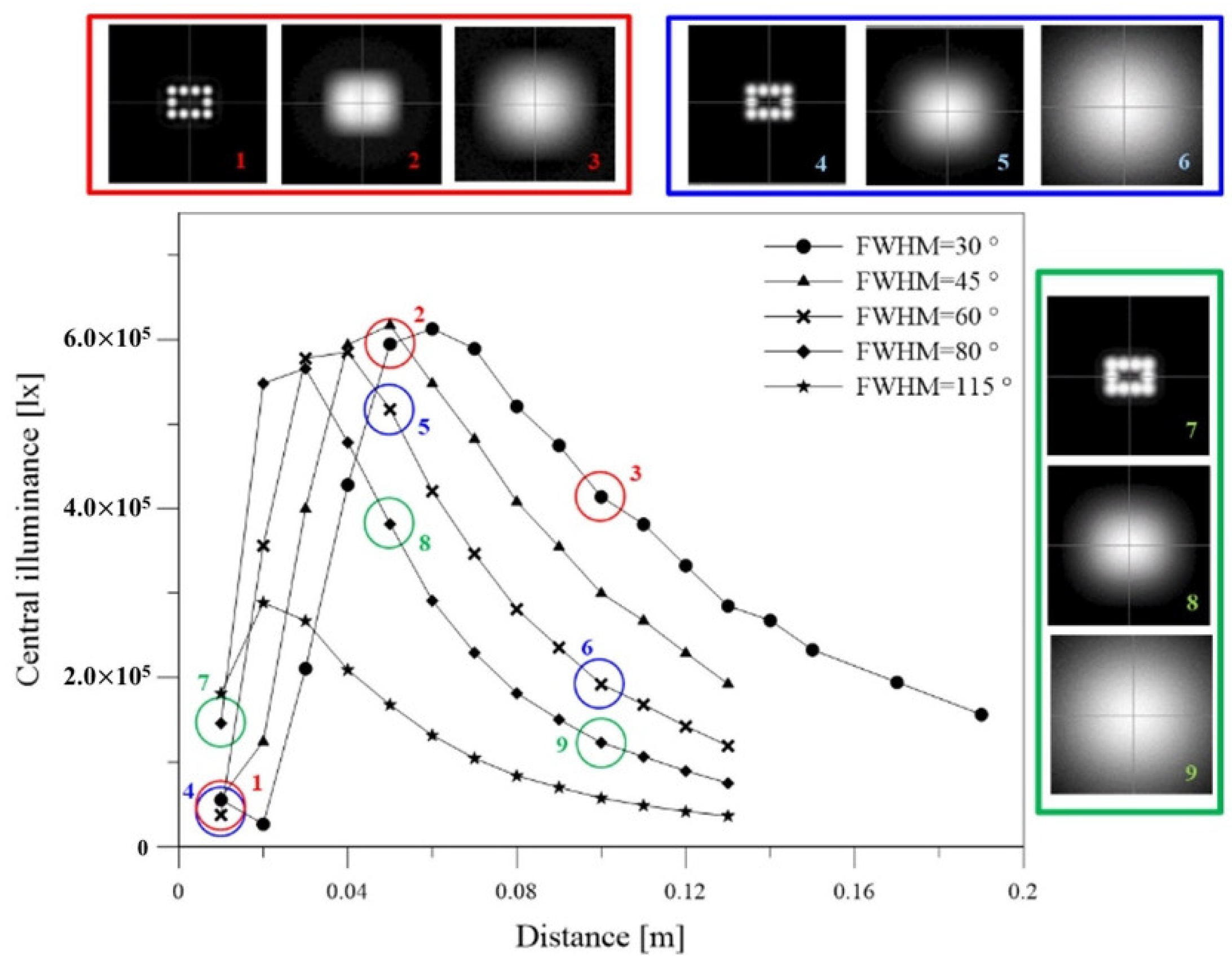
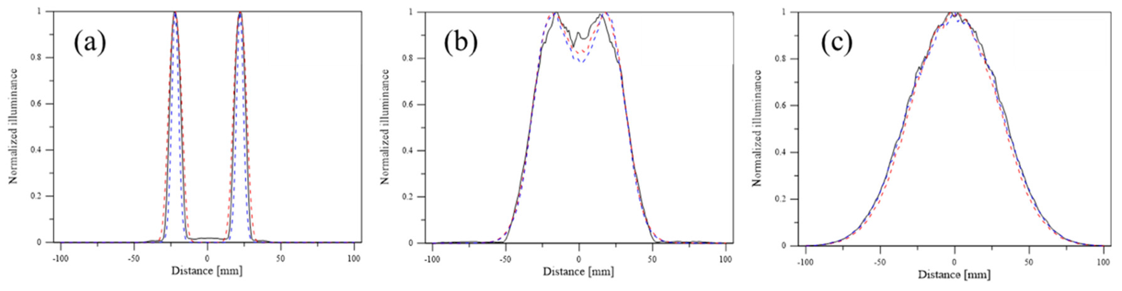
  • The LED array forms unacceptable hotspots on the illumination plane when the observation distance is not sufficiently long.
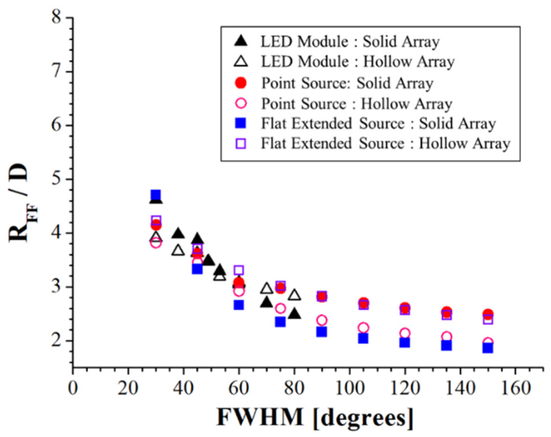
  • Hotspot removal depends on the factors including a larger divergent angle of the light source module, smaller light source array spacing, and longer observation distance.
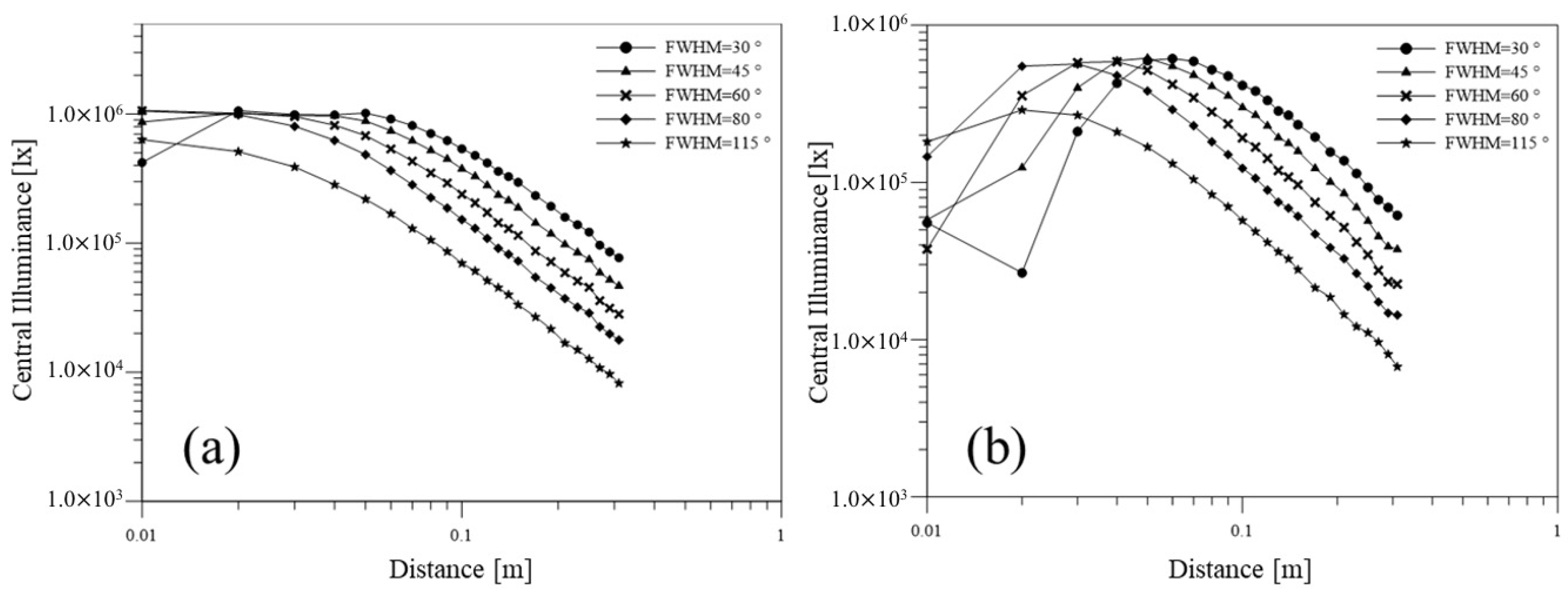
  • When the hotspot merges, central illuminance obeys the inverse-cosine law, with observation distance location being in the far-field region. A distance farther than the SDFF can be set as the working range.
  • Under the small divergent angle of the light source and hollow array of the luminaire (i.e., serve conditions), SDFF is at most five times that of the luminaire dimension.
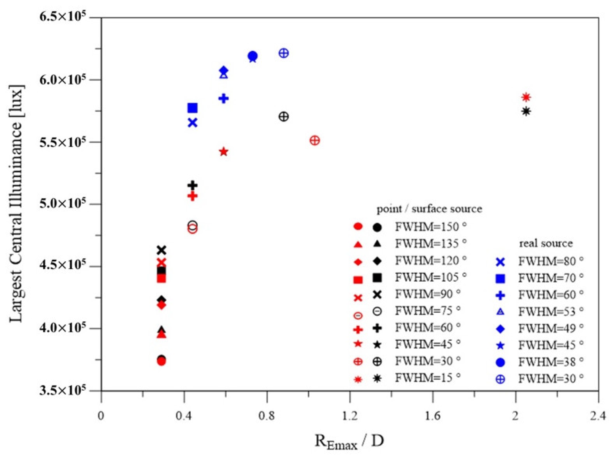
  • The LCI distance is shorter than that of the SDFF in all cases. In other words, obtaining LCI in the far field region is difficult.
  • For a specific real light source, simplified light sources such as a point source or a flat-extended source equipped with a corresponding cosine power factor of intensity can be used to determine the appropriate working range.

Author Contributions

Conceptualization and writing work, C.-C.S.; simulation, Y.-S.L.; discussion, T.-H.Y., C.-S.W., X.-H.L., Y.-S.L., S.-K.L., and Y.-W.Y.; revision, X.-H.L., C.-C.S. All authors have read and agreed to the published version of the manuscript.

Funding

This research was funded by the Ministry of Science and Technology of the Republic of China, grant numbers MOST 106-2221-E-008-065-MY3 and 108-2622-E-008-010-CC2.

Acknowledgments

The author would like to thank BRO for sponsoring ASAP, and all team members led by Ching-Cherng Sun and Tsung-Hsun Yang for supporting.

Conflicts of Interest

The authors declare no conflict of interest.

References

  1. Cree: Continues to Push the Boundaries of LED Performance. Available online: https://www.cree.com/news-media/news/article/cree-first-to-break-300-lumens-per-watt-barrier (accessed on 28 April 2020).
  2. Sun, C.C.; Chang, Y.Y.; Yang, T.H.; Chung, T.Y.; Chen, C.C.; Lee, T.X.; Li, D.R.; Lu, C.Y.; Ting, Z.Y.; Glorieux, B.; et al. Packaging efficiency in phosphor-converted white LEDs and its impact to the limit of luminous efficacy. J. Solid State Light. 2014, 1, 19. [Google Scholar] [CrossRef] [Green Version]
  3. Narendran, N.; Maliyagoda, N.; Bierman, A.; Pysar, R.; Overington, M. Characterizing white LEDs for general illumination applications. Proc. SPIE 2000, 3938, 240–248. [Google Scholar] [CrossRef]
  4. Steigerwald, D.A.; Bhat, J.C.; Collins, D.; Fletcher, R.M.; Holcomb, M.O.; Ludowise, M.J.; Martin, P.S.; Rudaz, S.L. Illumination with solid state lighting technology. IEEE J. Sel. Top. Quantum Electron. 2002, 8, 310–320. [Google Scholar] [CrossRef]
  5. Zukauskas, A.; Shur, M.S.; Caska, R. Introduction to Solid-State Lighting; John Wiley & Sons: New York, NY, USA, 2002; ISBN 978-0-471-21574-5. [Google Scholar]
  6. Schubert, E.F.; Kim, J.K. Solid-state light sources getting smart. Science 2005, 308, 1274–1278. [Google Scholar] [CrossRef] [PubMed]
  7. Schubert, E.F. Light-Emitting Diods, 2nd ed.; Cambridge University Press: New York, NY, USA, 2006; ISBN 9780521865388. [Google Scholar]
  8. Krames, M.R.; Shchekin, O.B.; Mueller-Mach, R.; Mueller, G.O.; Zhou, L.; Harbers, G.; Craford, M.G. Status and future of high-power light-emitting diodes for solid-state lighting. J. Disp. Technol. 2007, 3, 160–175. [Google Scholar] [CrossRef] [Green Version]
  9. Pimputkar, S.; Speck, J.S.; DenBaars, S.P.; Nakamura, S. Prospects for LED lighting. Nat. Photon. 2009, 3, 180–182. [Google Scholar] [CrossRef]
  10. Karlicek, B.; Sun, C.C.; Zissis, G.; Ma, R. Handbook of Advanced Lighting Technology; Springer: Cham, Switzerland, 2017; ISBN 978-3-319-00175-3. [Google Scholar]
  11. Xie, R.J.; Hirosaki, N.; Kimura, N.; Sakuma, K.; Mitomo, M. 2-phosphor-converted white light-emitting diodes using oxynitride/nitride phosphors. Appl. Phys. Lett. 2007, 90, 191101. [Google Scholar] [CrossRef]
  12. Won, Y.H.; Jang, H.S.; Cho, K.W.; Song, Y.S.; Jeon, D.Y.; Kwon, H.K. Effect of phosphor geometry on the luminous efficiency of high-power white light-emitting diodes with excellent color rendering property. Opt. Lett. 2009, 34, 1–3. [Google Scholar] [CrossRef]
  13. Kuo, T.W.; Liu, W.R.; Chen, T.M. High color rendering white light-emitting-diode illuminator using the red-emitting Eu2+-activated CaZnOS phosphors excited by blue LED. Opt. Express 2010, 18, 8187–8192. [Google Scholar] [CrossRef]
  14. Wang, S.; Wang, K.; Chen, F.; Liu, S. Design of primary optics for LED chip array in road lighting application. Opt. Express 2011, 19, 716–724. [Google Scholar] [CrossRef]
  15. Lee, X.H.; Moreno, I.; Sun, C.C. High-performance LED street lighting using microlens arrays. Opt. Express 2013, 21, 10612–10621. [Google Scholar] [CrossRef] [PubMed]
  16. Lo, Y.C.; Cai, J.Y.; Tasi, M.S.; Tasi, Z.Y.; Sun, C.C. Side-illuminating LED luminaires with accurate projection in high uniformity and high optical utilization factor for large-area field illumination. Opt. Express 2014, 22, 365–375. [Google Scholar] [CrossRef] [PubMed]
  17. Kravchenko, S.V.; Byzov, E.V.; Moiseev, M.A.; Doskolovich, L.L. Development of multiple-surface optical elements for road lighting. Opt. Express 2017, 25, 23–35. [Google Scholar] [CrossRef]
  18. Martin, G.; Marty, C.; Bornoff, R.; Poppe, A.; Onushkin, G.; Marta, R.; Yu, J. Luminaire digital design flow with multi-domain digital twins of LEDs. Energies 2019, 12, 2389. [Google Scholar] [CrossRef] [Green Version]
  19. Moreno, I.; Avendaño-Alejo, M.; Tzonchev, R.I. Designing light-emitting diode arrays for uniform near-field irradiance. Appl. Opt. 2006, 45, 2265–2272. [Google Scholar] [CrossRef]
  20. Sun, C.C.; Lee, T.X.; Ma, S.H.; Lee, Y.L.; Huang, S.M. Precise optical modeling for LED lighting verified by cross correlation in the midfield region. Opt. Lett. 2006, 31, 2193–2195. [Google Scholar] [CrossRef]
  21. Chien, W.T.; Sun, C.C.; Moreno, I. Precise optical model of multi-chip white LEDs. Opt. Express 2007, 15, 7572–7577. [Google Scholar] [CrossRef]
  22. Sun, C.C.; Chien, W.T.; Moreno, I.; Hsieh, C.C.; Lo, Y.C. Analysis of the far-field region of LEDs. Opt. Express 2009, 17, 13918–13927. [Google Scholar] [CrossRef]
  23. Moreno, I.; Sun, C.C. LED array: Where does far-field begin? Proc. SPIE 2008, 7058. [Google Scholar] [CrossRef]
  24. Moreno, I.; Sun, C.C.; Rumen, I. Far-field condition for light-emitting diode arrays. Appl. Opt. 2009, 48, 1190–1197. [Google Scholar] [CrossRef] [Green Version]
  25. Goodman, J.W. Introduction to Fourier Optics; Roberts and Company Publishers: Greenwood Village, CO, USA, 2005. [Google Scholar]
  26. Moreno, I.; Sun, C.C. Modeling the radiation pattern of LEDs. Opt. Express 2008, 16, 1808–1819. [Google Scholar] [CrossRef] [PubMed]
  27. Cree Inc. Available online: https://www.cree.com/led-components/products/xlamp-leds-discrete/xlamp-xp-e (accessed on 28 April 2020).
  28. Chang, M.B. Total internal reflection lens. Appl. Opt. 1985, 24, 1256–1259. [Google Scholar] [CrossRef] [PubMed]
  29. Breault Research Organization: Advanced Systems Analysis Program. Available online: http://www.breault.com/ (accessed on 28 April 2020).
  30. Lewis, J.P. Vision Interface 95; Canadian Image Processing and Pattern Recognition Society: Quebec, QC, Canada, 1995; p. 120. [Google Scholar]
Figure 1. Different illuminance fields for different observation distances.
Crystals 10 00360 g001
Figure 2. (a) Normalized intensity versus viewing angle for different cosine power factor; (b) Corresponding table for the cosine power factor versus full width at half maximum (FWHM).
Crystals 10 00360 g002
Figure 3. (a) XPE and (b) total internal reflection (TIR) lens structures.
Crystals 10 00360 g003
Figure 4. Designed light patterns (black line) fitted with cosine power factors (red line), for the FWHM of (a) 30 ° , (b) 45 ° , (c) 60 ° , and (d) 80 ° .
Crystals 10 00360 g004
Figure 5. (a) Solid and (b) hollow LED-array luminaires.
Crystals 10 00360 g005
Figure 6. Central illuminance (log scale) versus observation distance (log scale) for (a) the solid and (b) hollow arrays with different divergent angles of the light source modules.
Crystals 10 00360 g006
Figure 7. Central illumination location patterns in solid array. Red, FWHM: 30 ° ; blue, FWHM: 60 ° ; green, FWHM: 80 ° .
Crystals 10 00360 g007
Figure 8. Central illumination location patterns in hollow array. Red, FWHM: 30 ° ; blue, FWHM: 60 ° ; green, FWHM: 80 ° .
Crystals 10 00360 g008
Figure 9. Light patterns simulation for the light source with 30 ° divergent angle at (a) 10, (b) 50, and (c) 100 mm distances.
Crystals 10 00360 g009
Figure 10. Starting distance of the far field (SDFF)-to-luminaire ratio size versus divergent angle of the light sources.
Crystals 10 00360 g010
Figure 11. Largest central illuminance (LCI) with respect to observation distance-to- luminaire dimension ratio in hollow array (red dots: point source, black dots: flat extended source, blue dots: LED module).
Crystals 10 00360 g011

