1. Introduction
In next-generation network architectures such as Information-Centric Networking (ICN), in-network caching is one of the core functions to achieve efficient content distribution [
1,
2,
3,
4]. ICN uses location-independent names to uniquely identify each piece of content and replaces traditional security mechanisms that rely on communication channel protection with content-based security [
5], which achieves complete separation of content and its location. This enables the network layer to transparently cache content and efficiently serve subsequent requests: users can directly retrieve data from nearby nodes with cached content replicas using the content’s name, without having to access the original server. This significantly reduces network connection demands, minimizes redundant traffic and bandwidth consumption, and effectively optimizes end-to-end latency performance [
6,
7].
To achieve large-scale deployment of ICN caching, the primary challenge lies in the design and implementation of cache nodes. Since caching operations in ICN are closely coupled with the forwarding pipeline, the I/O rate of the caching system must meet strict performance requirements to match the forwarding rate of network components [
8]. For instance, high-speed memory (such as DRAM) is typically used to enable line-speed caching operations, but it has limitations in terms of cost and cache capacity. In the context of large-scale Internet traffic, the effectiveness of ICN in-network caching depends largely on the ability to provide sufficient cache capacity to host a large number of content replicas [
9], thereby improving the cache hit rate. Persistent storage devices such as SSDs (Solid-State Drives), with their lower upfront costs and higher storage capacities, can offer scalability at the terabyte (TB) level for ICN caching. However, high access latency remains a major limitation to their widespread application in ICN cache nodes.
In this context, researchers have begun exploring the use of multiple storage technologies to construct hierarchical cache architectures in order to address the trade-offs between cache capacity, deployment costs, and read/write speed [
8]. A typical approach is to use SSDs as an additional cache layer to DRAM [
9,
10,
11], where the core idea is to store a small amount of popular data in DRAM to fully utilize its high-speed memory bandwidth, while storing less popular data in SSDs to leverage their large storage capacity. At the same time, DRAM is used to store indexes and act as a write buffer for the SSD cache. In addition, related research has further optimized the access latency performance of hierarchical cache architectures by adopting techniques such as data prefetching [
12] and decoupling caching from forwarding operations [
13].
Cache management in hierarchical cache architectures remains an unresolved issue. Existing research typically handles local replica management within a single cache layer through cache replacement policies [
14]. However, in hierarchical cache architectures, the differentiated read/write characteristics of various storage media present new challenges for replica management. For example, the limited lifespan of SSDs means that they can only endure a finite number of erase/write cycles, so unnecessary write operations should be avoided to reduce the operating costs of the cache system. Most existing studies filter data written to SSDs based on attributes like content popularity [
10,
15], but they do not fully consider the characteristic information of the node and network dimensions in ICN, which leads to inefficient filtering or underutilization of SSD cache space.
In addition, the key issue in cache management lies in designing cache replacement policies that can adapt to the characteristics of the hierarchical cache architecture. Due to the differences in cache load and request access patterns between the upper and lower layers, homogeneous cache management may lead to a decline in overall cache performance. Specifically, when data are forwarded through a cache node, DRAM inserts the data into the local cache based on the cache decision results, while the input load on the SSD primarily comes from the data replaced by DRAM. As a result, the SSD experiences lower cache load and replacement frequency, allowing for more refined replica management with relatively small overhead. On the other hand, due to the filtering effect of the upper-layer cache on the workload, the request arrival patterns in the lower-layer cache tend to be different. This characteristic can be leveraged to implement differentiated cache replacement policies across multiple cache layers, adapting to their respective request access patterns, thereby improving overall cache hit rate.
To address the above issues, this paper proposes a cache management scheme oriented towards hierarchical cache architectures in ICN. In the following text, we will refer to it as the hierarchical cache management policy (denoted as HCM). The core ideas of HCM are as follows:
A differentiated cache replacement policy is proposed to accommodate the varying request access patterns across different cache layers. At the DRAM cache layer, LRU is used to prioritize retaining short-term popular data. At the SSD cache layer, a multi-queue replacement policy based on cache utility is implemented, with the goal of storing higher-utility data (such as long-term popular data or data with high retrieval costs) in SSDs for a longer period;
Considering the limited lifespan of SSDs, a probabilistic insertion-based SSD cache admission filtering mechanism is introduced. By leveraging the redundancy and popularity attributes of data in ICN, this mechanism effectively reduces the write load on the SSD while improving the overall cache hit rate.
We conducted extensive simulations based on Icarus [
16] and comprehensively evaluated the performance of HCM under various application scenarios using performance metrics such as cache hit rate, network link load, and SSD write load. The experimental results show that HCM consistently demonstrates significant cache performance advantages under different request workloads and replica placement strategies, highlighting its wide applicability across multiple application scenarios. Furthermore, HCM is able to maintain stable performance gains under different cache capacity settings, demonstrating its excellent scalability.
It should be noted that the approach proposed in this paper is not limited to ICN. It can also be applied to other distributed caching and storage scenarios, where nodes may utilize a multi-level cache hierarchy consisting of DRAM and SSD. Designing efficient cache replacement policies to improve cache resource management and system performance is equally crucial in these contexts. The ideas of SSD cache filtering and hierarchical cache replacement in HCM can be effectively applied to such environments as well. However, in this paper, we focus on the ICN context for the following reasons: First, the coupled nature of forwarding and caching in ICN presents unique challenges for cache management. For example, the limited resources of routers constrain the complexity of cache management, and features such as on-path caching impose higher demands on write throughput. On the other hand, symmetric routing in ICN, along with features like ubiquitous and transparent caching, provides greater flexibility and design space for cache management schemes. Therefore, while the HCM method has broader applicability, exploring it within the ICN context allows us to address specific challenges and optimize cache management schemes for this network architecture.
The remainder of this paper is organized as follows.
Section 2 provides an overview of the hierarchical cache architecture in ICN and related research on ICN cache replacement.
Section 3 introduces the hierarchical cache management architecture designed in this paper.
Section 4 elaborates on the hierarchical cache management policy and its core components.
Section 5 describes the experimental design and result analysis. Finally,
Section 6 summarizes the main contributions of this paper and briefly discusses future research directions.
3. Hierarchical Cache Architecture Design
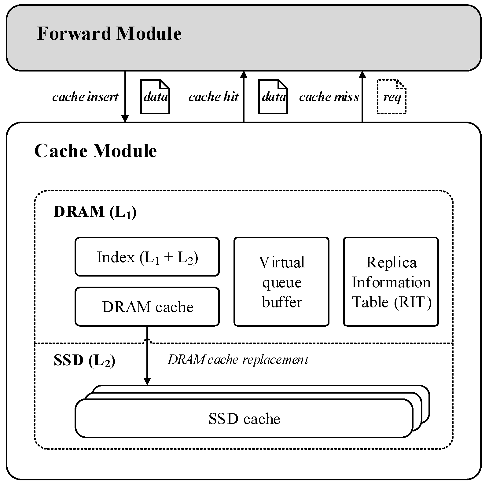
To bypass the line-speed limitations of ICN in-network caching while providing terabyte-level single-node cache capacity, we adopt a two-tier cache architecture combining DRAM and SSD. As shown in
Figure 1, we follow the design of the split architecture from [
13], dividing each ICN cache router into two functional modules: a forward module and a cache module. By decoupling packet forwarding and caching operations on the timescale, this approach addresses the issue of SSDs’ slow I/O blocking the forwarding pipeline. Specifically, the forward module is responsible for operations such as name-based routing and packet forwarding, while the cache module handles cache-related operations such as replica management and data request service. The cache module consists of two types of storage media: DRAM and SSD. The DRAM cache space is further divided into four parts. One part is used to store the indexes of replicas in the L1 and L2 cache layers, another part is used to store the DRAM virtual cache queue, a third part is used to store the Replica Information Table (RIT), and the remaining space is used to store the actual replica data. The first three parts occupy only a small amount of space, and their specific implementation will be introduced in
Section 4. The SSD is deployed in a scalable manner, allowing network administrators to adjust the number of SSDs based on cache capacity requirements. The SSD cache space primarily holds the replicas evicted from the DRAM cache to ensure the exclusivity of the hierarchical cache system [
44], meaning that the same replica is not cached in multiple layers.
The proposed architecture involves three core operations: cache insertion, cache hit, and cache miss, as indicated by the arrows in
Figure 1. Specifically, when a new data packet is forwarded to the node, the cache module is responsible for establishing an index and storing the corresponding replica data. When a new request packet is forwarded to the node, it queries the index table in DRAM. If the request hits any cache level, the corresponding replica data are read from the cache device indicated by the index, and the forward module encapsulates it into an ICN data packet to be returned to the requesting node, while updating the corresponding entry in the RIT. If the request misses at any cache level, the forward module forwards the packet to other cache nodes or original servers based on the name-based routing protocol.
4. Hierarchical Cache Management (HCM) Policy
The key to hierarchical cache management lies in how to allocate cache levels for replicas based on the read and write characteristics of different storage media, ensuring the efficient utilization of cache resources at each level. At the same time, it is necessary to design tailored replica replacement policies for each cache layer based on its differentiated workload characteristics, in order to improve the hit rate of the caching system.
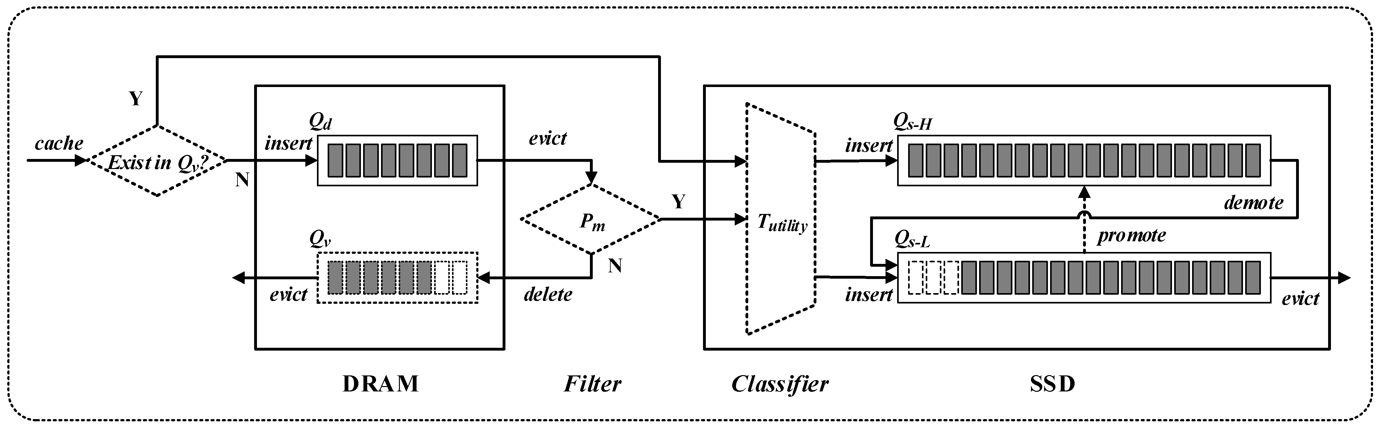
The hierarchical cache management (HCM) policy designed in this paper is shown in
Figure 2. DRAM serves as the upper-level cache, responsible for caching new replicas, aiming to fully utilize DRAM’s high memory bandwidth to improve the overall I/O throughput of the cache system. A cascading connection is used between the upper-level DRAM cache and the lower-level SSD cache, meaning the write load to the SSD cache mainly originates from the replica replacements in the DRAM cache, ensuring the exclusivity of the layered cache and efficient use of cache resources. To further reduce the write load on the SSD cache, a cache admission filter is placed in front of the SSD cache. This filter uses information such as replica popularity and redundancy to filter the write load, thereby reducing the write/erase cycle frequency and wear-related operational costs of SSDs.
Considering the filtering effect of the upper-level cache on request loads, differentiated replica replacement policies are adopted between each cache layer to accommodate their respective request arrival patterns. Specifically, considering the temporal locality [
45] characteristics of the request sequence, each cache level adopts LRU as the base management policy to improve the hit rate of short-term popular data. For the heavy-tailed distribution of data popularity [
46], an SSD filter is introduced to further filter out long-term popular data replicas. In addition, to address the diverse optimization objectives of cache management, the SSD cache employs a multi-queue replica management scheme based on cache utility, optimizing the overall cache performance. In the following sections, we will provide a detailed description of the three key components of HCM: DRAM cache replica management, SSD cache admission filtering, and SSD cache replica management.
4.1. DRAM Cache Replica Management
The replicas in the DRAM cache are managed by an LRU queue (denoted as ), with LRU serving to capture the temporal locality of requests. However, DRAM can only provide cache capacity in the range of tens of gigabytes. In heavy traffic scenarios, cache replacement in occurs very frequently, leading to short residency times for replicas in the cache, making it difficult for them to be hit by subsequent requests. To address this, we allocate a portion of DRAM space for a virtual cache queue (denoted as ), which uses an LRU queue to track the replicas recently replaced in . The purpose of is to observe the request access patterns of replicas over a longer time scale. The term “virtual” indicates that the replica data in are not actually stored in DRAM; it is only used to maintain the historical cache replacement records of DRAM.
The Replica Information Table (RIT) in
Figure 1 is used to record the attribute information corresponding to each locally cached replica, including but not limited to the replica’s popularity, redundancy, and cache distance. Specifically, the popularity value can be set as the number of request hits for the replica at the current node, the redundancy value can be set as the number of replicas cached upstream of the node, and the cache distance is used to record information such as the number of hops or the delay between the current node and upstream service nodes. When a data request hits any node, the corresponding content attributes of the replica are retrieved from its local RIT and added to the header fields of the returned data packet. Along the content delivery path, intermediate nodes can read and update these header fields, such as incrementing the cache distance field hop-by-hop or increasing the redundancy field value by 1 after the data are cached locally.
When a new replica is inserted into
, it is directly placed at the tail of
according to the LRU rule, and its corresponding popularity and redundancy information is recorded in the local RIT, as described earlier. When a new request hits a replica in
, the replica is first moved to the tail of
, and its local popularity information is updated accordingly. When a replacement occurs in
, the replaced replica is further processed by the SSD cache admission filter described in
Section 4.2. Specifically, replicas that pass through the filter are written to the SSD cache, while those that do not pass the filter are removed from DRAM, and the corresponding entry is inserted into the virtual cache queue
.
4.2. SSD Cache Admission Filter
SSDs have a limited lifespan, which necessitates minimizing their write/erase cycle frequency to reduce wear-related operational costs. To decrease the write load on SSDs while ensuring that cache hit rates in the network remain optimal, careful selection of replicas to be inserted into the SSD cache is required. To achieve this, we leverage statistical information on replica popularity and consider the cache redundancy characteristics in ICN. We have designed a cache admission filter based on probabilistic insertion, which effectively reduces both SSD write operations and cache replacement rates. At the same time, by filtering out content with low cache utility, the overall cache hit rate is improved.
In our design, the write load on the SSD cache consists of two main components. One part of the load comes from cache hits in the DRAM virtual queue (). Specifically, when a request hits , it indicates that the corresponding replica has a short request interval, which typically suggests that the replica has high popularity or strong temporal locality. As a result, when the data for this replica are returned, we directly insert them into the SSD cache. The other part of the load comes from the cache replacement process in the DRAM cache queue (). The SSD cache admission filter checks these replicas and, based on the filtering results, probabilistically inserts them into the SSD cache. The following sections will provide a detailed description of the three main processes of the SSD cache filter: popular replica selection, redundant replica filtering, and cache load tuning.
4.2.1. Popular Replica Selection
To increase the probability of cache hits for subsequent requests, replicas of content with higher popularity should be prioritized for caching [
47]. This is a fundamental consensus in cache management strategy design. During the popular replica selection process, the filter maintains a popularity threshold (denoted as
) to indicate the minimum request count that a replica must meet before being written to the SSD. Its purpose is to filter out content that is requested only once [
48]. For replicas replaced in the DRAM cache queue (
), the result of the popularity filtering is represented by a 0–1-valued Boolean variable
, as shown in Equation (1), where
denotes the popularity of replica
at the current node. Specifically, when
is 1, it indicates that the replica passes the popularity filter, and the subsequent filtering process can continue. When
is 0, it means the replica fails the popularity filter, and no further processing will be carried out.
4.2.2. Redundant Replica Filtering
The distributed nature of ICN in-network caching inevitably leads to cache redundancy issues among cache nodes. Under limited cache capacity, higher redundancy means lower diversity of cached replicas, which limits the improvement of cache hit rates. To address this, we leverage implicit cooperation among on-path nodes during data transmission, enabling each node with a certain degree of replica redundancy perception ability. As described in
Section 4.1, the RIT records redundancy information for each local cached replica, which indicates the number of replicas cached by upstream nodes at the time the replica is cached in the current node. It is important to note that although the cache status of upstream nodes is dynamic, it still provides an effective estimate of replica redundancy. Specifically, for a replica
that has passed the popularity filtering, let its redundancy value be
. The redundancy filtering result for this replica can be represented by the cache admission probability
as shown in Equation (2).
4.2.3. Cache Load Tuning
The data transfer speeds of SSD and DRAM differ significantly, and the write load on the SSD must be carefully controlled to avoid data loss. Although the number of replicas written to the SSD has been greatly reduced through the filtering process described above, there may still be some cache redundancy between nodes on different transmission paths, which could lead to decreased cache utilization efficiency. To address this, we introduce a load tuning function, , based on the cache admission probability described above, with a value range of . The purpose of is to further adjust the SSD replica admission probability to ensure that the SSD write load does not exceed its I/O bandwidth. Specifically, can be dynamically adjusted based on the write load at time or set to a fixed value (e.g., 0.1).
Based on the above, for any replica
replaced in the DRAM cache queue (
), its SSD admission probability
can be expressed by Equation (3), where
is given by Equation (2).
Algorithm 1 summarizes the entire process of SSD cache filtering described above.
| Algorithm 1: SSD Cache Filtering |
1: if DRAM cache replacement occurs then
2: ← Get replaced replica based on LRU
3: end if
4:
5: if SSD cache space not full then
6: ← Get cache load tuning value
7:
8: else
9: ← Get replica popularity from local RIT
10: then
11: ← Get replica redundancy from local RIT
12:
13: ← Get cache load tuning value
14:
15: else
16:
17: end if
18: endif
19: Generate a random decimal between (0,1)
20: then
21: ← True
22: end if |
4.3. SSD Cache Replica Management
The write frequency of replicas in SSDs is much lower than that in DRAM, which allows for more refined replica management with relatively low overhead. To achieve this, we have designed a multi-queue cache replacement policy based on cache utility, where the cache utility can be customized by network administrators according to different cache optimization objectives. The multi-queue design allows replicas with different utility values to be provided with different levels of cache replacement frequency, thereby improving the overall cache performance. Specifically, replicas cached in the SSD are managed using two LRU queues, denoted as and . is used to maintain replicas with high cache utility values, while is used to maintain those with low cache utility values. The two LRU queues are linked end-to-end, so that replicas replaced in can be directly demoted to for continued caching, thereby extending the residency time of high-utility replicas in the cache. Replicas replaced in are simply removed from the SSD cache.
Before a new replica is written to the SSD cache, a classifier determines the target queue for insertion. Specifically, the classifier is responsible for maintaining a cache utility threshold (denoted as ) and dynamically updating this threshold during the cache management process. For each replica to be written to the SSD cache, its corresponding utility value is calculated using a predefined cache utility function. Based on whether its utility value exceeds , the replica is inserted into the corresponding LRU queue. Each new replica insertion triggers an update to to ensure it always reflects the real-time status of the SSD cache. The cache utility function can be customized according to different cache optimization goals, such as the replica’s popularity, hop count, network traffic cost, etc. It should be noted that the utility threshold should be adjusted based on the utility function, ensuring that the number of replicas written to each queue aligns with the design objectives. Algorithm 2 provides a simple implementation, where the threshold is set as the mean of the maximum and minimum utility. This results in significantly fewer replicas being written to compared to . As a result, experiences a lower replacement rate, which allows high-utility replicas to stay in the cache for a longer period.
When a new request hits the SSD cache, the corresponding replica is first moved to the tail of the LRU queue it resides in, and its cache utility value is updated. If the replica is in
, it is further checked whether its updated utility value exceeds
. If so, the replica is promoted to
. Similarly, the update of each replica’s utility value also triggers an update to
. An example of the update rule for
is presented in Algorithm 2, while Algorithm 3 summarizes the SSD cache replica management algorithm described above.
| Algorithm 2: Update_utility_threshold () |
Input: New/updated replica cache utility:
1: has never been set then
2:
3:
4:
5: else
6:
7:
8:
9: endif
10: |
| Algorithm 3: SSD Cache Management |
1: # cache insert process
2: is not full then
3:
4: else
5: ← Get cache utility of replica
6: then
7: Add
8: else
9: Add
10: endif
11: endif
12: Update_utility_threshold
13:
14: # cache hit process
15: if SSD cache hit occurs then
16: ← Get hit replica
17: end if
18: ← Update cache utility of replica
19: if then
20: Move
21: else
22: then
23: Move
24: else
25: Move
26: endif
27: endif
28: Update_utility_threshold |
5. Simulation Results and Analysis
5.1. Simulation Environment Setup
To evaluate the performance of the HCM policy, we conducted extensive comparative experiments using the Icarus simulator [
16]. Based on the Icarus v0.8.0 source code, we implemented all the functions of HCM. Additionally, for the hierarchical cache architecture scenario, we made corresponding modifications to the original LRU and LFU. Furthermore, we selected two comparison schemes, uCache [
15] and Probationary Insertion (denoted as PI) [
10], and implemented their relevant functionalities in Icarus. A brief introduction to them is provided below. The Icarus parameters used in the experiments are shown in
Table 1.
PI (Probationary Insertion): the DRAM and SSD caches are managed using two separate LRU queues. For the content evicted from the DRAM cache, if it has been accessed at least once during its time in DRAM, it is written to the SSD cache;
uCache: it uses a two-level LRU queue to manage the DRAM cache. Content that hits in the first-level LRU queue is directly promoted to the second-level LRU queue, while content evicted from the second-level LRU queue is directly written to the SSD cache. The SSD cache is managed using a single LRU queue. Additionally, the design includes a ghost buffer, which inserts content that was previously accessed but is now deleted directly into the second-level queue, allowing for the observation of data access patterns over a longer time period.
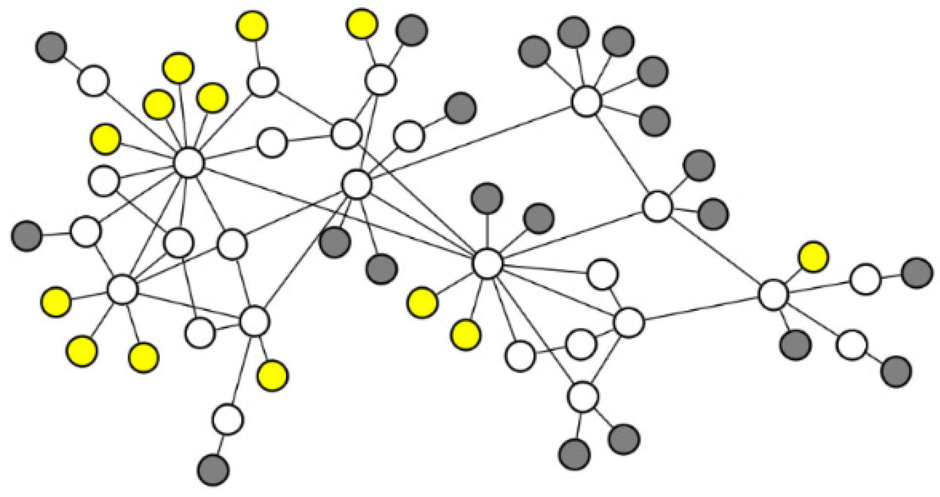
We selected the GARR topology [
49] as the network topology for the simulation, which consists of 21 receiver nodes, 27 cache nodes, and 13 server nodes. To visualize the topology, we used Gephi [
50], as shown in
Figure 3, where white nodes represent cache nodes, gray nodes represent receiver nodes, and yellow nodes represent server nodes. In addition, the bandwidth capacity of all links is set to 1 Gbps. The cache capacity is uniformly distributed across all cache nodes, with a DRAM-to-SSD capacity ratio of 1:10 for each cache node. All content is randomly assigned to a server node as its origin repository, and the size of each content item is set to 2 MB.
Additionally, HCM requires the manual configuration of certain parameters, namely the filter’s popularity threshold and the cache load tuning function . In our experiments, we tested various values and found that setting to 2 achieves optimal cache performance in most cases. This is because it effectively filters out a large portion of one-time requests. However, further increasing reduces the write load on the SSD but negatively impacts the cache hit rate. Therefore, is fixed at 2 in the subsequent experiments. As for , we simplified its configuration by setting it to a constant value of 0.1. Experimental results demonstrate that this value not only keeps the SSD write load at a very low level but also ensures good cache performance.
5.2. Simulation Results Analysis
In this section, we design three sets of experiments to evaluate the performance of HCM. Experiment 1 tests the applicability of different policies under different input traffic loads. Experiment 2 tests the performance of various replacement policies integrated with different cache placement strategies. Experiment 3 compares the scalability of different replacement policies by adjusting cache capacity. Each experiment is repeated 5 times, and the average is taken as the final result. A 95% confidence interval is also calculated for each metric to assess the statistical significance of the results. In each subsection, we will introduce the specific settings of each experiment. Below are the three cache performance evaluation metrics used in this section.
- (1)
Cache Hit Rate
Cache hit rate is one of the key metrics for measuring the performance of a caching system. It represents the proportion of requests serviced by the cache system out of the total number of requests. A higher cache hit rate means that more requests can be served directly from the cache, eliminating the need to access the original server. This not only shortens data response distances but also reduces network latency and bandwidth consumption. By improving the cache hit rate, cache resources can be utilized more efficiently, which in turn enhances overall system performance and optimizes the user experience;
- (2)
Network Link Load
Network link load refers to the amount of data transmitted over each link per unit of time. It is a key metric for evaluating the caching system’s effectiveness in reducing network traffic costs. Typically, network link load is closely related to the cache hit rate—that is, the higher the cache hit rate, the lower the link load tends to be. This is because the cache system can more effectively utilize cached data, reducing the need to fetch data directly from the original server, thus lowering network bandwidth consumption and improving network scalability. In calculating the link load, we sum the loads of all used links and take the average as the final result, providing a comprehensive assessment of the caching system’s efficiency in utilizing network resources;
- (3)
SSD Write Load
SSD write load is represented by the total number of replicas written to the SSD cache. A reasonable SSD write load is crucial for extending the lifespan of the storage device. Cache replacement policies need to improve cache hit rates while minimizing unnecessary write operations, in order to maintain the health and long-term performance of the storage device. In calculating the SSD write load, we record the total number of replicas written to the SSD cache across all nodes during the simulation process.
5.2.1. Results Analysis Across Different Traffic Groups
To simulate scenarios with mixed traffic types in real-world networks, we use the traffic generator Globetraff [
51], which generates mixed traffic workload including applications such as Web, P2P, and Video, based on specified traffic ratios and models. To validate the applicability of HCM to different traffic loads, we use Globetraff to generate four sets of traffic workloads with different mix ratios (as shown in
Table 2), with the model parameters for each traffic type listed in
Table 3. Data objects in ICN networks are typically divided into fixed-size data chunks [
3,
4]. However, there is currently no strict standardization for the size of ICN data chunks, leading to significant variations in the chunk sizes published by different content providers. To simplify the experiments and analysis, we set the size of data objects for all traffic types in the experiment to 2 MB. In addition, all other unspecified parameters are consistent with the settings in reference [
51].
In this experiment, we tested the cache performance of different replacement policies under each traffic group shown in
Table 2. To control variables, LCE (Leave Copy Everywhere) [
48] was used as the default cache placement strategy, which caches a copy of the content at each hop node along the content delivery path. The cache capacity was set to 5% of the total number of contents. The experimental results are shown in
Figure 4.
Figure 4a shows that under different input traffic loads, HCM consistently achieves the highest cache hit rate. In contrast, classical replacement policies such as LRU and LFU exhibit significant performance differences across different traffic loads, indicating that they are only suitable for specific application scenarios. For example, in traffic group A, where the proportion of Web traffic is low and the request temporal locality is weak, LRU performs poorly. However, in traffic group D, as the proportion of Web traffic increases, LRU’s performance improves significantly. Conversely, LFU shows an entirely opposite trend in performance across these two traffic groups. The PI policy, which only inserts replicas that hit in the DRAM cache into the SSD, struggles to effectively handle scenarios with longer request intervals in Video and other traffic types, resulting in a lower hit rate. In contrast, both uCache and HCM more effectively monitor changes in replica popularity by introducing virtual queues to record the most recently evicted replicas from the DRAM cache. HCM outperforms uCache in several aspects. First, HCM facilitates more accurate SSD cache admission filtering by transmitting content popularity information between nodes, ensuring that popular replicas are identified more accurately. Second, HCM introduces a redundancy estimation mechanism, further improving the hit rate. These improvements enable HCM to demonstrate outstanding cache performance across all traffic loads.
Figure 4b presents the experimental results for the network link load, which shows a significant negative correlation with the cache hit rate: the higher the cache hit rate, the lower the network link load. This is because a higher cache hit rate allows more data requests to be served directly by cache nodes that are closer, greatly reducing the amount of data transmitted through the network links. In addition, shorter response distances not only reduce bandwidth consumption but also decrease response latency, which is particularly important for latency-sensitive applications. Due to its advantage in cache hit rate, HCM consistently achieves the lowest link load across all traffic loads, significantly optimizing bandwidth utilization and improving overall network performance.
Figure 4c clearly demonstrates the important role of SSD cache admission filtering in reducing SSD write load. Since the LRU and LFU policies directly write replicas to the SSD cache without any filtering, this leads to a very high SSD write load, which not only accelerates the SSD wear and significantly shortens its lifespan but also increases the processing overhead on the cache nodes. In contrast, the PI, uCache, and HCM policies significantly reduce the SSD write load by introducing filtering mechanisms. Specifically, the PI policy has the lowest write load but may lead to the issue of underutilized SSD resources. The write load of HCM is slightly higher than that of uCache, primarily because uCache determines replica popularity based solely on local statistics, while HCM more accurately identifies popular replicas by utilizing feedback from the service nodes, resulting in better caching performance. Nevertheless, HCM’s write load remains at a relatively low level, balancing efficient SSD usage with improved cache performance.
5.2.2. Results Analysis Based on Real-World Traces
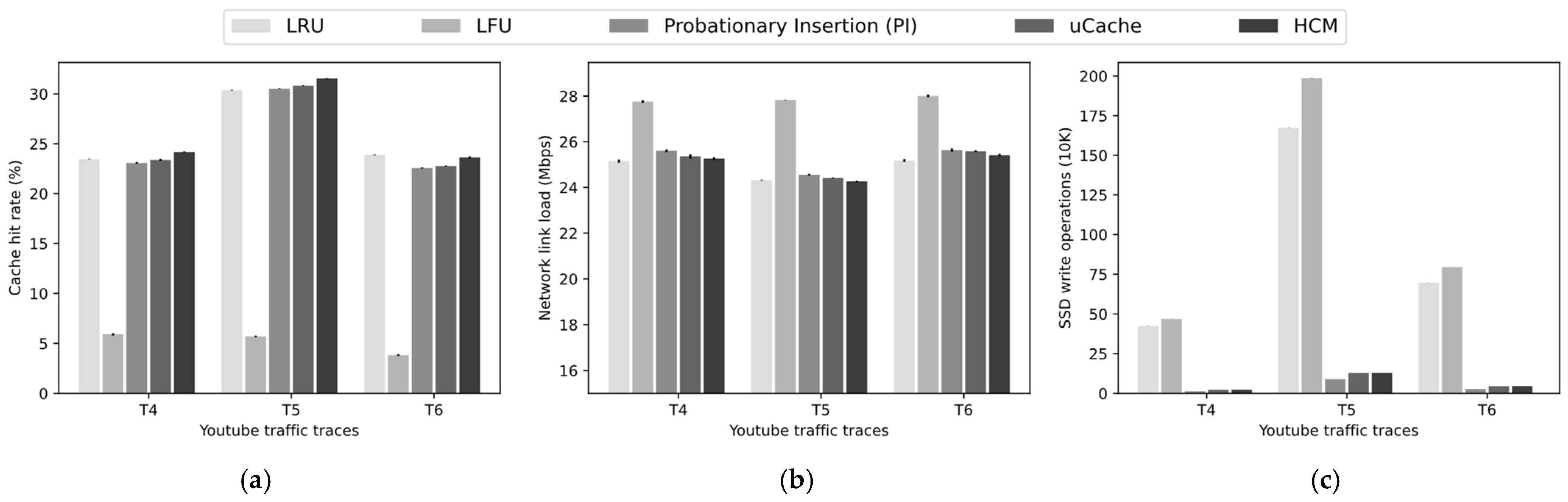
To further verify the effectiveness of HCM in real network scenarios, we use the real YouTube traffic load collected by [
53], which includes a set of traces collected on different dates, corresponding to different monitoring durations, and different numbers of requests and video clips. We selected three sets of traces, and their main parameters are shown in
Table 4. Similar to the settings in
Section 5.2.1, we use LCE as the default cache placement strategy and set the cache capacity to 5% of the total content. Additionally, to simplify the analysis, we set the size of all video clips to a uniform 2 MB. The experimental results are shown in
Figure 5.
As shown in
Figure 5a, LFU exhibits the lowest cache hit rate across different traces. This is because, compared to the synthetic traces from GlobeTraff, the real YouTube trace has a less skewed distribution of popularity, reducing LFU’s effectiveness. Additionally, the traces in this experiment were collected over a concentrated period, resulting in strong temporal locality in the request sequence, which explains why LRU achieves a higher hit rate. Since HCM uses LRU as its base management queue, its hit rate is similarly satisfactory and slightly outperforms PI and uCache. This result is consistent with the findings from the experiment using synthetic traces generated by GlobeTraff (see traffic group D in
Figure 4a): when traces exhibit strong temporal locality, LRU’s advantage is amplified, while LFU’s performance declines. The advantage of HCM lies in its ability to maintain stable performance across different traffic loads.
Figure 5b shows the network link load, which is basically inversely correlated with the cache hit rate.
Figure 5c illustrates the SSD write load. Although HCM does not significantly outperform LRU in terms of cache performance, it achieves the same results with fewer SSD write operations.
5.2.3. Results Analysis Under Different Cache Placement Strategies
The replica placement strategy controls both the location and quantity distribution of replicas, while the replica replacement policy is responsible for managing the local cached replicas. Together, they determine the overall distribution of cached replicas within the network. A good replacement policy should maintain stable performance across different placement strategies. To this end, we selected several typical replica placement strategies, including LCE, LCD (Leave Copy Down) [
48], CL4M (Cache Less for More) [
54], Random [
16], and ProbCache [
55], and studied their cache performance when combined with different replacement policies. In this experiment, we used traffic group B from
Table 2 and set the cache capacity to 5% of the total number of contents. The following is an introduction to these cache placement strategies.
LCE: a copy of the content is cached at every hop node along the content delivery path;
LCD: content is cached only at the downstream one-hop node of the current service node;
CL4M: among all the nodes along the content delivery path, the node with the highest betweenness centrality is selected to cache the content;
Random: a node along the content delivery path is randomly selected to cache the content;
ProbCache: content is cached probabilistically at each node along the content delivery path. The caching probability at each node is determined based on two key parameters: (which approximates the caching capability of the path based on traffic load) and (which reflects the router’s distance from the user). These factors guide the content caching decision to optimize cache resource utilization and reduce redundancy.
As shown in
Figure 6a, there are significant differences in cache hit rates for different replacement policies under various placement strategies. For example, under the LCE strategy, LFU outperforms LRU, while under the LCD and CL4M strategies, LFU’s performance significantly declines, and LRU performs the best. Nevertheless, HCM achieves satisfactory results under all placement strategies, indicating that it can operate stably across different placement strategies. Notably, HCM combined with Random achieves the best cache hit rate across all combinations, suggesting that good cache performance can be obtained even with simple placement decisions. This reduces the complexity of caching decisions and helps optimize the forwarding performance of ICN routers.
Figure 6b shows that HCM consistently achieves the lowest network link load across different scenarios, indicating that HCM can effectively reduce network traffic costs through closer cache hit distances. Notably, under the LCD and CL4M strategies, although HCM’s hit rate is slightly lower than LRU’s, it still results in lower network link load. This suggests that HCM, through SSD cache filtering and effective SSD cache management, can prioritize retaining replicas with higher cache utility, further reducing link load.
Figure 6c presents the experimental results for SSD write load. Since LRU and LFU lack SSD write filtering, their write load is mainly determined by the placement strategy, resulting in similar write load levels for LCD, CL4M, and Random. In contrast, HCM, uCache, and PI maintain very low write loads across different placement strategies.
5.2.4. Results Analysis Under Different Cache Capacities
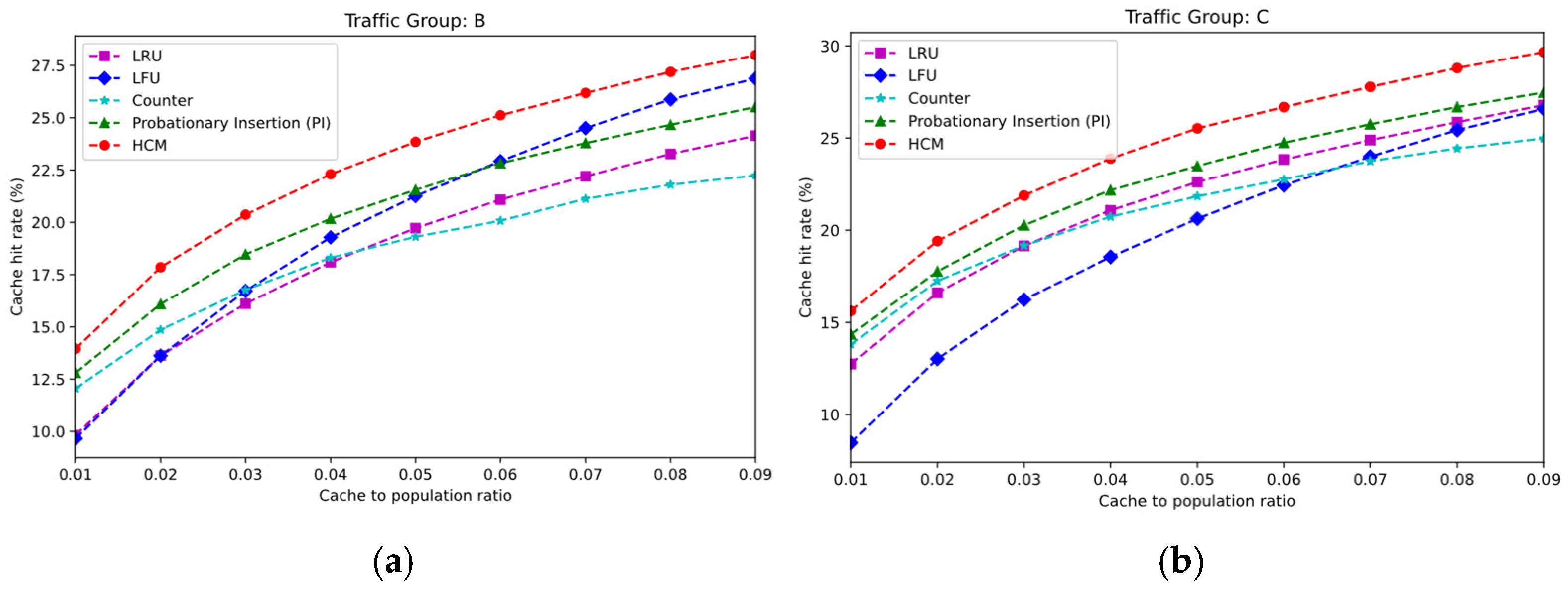
As the number of cache nodes increases or storage capacity expands, the cache capacity will increase accordingly. Therefore, the cache management policy should have good scalability to ensure that, as cache capacity grows, both the number of cached replicas and the cache hit rate can gradually improve. In this section, we evaluate the performance of different replacement policies under various cache capacity settings. The
x-axis in the figures represents the proportion of cache capacity relative to the total number of contents. Considering that the trends observed under different traffic loads and cache placement strategies are roughly the same, we selected traffic groups B and C from
Table 2 as input workloads and set the cache placement strategy to LCE.
As shown in
Figure 7, with the increase in cache capacity, the cache hit rate of all replacement policies improves, primarily due to the increased diversity of replicas in the cache. Under both traffic loads, HCM consistently achieves the highest hit rate across different cache capacities, demonstrating its broad applicability and excellent scalability in various application scenarios. In contrast, LFU shows significant differences in performance under different traffic loads. Under traffic group C, LFU’s cache hit rate is notably lower than that of other strategies, mainly because this group has a higher proportion of Web traffic, which leads to strong temporal locality between requests. However, LFU demonstrates a higher growth rate as cache capacity increases. This is because, with more cache capacity, LFU can retain more popular replicas, and in scenarios where popularity follows a heavy-tailed distribution, it can hit more requests.
As shown in
Figure 8, with the increase in cache capacity, the link load of all replacement policies decreases, and overall, there is a negative correlation with the cache hit rate. Under both traffic loads, HCM consistently achieves the lowest link load. Although LFU’s cache hit rate grows faster as cache capacity increases (as shown in
Figure 7), HCM still maintains a significant advantage in terms of link load. In addition, compared to uCache, HCM’s link load decreases more rapidly as cache capacity increases, thanks to its faster cache hit rate growth. The multi-queue replica management mechanism in HCM allows for more efficient utilization of the expanded cache space, while uCache uses a single LRU queue to manage the SSD cache, leading to limitations in SSD space utilization.
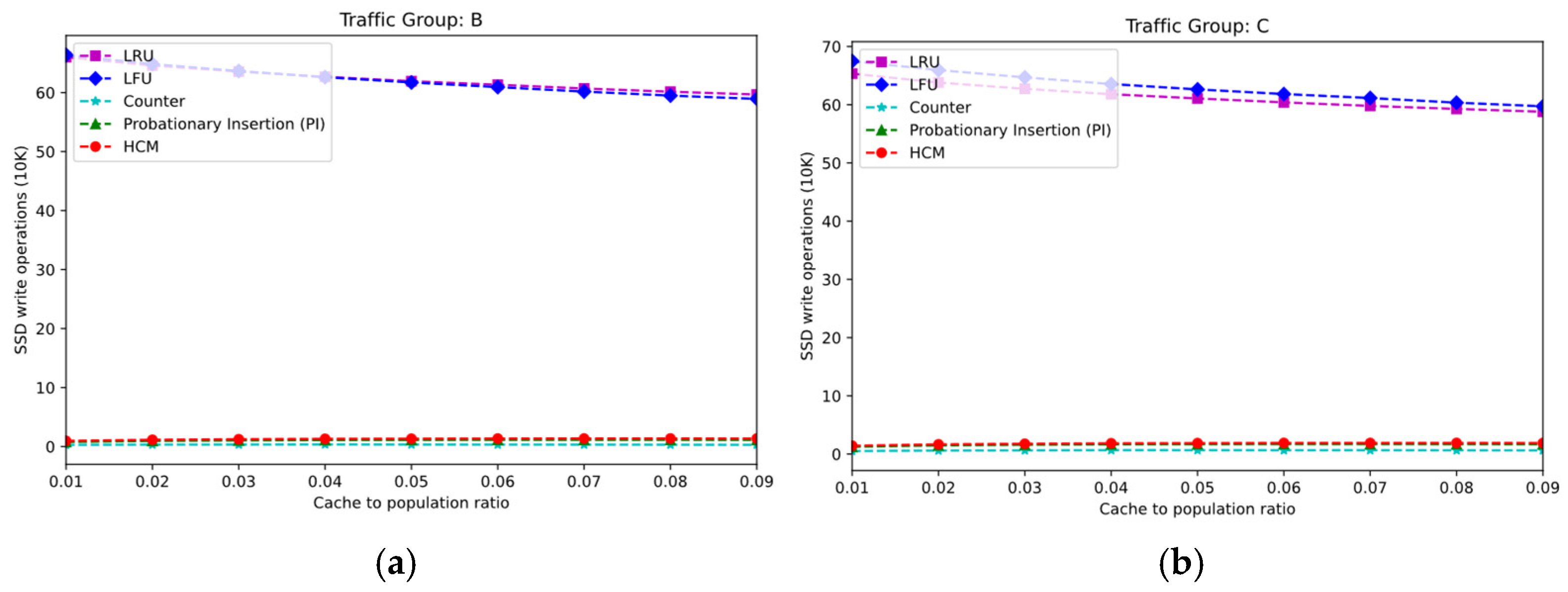
Figure 9 shows the changes in SSD write load as cache capacity increases. With the increase in cache capacity, the SSD write load of different replacement policies slightly decreases, mainly due to the improvement in the cache hit rate and the shortening of the request response distance, which alleviates the overall cache load. However, the primary factor determining the SSD write load remains the SSD admission filtering mechanism. As a result, the SSD write load of LFU and LRU remains consistently high. In contrast, HCM, uCache, and PI effectively filter the replaced replicas in DRAM based on replica popularity information, maintaining a consistently low SSD write load. In addition, HCM includes a cache load tuning option that allows the SSD admission rate to be adjusted based on demand, further reducing the SSD write load.


