Article

Integrating ISA and Part-of Domain Knowledge into Process Model Discovery

Department of Science, Technology and Innovation, Università del Piemonte Orientale, Viale Teresa Michel 11, 15121 Alessandria, Italy
*
Author to whom correspondence should be addressed.
Future Internet 2022, 14(12), 357; https://doi.org/10.3390/fi14120357
Submission received: 25 October 2022 / Revised: 19 November 2022 / Accepted: 22 November 2022 / Published: 28 November 2022
(This article belongs to the Special Issue Trends of Data Science and Knowledge Discovery)

Abstract

:
The traces of process executions are a strategic source of information, from which a model of the process can be mined. In our recent work, we have proposed SIM (semantic interactive miner), an innovative process mining tool to discover the process model incrementally: it supports the interaction with domain experts, who can selectively merge parts of the model to achieve compactness, generalization, and reduced redundancy. We now propose a substantial extension of SIM, making it able to exploit (both automatically and interactively) pre-encoded taxonomic knowledge about the refinement (ISA relations) and composition (part-of relations) of process activities, as is available in many domains. The extended approach allows analysts to move from a process description where activities are reported at the ground level to more user-interpretable/compact descriptions, in which sets of such activities are abstracted into the “macro-activities” subsuming them or constituted by them. An experimental evaluation based on a real-world setting (stroke management) illustrates the advantages of our approach.

Graphical Abstract

1. Introduction

Many companies keep track of the activities they carry out, in the form of logs, which contain the traces in which such activities are stored. For example, in hospitals, traces can store the activities and treatments performed on individual patients. This information can play an important role in analyzing and optimizing business activities. The research area of process mining [1] proposes different methodologies and objectives in this context. In particular, the process model discovery approaches focus on log analysis to identify a general model of the processes carried out. This is a fundamental task in many real-world settings, and in particular, in the medical one: it allows the analysts to visualize and fully understand the procedures implemented at a given healthcare organization and to identify bottlenecks, as well as the differences and non-compliances concerning medical guidelines.
Discovered process models can be very complex and difficult to interpret (i.e., “spaghetti-like” [1]). Thus, new techniques have been devised to generalize the model (letting it express more behavior than the one strictly recorded in the log) and, at the same time, to disregard details in excess, thus simplifying process analysis. Some papers have proposed a two-step approach: first, a “low-level model” is constructed; then, the low-level model is converted into a “high-level model” that can express more advanced control flow patterns.
For instance, in the seminal work in [2], the authors proposed an articulated solution for the first step, where different techniques can be applied to provide a set of “low-level models”. The analyst is then allowed to evaluate the models and use her/his knowledge to judge which one guarantees a sufficient level of generalization, without admitting too many execution paths that are never reported in the log. The work in [2] highlighted two main innovative aspects in process mining:
(i)
The possibility of giving domain experts/analysts an active role in the discovery of the process model.
(ii)
The possibility of adopting, besides “syntactic” forms of abstraction, also “semantic” (our terminology (specifically, we term “syntactic” all those forms of abstraction that are independent of the specific activities (but they consider, e.g., their number and/or their order); on the other hand, we term “semantic” those abstractions that depend on the specific activities (so that they require some form of—explicit or implicit—semantic knowledge about the activities in the domain))) ones.
Indeed, in several contexts in which process mining is applied (e.g., in medicine), a lot of domain knowledge is available, additionally, domain experts and analysts can provide a remarkable contribution to model discovery. Following the direction started by [2], we have recently proposed an SIM (semantic interactive miner) [3], to give analysts a way to flexibly interact with the process model construction (instead of just choosing between models autonomously built by the system), directly exploiting their domain knowledge and taking advantage of proper querying facilities. We started from a non-generalized model (i.e., a model with precision = 1 and replay fitness = 1 [4]), and let the analysts drive the generalization through multiple “semantic” merge steps, which allow for the merging of different occurrences of patterns of activities (detected through the querying mechanism provided by SIM) in the model. At each step, the analysts may analyze the current model quantitatively and/or qualitatively (using SIM’s query language) and approve it or move to a further merge, instead of backtrack to some previous version. Notably, SIM supports analysts in a selective application of the merging tools (differently from the “standard syntactic” abstraction steps, which are uniformly applied for the whole model—consider, e.g., [2]).
In this paper, we extend SIM to support the exploitation (either automatic or driven by analysts) of pre-defined and pre-encoded domain knowledge. Specifically, in many medical domains, it is possible to rely on a hierarchical representation of the activities, where ISA relationships support the definition of activities at different levels of detail, and Part-of relationships refine the description of activities by specifying the sub-activities composing them. We propose a semantic-based abstraction technique that allows analysts to move from a process description where activities are reported at the ground level to a more user-interpretable/compact descriptions, in which sets of such activities are abstracted into the “macro-activities” subsuming them (ISA relationships) or composed by them (part-of relationships). The abstraction mechanism detects the occurrences of subsumptions/compositions, and then substitutes them with the corresponding upward-level activities, thus leading to simpler, more understandable, and easier-to-analyze models.
Notably, in this paper, we adopt a notion of abstraction, which is different from the one typically used in the area of process mining (in which abstraction and generalization are often used as synonyms, see [2]): we define abstraction operations as the operations able to “move to an upward level” (in terms of the hierarchy provided by the pre-encoded knowledge base), a description of a subset of the activities in the model. Given such a definition, our abstraction operations are orthogonal (and complementary) to the merge operations already provided by SIM: the former modifies the process model by changing the hierarchical level in the description of the activities (i.e., higher hierarchical level macro activities are introduced in the model, as an abstraction of the set of the lower hierarchical level activities composing them), the latter modify it by “putting together” recurrent patterns in the model, avoiding redundancies and possibly making generalizations, but maintaining the same hierarchical level in the description of the activities.
Given the orthogonality of the merge and abstraction operations, the latter can be easily and modularly integrated into SIM, thus supporting expert-driven discovery through a sequence of interactive steps operating along two orthogonal dimensions: the “level of abstraction” (of the terms used to describe the process: abstraction operations) and the “level of repetition” (of recurrent equal patterns in the process model: merge operations).
In [3], we have experimentally compared the SIM of two well-known process mining algorithms, namely inductive miner [5] and heuristic miner [6]. The comparison highlighted the main innovative aspect of our approach, i.e., its ability to facilitate the analyst in directly using her/his expertise to lead the process model discovery in a step-by-step interactive session of work. The addition of the possibility of taking advantage of pre-encoded ISA and part-of knowledge further increased the advantage of our approach, concerning the traditional ones in the literature. A fair comparison is not possible, since the existing approaches in the literature (see Section 2) do not include semantic abstraction capabilities through the exploitation of a knowledge base. Nevertheless, in the Appendix A, we provide an experimental comparison, based on some quantitative information, as well as on a qualitative inspection, with four well-known process miners embedded in the open-source process mining framework ProM (https://www.promtools.org accessed on 24 October 2022).
The paper is organized as follows: in Section 2, we introduce related work; in Section 3 we summarize the main features of the SIM tool [3], as necessary preliminary information to introduce the current approach. Section 4 introduces our model for domain knowledge representation, while Section 5, which is the core of the paper, motivates the abstraction operations and describes their implementation. Section 6 illustrates the overall process discovery interactive approach, while Section 7 proposes an experimental evaluation. Finally, Section 8 is devoted to the conclusions.

2. Related Work

Besides the work in [2], which has been extensively described in the Introduction (Section 1), it is worth citing several additional approaches that are related to our research.
In particular, various recent contributions consider how to integrate semantic information into process mining. Most works relate to semantic conformance checking (an area of process mining we are not focusing on at the moment) [7]; the semantic process model discovery approaches, on the other hand, often present pure theoretical frameworks. In [8], for instance, in the context of the SUPER project, several ontologies were described, providing terminology for business process automation, but no concrete implementation of the semantic process mining was presented.
An interesting exception was represented by [9]. This approach identified groups of related activities, corresponding to abstract tasks (where “abstract” was intended as the “upward level”, as opposed to “ground”—as in our approach). The abstraction mechanism exploits a clustering technique, which adopts activity attributes (e.g., cost or resources) to cluster the group of ground activities into the corresponding abstract task. This work is certainly significant; it is, however, worth noting that it requires that all the activity attributes that are available and logged, but unfortunately this information is often incomplete in practice, especially in the medical field.
Other tools (e.g., [10,11]) can identify composite activities and loops from sets of multiple/repeated ground activities and replace the ground activity sets with these abstract patterns, which, however, are defined syntactically (e.g., the notion of “loop” is purely related to repetitions and does not involve any semantic domain knowledge).
Some techniques originally developed for different purposes can also be seen as a means for process abstraction. In [12,13], for instance, reduction rule sets were exploited. Every rule identifies a model fragment and defines a method for transforming it. The iterative application of such rules, thus, progressively abstracts the process model. Process model decomposition approaches [14], on the other hand, can identify process fragments characterized by specific properties and define a hierarchy of such fragments based on the containment relation. This hierarchy can be adopted to abstract the model, as well [15].
Other papers [16,17,18,19,20,21,22] applied abstraction mechanisms to log traces, and not to the process model. Only a few of them [16,20,22] explicitly adopted domain knowledge for realizing abstraction. Moreover, most of these works (except [20], already discussed in the Introduction) abstracted events (i.e., the data normally recorded in the information system) into activities (i.e., the higher-level data that are really useful to mine the process model) by resorting to hierarchical modeling, where every hierarchy level captured a particular granularity of the process (see also the survey in [23]). On the other hand, we assume that traces are sequences of activities, i.e., they are sequences of activities, not of events. Therefore, this line of research is only loosely related to ours.
Other works are partially related to ours, since they focus on non-automatically discovered process models, but are worth mentioning because they make use of ontologies and/or ontological abstraction. The paper in [24], in particular, dealt with the conceptual models developed within an enterprise to describe processes, data, or requirements, typically designed by experts. The work, in particular, suggests the use of ontologies to guarantee interoperability among such models, since they share common domain concepts. The contribution in [25] deals with conceptual models, as well, and affords the problem of managing the complexity of large models through ontological abstraction. This approach leads to a reduced version of the original model that concentrates the main information content around the ontologically essential types in the domain at hand. Abstraction of non-automatically discovered process models could be considered in our future work.
Regarding the interactivity in process model discovery, the literature has recently considered the possibility of exploiting expert’s knowledge to this end [26]. The work in [27] proposed a hybrid method where domain knowledge was encoded in the form of precedence constraints. In [28], Bayesian statistics was relied upon to incorporate knowledge. The work in [29] focused on declarative process models and pruned constraints that, based on domain knowledge, can be inferred from other constraints. It is, however, worth noting that, in all of these contributions, domain knowledge must necessarily be expressed in the form of rules or constraints, and the user cannot control the discovery of the process, which, in the end, can be very complex. The approach in [30] is more incremental, since it allows the user to choose the traces to add to the existing process models. The mined process model is, thus, incrementally extended. The drawback is the complexity of choosing the correct traces when the noise is high.
A very interesting contribution is described in [26], which introduces interactive process discovery (IPD). IPD exploits domain knowledge and the activity log in parallel, improving accuracy and understandability. To enable interactive discovery, IPD uses the so-called synthesis rules, which allows for expanding a minimal synthesized net (a type of Petri net) by adding one transition and/or one place selected by the user at a time. IPD indicates to the user whether the selected activity occurs before or after the other activities within the synthesized net. Alternatively, it highlights that the selected activity and the activities in the network never take place at the same time. IPD indicates to the user whether the selected activity occurs before or after the other activities within the synthesized net and suggests where to place it, based on the log. The user can ignore the suggestion. The paper in [31] discussed the suitability of IPD to healthcare—however, it is worth noting that, to the best of our knowledge, none of the current interactive approaches have been applied to real-life huge and noisy event logs, as is often the case in medical applications.
Finally, the work in [32] discusses the possibilities of adopting interactive pattern recognition for analyzing the data provided by health sensors, in order to obtain new dynamic models for chronic conditions that consider patient behavior over time, instead of static values. Interactive pattern recognition is a formal framework based on process mining, which introduces the health expert to the learning process and allows her/him to correct the hypothesis model in each iteration to prevent unsatisfactory errors and to assemble a solution iteratively.
It is, however, important to highlight that all of these interactive approaches do not specifically deal with semantic abstraction.
As a final consideration, it is worth mentioning that, besides the already cited works in [31,32], several additional specific applications of process mining to healthcare are being investigated. Indeed, healthcare presents particular challenges and issues [33], such as patient individuality, dynamic evolution, and hospital local resource constraints. Relevant contributions in this field are, e.g., [34,35,36,37]. The survey in [37] showed how the medical process mining is primarily applied in the control flow discovery perspective, which is also our area of interest. Our work, which is general, but particularly well suited for medical applications (in fact, we will exemplify an approach referring to the medical domain), thus, is inserted in a very active research area.

3. Preliminaries

In this section, we briefly introduce SIM (semantic interactive miner), the miner for the process model discovery we proposed in [3], which is the basis of the work in this paper. After a very brief introduction, we summarize the specific features of the SIM that we have exploited in this paper.

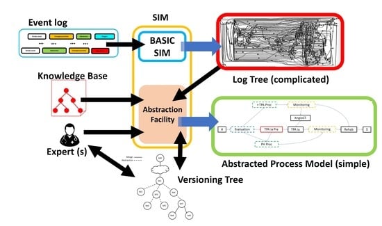
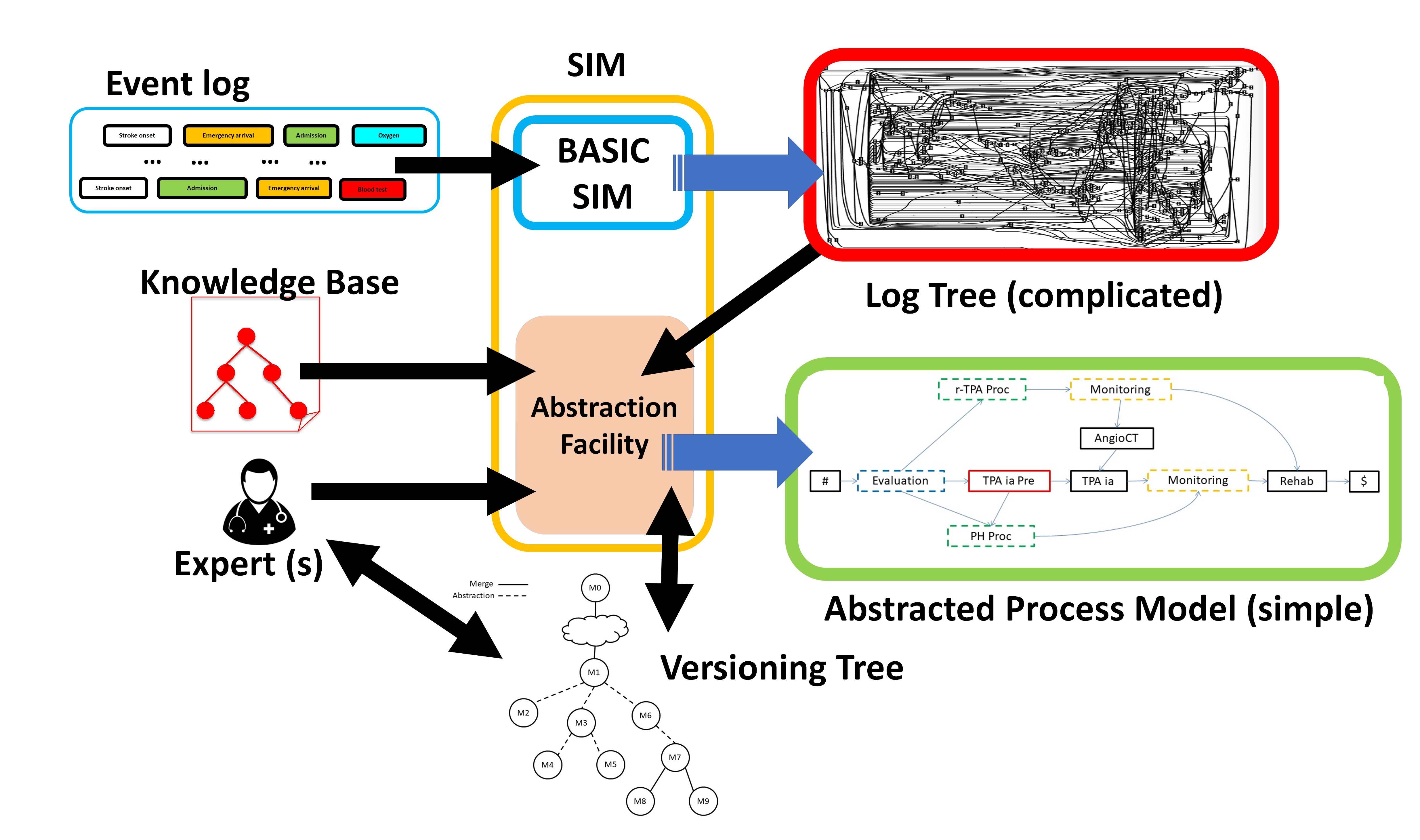
3.1. SIM: Generalities

The work proposed in this paper grounds on SIM, a novel miner supporting experts in balancing overfitting and underfitting in the process discovery task [2]. SIM supports process analysis through query and retrieval facilities, while semantic “merge” allows for building increasingly more generalized models. In addition, SIM provides fully automatic process discovery to be used when expert(s) knowledge is not available. A detailed description of SIM can be found in [3].
SIM consists of four main modules: (1) a mining module to build an initial process model (log tree); (2) a trace and path retrieval module to search for patterns in the log tree or in any generalized models, using a flexible and high-level query language; (3) a general “mergemodule supporting the generalization of process models by merging patterns in the current model; (4) a versioning module supporting the navigation through the history of the model evolution interaction by maintaining a versioning tree.
A work session in SIM starts running an algorithm (called Build-Tree), exploiting the traces in the log to mine a process model, called log tree, having both precision and replay fitness = 1. This means that each path in the log tree corresponds to at least one trace and that each trace can be successfully replayed in the log tree [4] (there are two main justifications for such a choice: (1) certain domains (e.g., medical applications) require a maximal precision or replay fitness; (2), in such a way, generalizations are driven “step-by-step” by experts (see [3] for a more detailed analysis of such motivations)). These features make the log tree a potentially overfitted model; therefore, the experts can apply merge operations to obtain progressively more generalized process models. Given a pattern of occurrences of a pattern of activities, described with our query language, the retrieval facility highlights all the occurrences of the pattern in the current model. Then, merge operations generate a new model by “unifying” these occurrences in a single pattern and updating the arcs accordingly. Notably, SIM offers different merge options, as well as the possibility of performing a selective merge on a subsect of the occurrences. Each process model can then be evaluated by experts both quantitatively (i.e., when a new model is generated, SIM evaluates its precision, replay fitness, and generalization) and qualitatively. Experts can evaluate each process model quantitatively, through measures such as precision, replay fitness, and generalization, and qualitatively with the help of the query and pattern retrieval facility. Furthermore, the versioning mechanism provided in SIM maintains the history of the obtained process models. Experts can navigate this history to select a particular model, obtain new versions from it, or backtrack to a previous one. Finally, the work session ends when the expert “approves” one of these models.
In the following, we briefly consider two specific aspects of SIM to understand the approach we propose in this paper: SIM’s formalism to represent the process model and SIM’s query language and query answering. Furthermore, in Section 6, we present extensions of the SIM’s versioning system to support knowledge-based abstraction versioning.

3.2. Representation Formalism (Process Model)

In SIM, as in many process mining approaches [1], we represent the process model as a direct graph, where nodes represent activities and arcs indicate the precedence between them. For the sake of compactness, in SIM, besides “simple” nodes, which represent an activity, we also support “any-order” nodes, labeled by a set of activities separated by “&” (e.g., A1&A2&A3) and representing the fact that such activities can be executed in any order (e.g., A1&A2&A3 denotes six different patterns of activities: A1A2A3, A1A3A2, A2A1A3, A2A3A1, A3A1A2, A3A2A1). When multiple arcs exit a node, the node itself represents an XOR splitting point.
Our running example starts with the log tree in Figure 1, which is the result of the Build-Tree operation on a real-world log, regarding the management of the stroke disease in the acute phase. This log contains 200 traces, expressed as sequences of 15 actions, on average, counting 14 different action types. Each trace describes the activities (tests, exams, and therapies) performed to treat the patient from her/his arrival in the stroke unit to her/his dismissal or transfer to another hospital ward. In the log tree in Figure 1, after the process starts (#), the blood test and computerized tomography (BT and CT, respectively) are executed in any order, followed by neurological evaluation (Eval). From the latter, an XOR split leads to three main paths: on the top, the sequence of activities is composed of magnetic resonance with contrast (MR DW), electrocardiogram (ECG), intravenous thrombolysis (r-TPA), ECG, CT, acetylsalicylic acid administration (ASA), and rehabilitation (rehab). The middle path is composed of ASA, angiographic CT (AngioCT), intra-arterial thrombolysis (TPA ia), ECG, CT, ASA, and rehab. At the bottom, the third path is composed of ECG, magnetic resonance (MR), ASA, anti-hypertensive drugs administration (Anti-HP), ECG, CT, ASA, and rehab. Additional paths stem from the top and middle main routes as XOR splits. A final dummy activity ($) is inserted to reunite all the paths of the log tree to the end of the process.

3.3. Query Language and Pattern Retrieval Facility

SIM provides a rich query language to define the patterns to be retrieved in the process models (actually, given a pattern (defined through SIM’s query language), SIM also supports the retrieval of all the traces corresponding to it from the log; however, such a facility is not relevant for the current paper), formally described by a Bacus-Naur Form (BNF) grammar. Notably, SIM’s query language supports the definition of “partially specified” patterns of activities. For example, the model in Figure 1 looks particularly complex, but some repeated paths could be merged to generalize it and improve readability. In particular, users can investigate the redundancy of the procedures typically repeated during stroke management. For instance, the administration of TPA ia with the activities normally associated with it (AngioCT and ECG) can be searched through a query involving the path: AngioCT, TPA ia, ECG. Similarly, a query containing the path ASA, Anti-HP, ECG could be helpful for highlighting the administration of anti-hypertensive drugs.
Since SIM’s query language is a regular language, in [4] we exploited finite state automata theory to perform pattern retrieval. Given a query (which defines a pattern), SIM automatically generates a non-deterministic finite automaton (NFA) to represent it (through an adaptation of Thompson’s algorithm [36]). Then, SIM directly performs pattern retrieval through a search algorithm, which gives the process model as an input to the NFA and provides as an output all the occurrences of the pattern (modeled by the NFA) in the process model (see [4] for more details). Figure 2 shows the result of the query about the path AngioCT, TPA ia, ECG on an excerpt of the model in Figure 1.
In Figure 2, the red nodes correspond to the activities matching the query.

3.4. Merge Operations

SIM provides a specific module to execute the merge operations. The module takes as input a set of paths in the model (as retrieved using the pattern retrieval facility) and merges them into a unique occurrence, generating a more readable model.
The analyst can choose to apply the merge operation to all the retrieved paths, or to one or more of the disjoint subsets of such paths.
Considering the running example started with the model in Figure 1, the user observes that some repeated paths can be merged to simplify the model, while maintaining the correctness of the process as much as possible. In particular, by applying the merge facility in different ways and exploiting the backtracking to evaluate the different solutions obtained, the user ends up with the process in Figure 3. This model is obtained by merging the paths containing the sequence TPA ia, ECG, CT, ASA at the top of the model in Figure 1, with the sequence ECG, MR, ASA, Anti-HP, ECG, CT, ASA at the bottom. Furthermore, the user merged the rehab activities, as a conclusion of each branch of the log tree.
Though less complex than the initial one (see Figure 1), the process in Figure 3 is still not easy to read, mainly due to the long chains of activities and interactions. Further simplifications are needed to clarify the main procedures.

4. A Model for the Domain Knowledge

Many approaches to process model discovery, including our SIM system [3], only rely on a list containing the possible activities that may appear in the traces, and, thus, in the process model. While such approaches are the only possible ones in contexts where no a priori knowledge is available, in other contexts, wide bodies of knowledge exist about the processes operating in the domain and about the relationships between the activities they involve. In many cases, such knowledge is organized into knowledge bases called ontologies, which may include descriptions of the activities, in terms of their properties (e.g., resources, goals, effects, and side-effects) and of the relationships between them (e.g., ISA, part-of, and causes). This is the case of the medical domain, for instance, where well-known and widely used ontologies are available (e.g., SNOMED [38], ATC [39]), which are often based on widely adopted AI frameworks, such as OWL [40].
When such ontological knowledge is available, it is worth using it within process mining. The main goal of this paper is to show how (a part of) such knowledge can be integrated into process model discovery to support experts in the identification of a suitable process model with the desired level of abstraction. In particular, given their importance and generality, in this paper, we focus on two forms of knowledge: (i) ISA relationships and (ii) part-of relationships. Specifically:
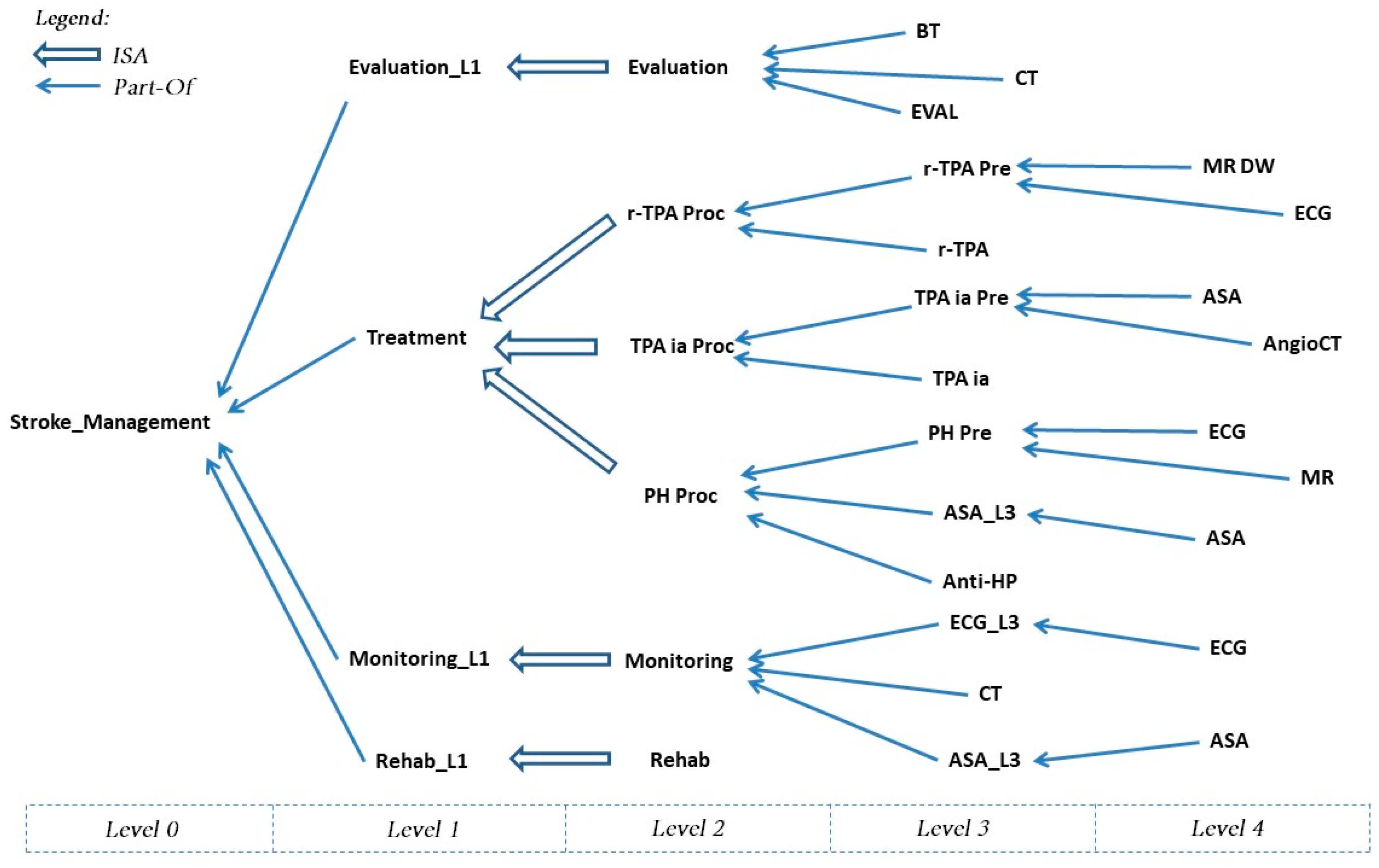
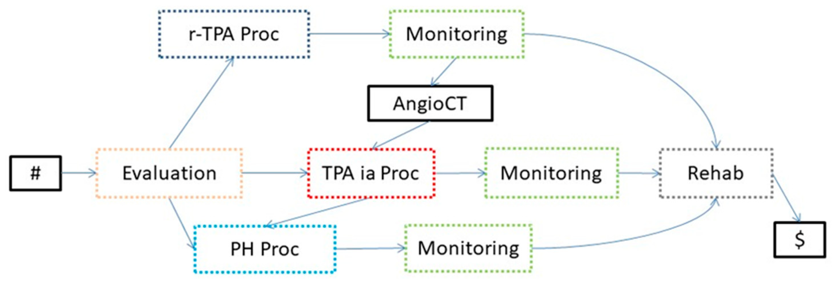
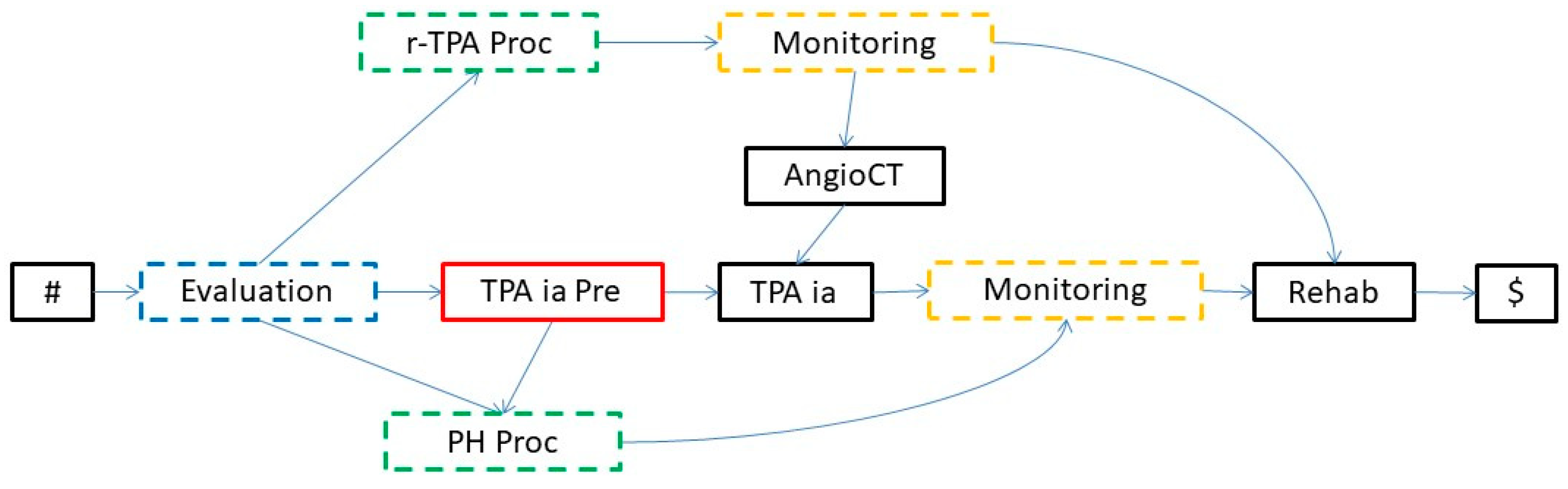
  • ISA relationships are (subtype–supertype) subsumption relations between classes (of entities; in our case, of activities): a class of activities A is a superclass of B when A’s specification implies B’s specification. For instance, in the knowledge base in Figure 4, intravenous thrombolysis (r-TPA Proc), intra-arterial thrombolysis (TPA ia Proc), and pharmacological therapy (PH Proc) are subclasses of Treatment.
  • Part-of relationships are partonomic (i.e., part-whole) relations between classes; in the case of activities, they relate a class A with the classes C1,…,Cn composing it, modeling the decomposition of composite activities into the sub-activities composing them. For instance, in the knowledge base in Figure 4, Stroke_Management is composed of four (sub-)activities: Evaluation_L1, Treatment, Monitoring_L1, and Rehab_L1 (rehabilitation).
Notably, the ISA and part-of relations provide a hierarchical representation of activities, in the form of a direct acyclic graph (DAG), that we call an ontological knowledge base (KB). For the sake of simplicity (and with no loss of generality), we suppose that the KB hierarchy has a unique (“catch-all”) starting node. Notably, the choice of a DAG (instead of a tree) allows us to represent the hierarchical knowledge more compactly, admitting, e.g., that a given node (activity) is part of more than one node (activity). In the rest of the paper, we adopt the following terminology.
Terminology. We term “abstractionlevels” (levels, for short) as the levels in the hierarchy. We say that the starting node of the KB hierarchy is at level zero, its direct descendants (termed “direct sons”) are at level one, and so on. We partition the nodes in the hierarchy into three types:
  • ISA nodes”, i.e., nodes N, whose sons in the KB hierarchy are in an ISA relationship with N;
  • Part-Of nodes”, i.e., nodes N, whose sons in the KB hierarchy are in a part-of relationship with N;
  • ground nodes”, i.e., nodes that have no sons in the KB hierarchy (representing the ground non-decomposable activities appearing in the input traces in the log).
Note that a specific node can only appear at a given level of the KB (since it represents an activity expressed at a precise level of abstraction). On the other hand, we do not make any assumption about the length of the paths in the hierarchy, so that ground nodes can occur at all the levels—except level zero.
In Figure 4, we show (part of) the ontological KB modeling the main tasks in the management of ischemic stroke for our running example.
In particular, stroke management in the acute phase, according to medical knowledge (ISO 2016) (https://www.iso-stroke.it/?page_id=200 accessed on 24 October 2022), is comprised of:
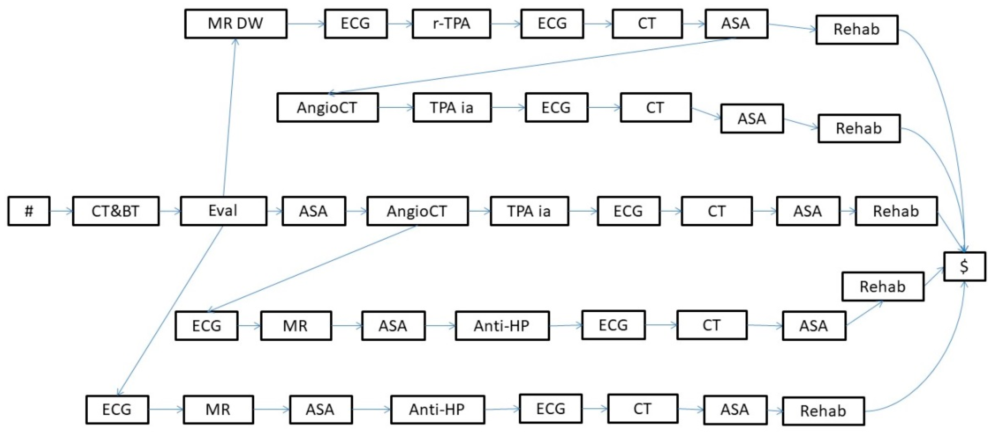
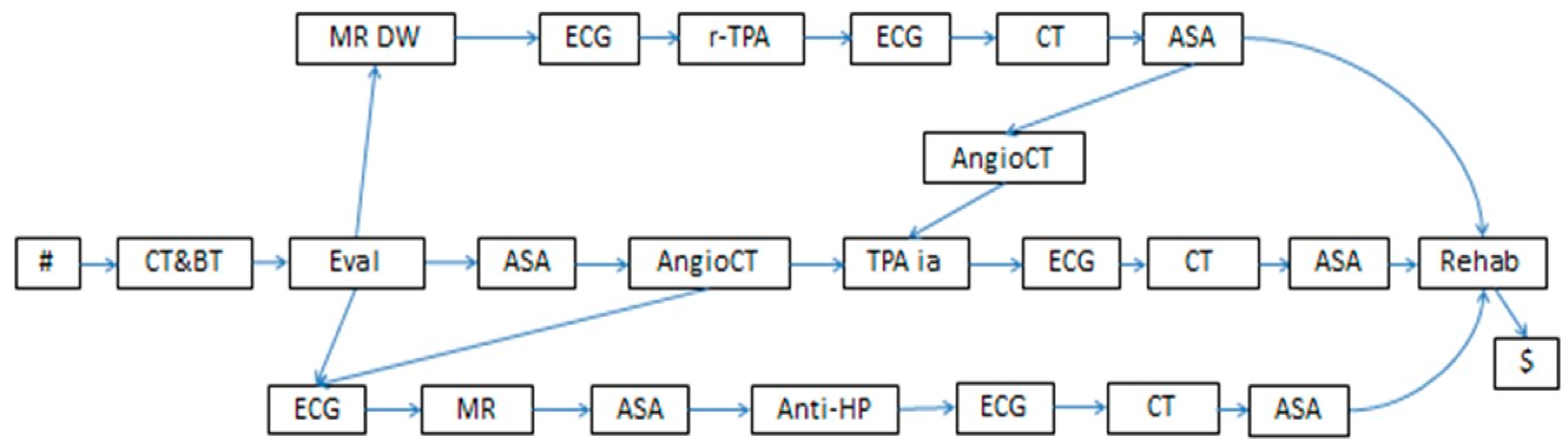
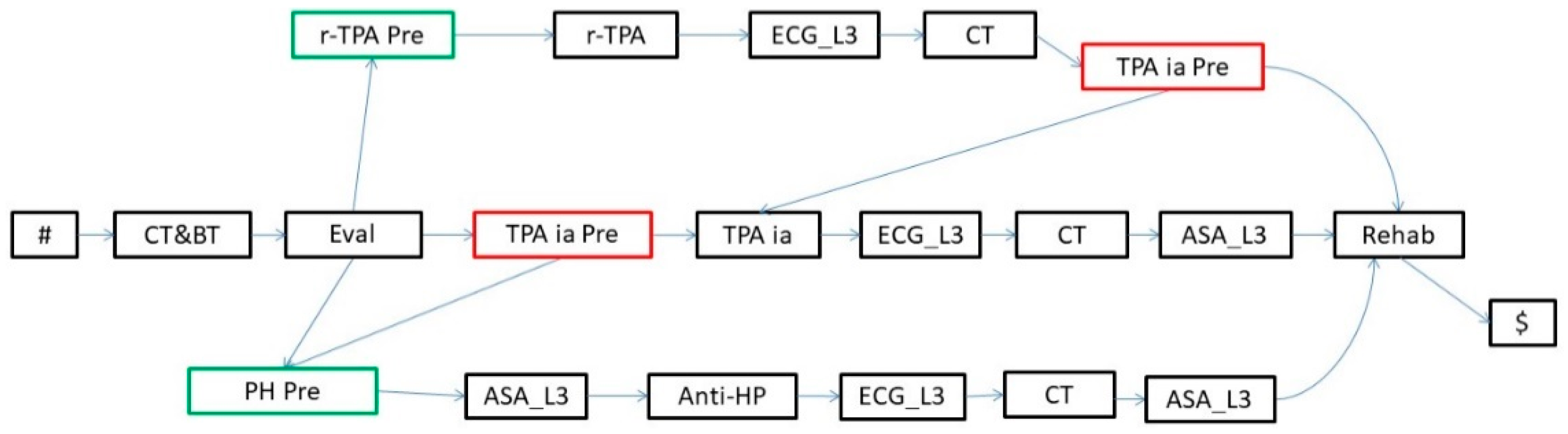
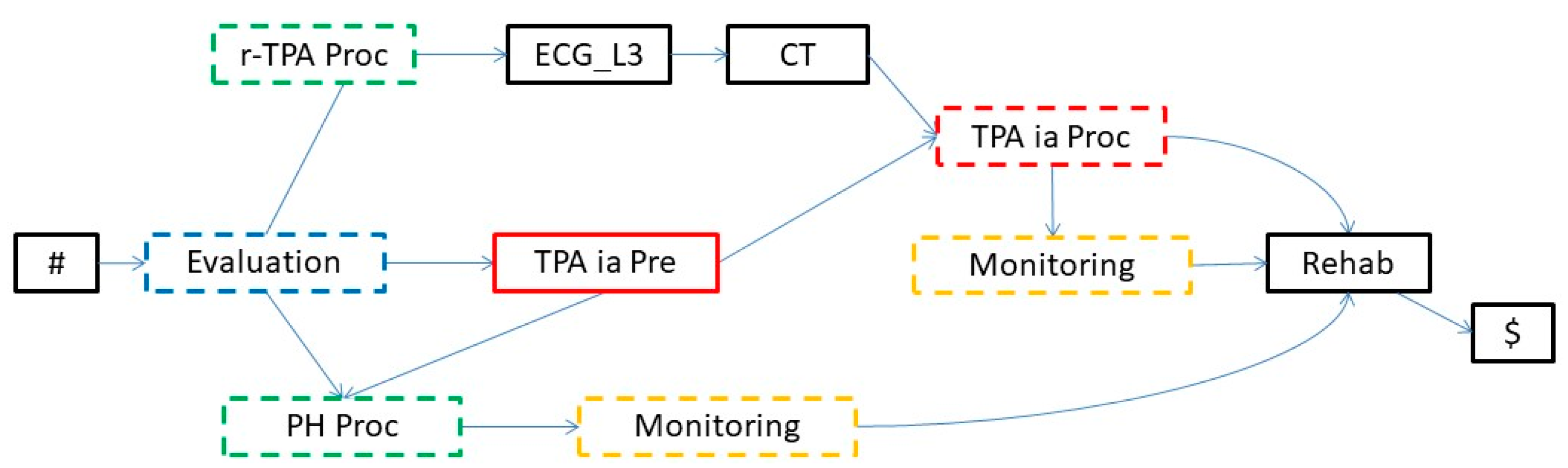
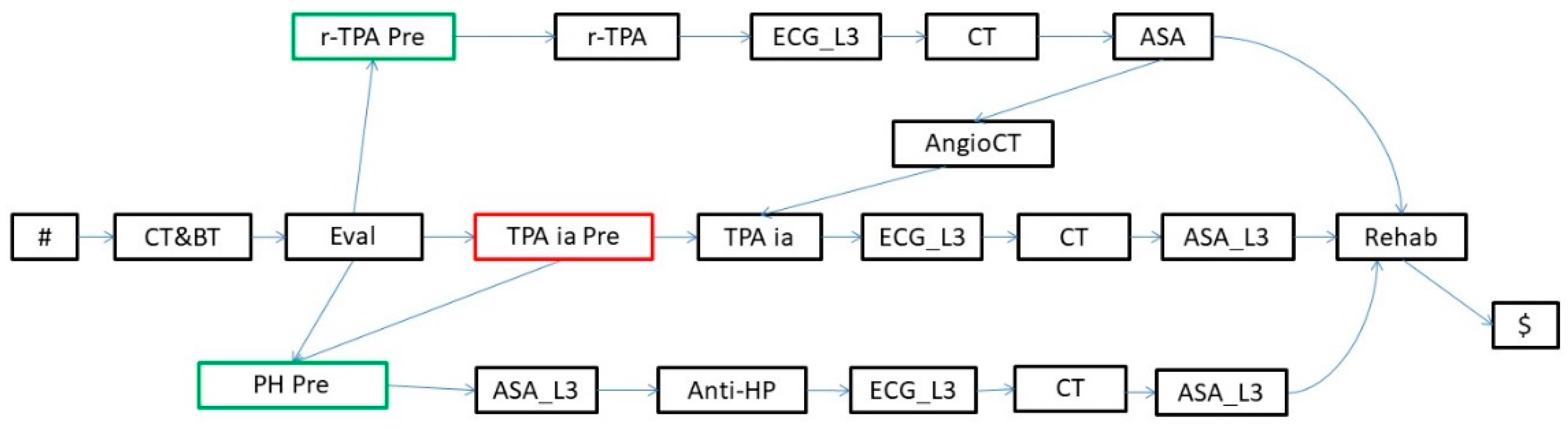
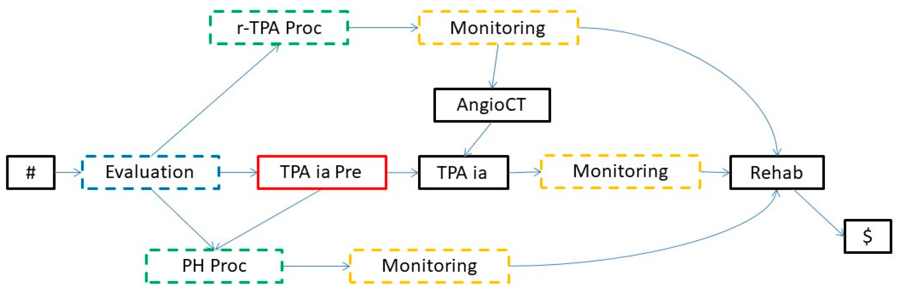
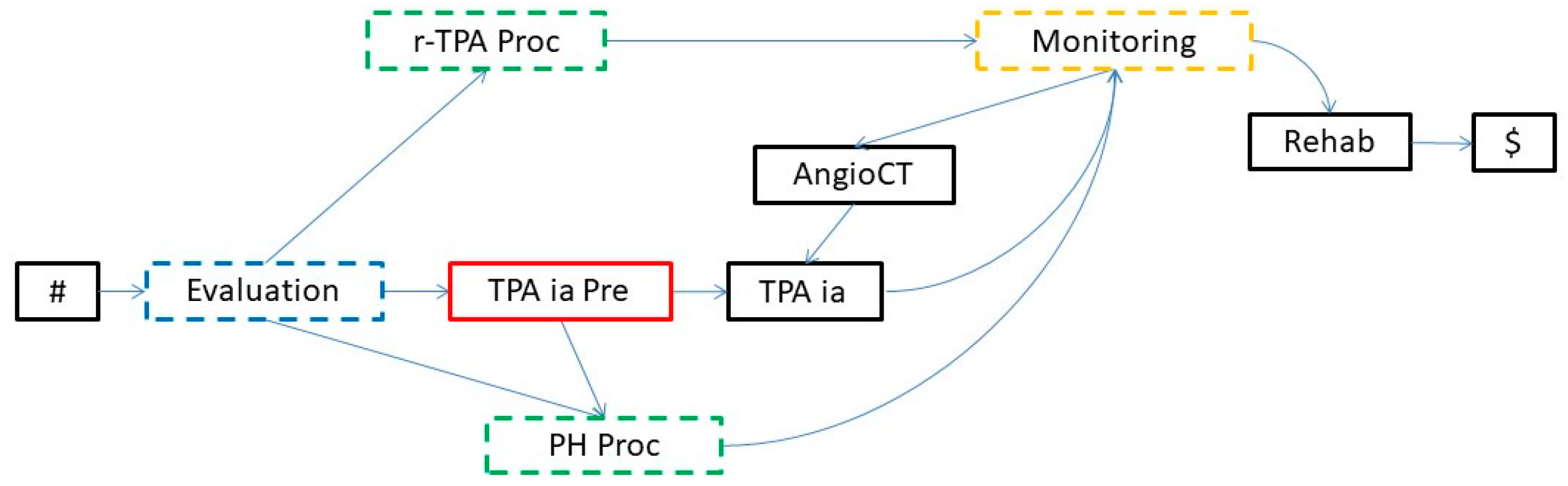
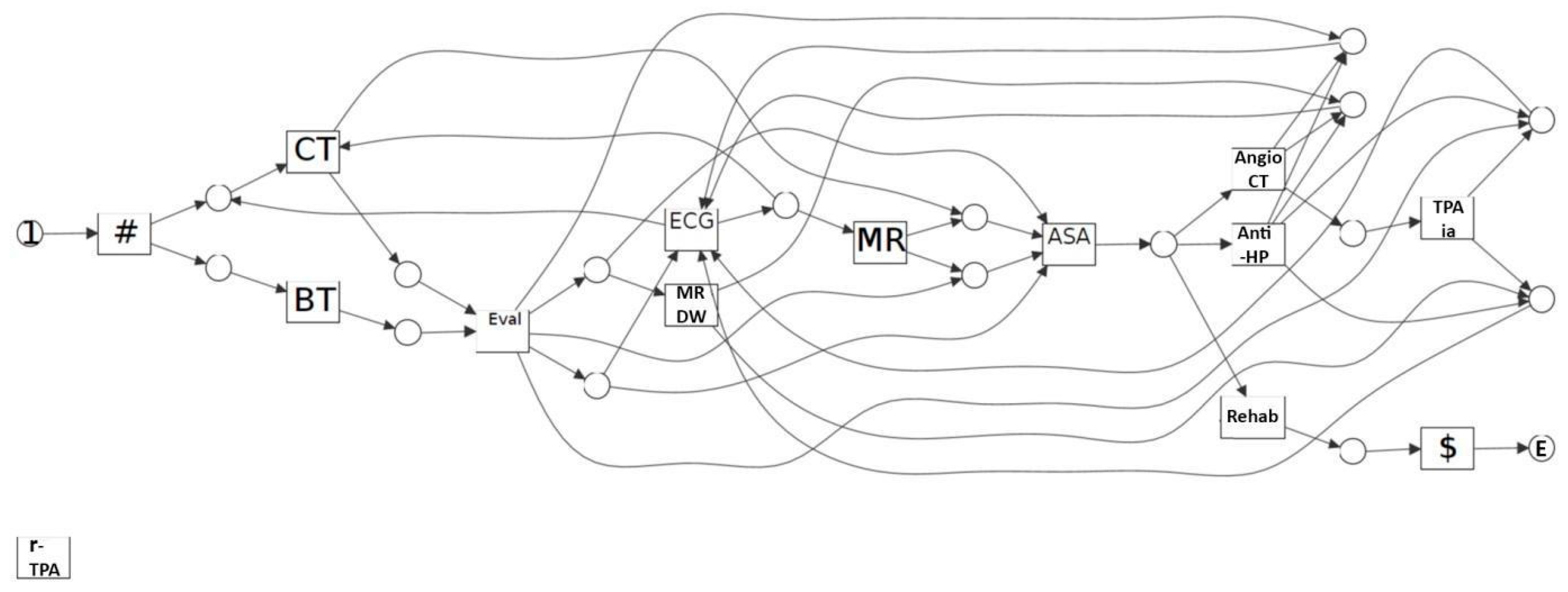
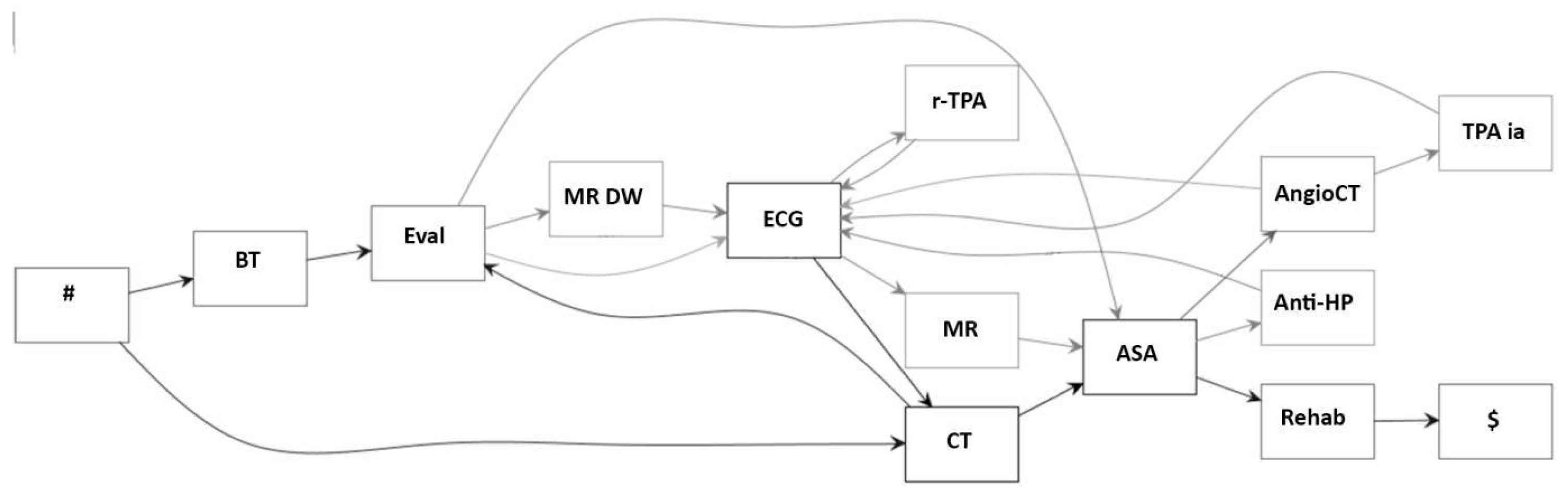
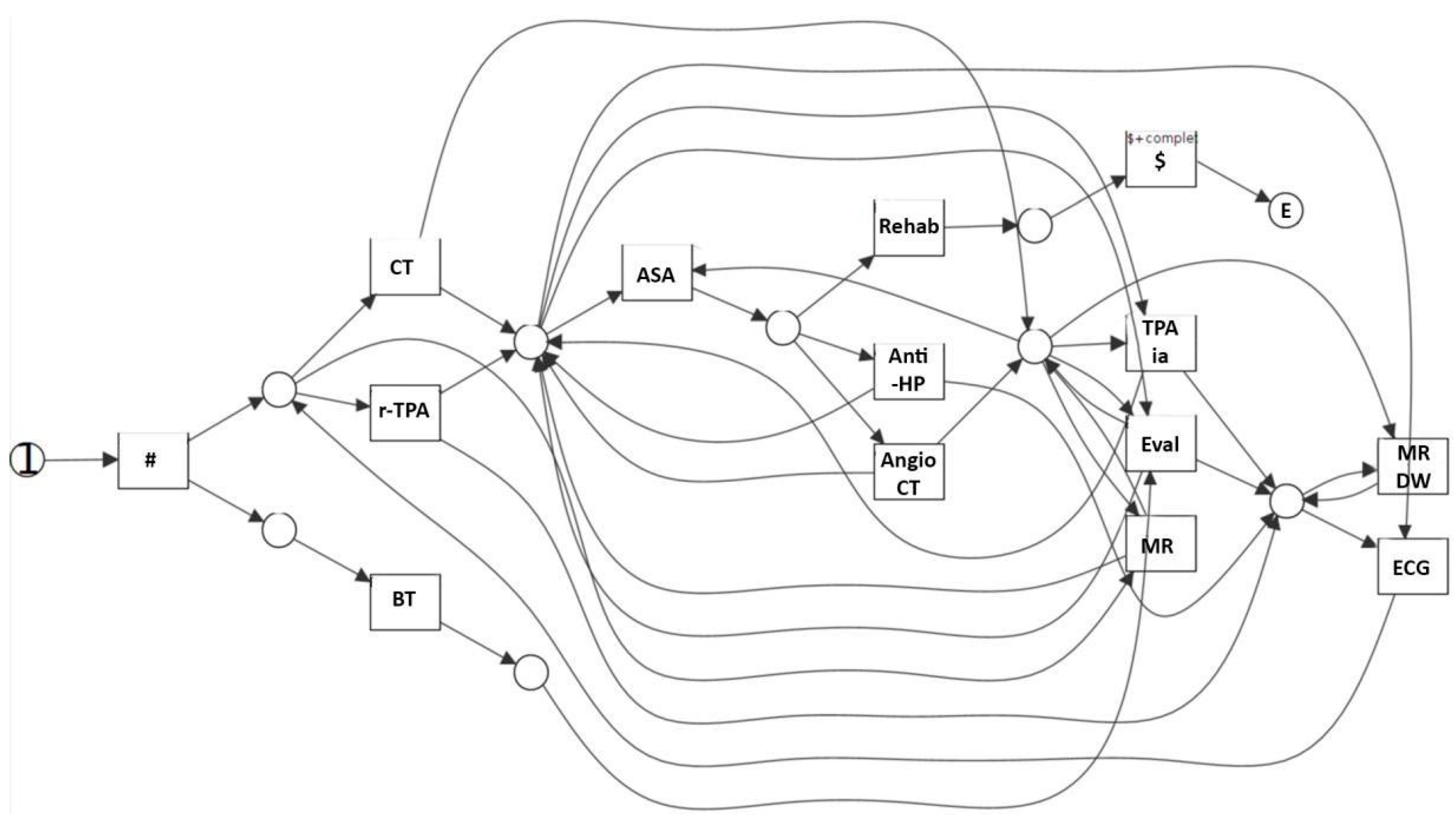
  • An evaluation of the patient’s condition (Evaluation in the KB in Figure 4, further abstracted as Evaluation_L1 at level 1), obtained through tests and instrumental exams, such as blood test and computerized tomography (BT and CT in the KB, respectively) and a neurological evaluation (EVAL).
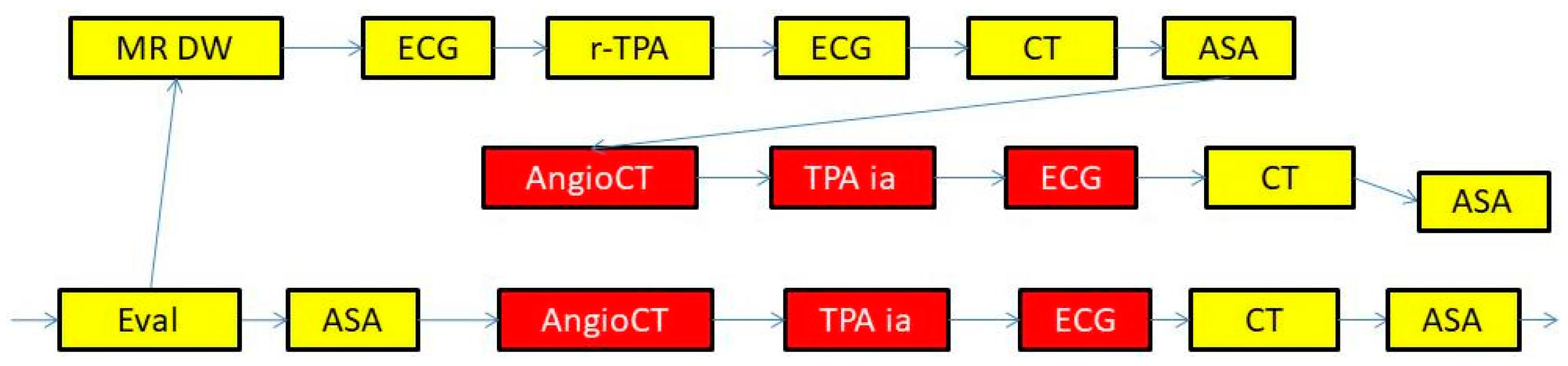
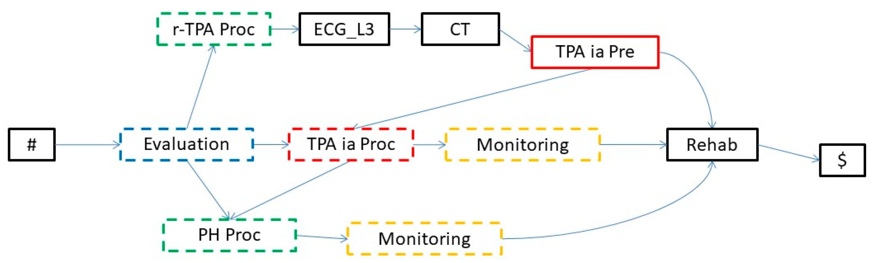
  • The treatment (Treatment in the KB in Figure 4) can consist of intravenous thrombolysis (r-TPA Proc), intra-arterial thrombolysis (TPA ia Proc), or pharmacological therapy (PH Proc). In turn, r-TPA Proc begins with a preparation phase (r-TPA Pre), composed of magnetic resonance with contrast (MR DW) and electrocardiogram (ECG) and continues with r-TPA drug administration (r-TPA). Similarly, TPA ia Proc starts with TPA ia Pre, composed of some preliminary steps (acetylsalicylic acid administration (ASA) and AngioCT), and continues with the TPA ia treatment itself. PH Proc, instead, starts with a preparatory phase (PH Pre), composed of tests such as ECG and magnetic resonance (MR). ASA (further abstracted as ASA_L3 at level 3) and anti-hypertensive drugs (Anti-HP) are then administered.
  • A monitoring phase (Monitoring, further abstracted as Monitoring_L1 at level 1). Monitoring is usually performed through tests such as ECG (further abstracted as ECG_L3 at level 3), CT, and the administration of ASA.
  • A rehabilitation phase (Rehab, further abstracted as Rehab_L1 at level 1).

5. Knowledge-Based Abstraction Operations

In this section, we first provide a “high-level” introduction to the problems to be faced by the abstraction algorithms, and the different main options we want to grant (Section 5.1); then, we detail two classes of algorithms: fully automatic algorithms (Section 5.2) and interactive (with domain experts) algorithms (Section 5.3).

5.1. Main Issues

Abstraction, according to the terminology we specified in the Introduction (Section 1), allows one to “move upwards”, and thus obtain a higher-level view of a process model, where details are ignored. In the case of ISA relationships (e.g., “r-TPA Proc” ISA “Treatment”), a specific activity (or class of activities) can be replaced by the class of activities containing it (e.g., “r-TPA Proc” can be abstracted into “Treatment”). In the case of part-of relationships (e.g., {“r-TPA Pre”, “r-TPA”} part-of “r-TPA Proc”), a set of activities (or classes of activities) can be replaced by the class of activities they constitute (e.g., “r-TPA Pre” and “r-TPA” can be replaced by “r-TPA Proc”).
Informally, in a process model PM (which is represented, in our approach, by a graph), an abstraction step considering an ISA relationship A1 ISA A consists of:
(ISA_1) the retrieval in PM of all the occurrences of A1;
(ISA_2) the replacement of such occurrences with A.
While an abstraction step considering a part-of relationship {A1, …, Ak} part-of A consists of:
(POF_1) the retrieval in PM of all the occurrences of paths containing all and only the nodes A1, …, Ak (all the possible orderings of A1, …, Ak are admitted);
(POF_2) the replacement of such occurrences with A.
Notably, the definition of step POF_2 above involves the treatment of two critical issues:
(i1) how to manage “intersecting paths”, and
(i2) how to deal with “conflicts”.
Definition 1.
Given a path p = <A1 → A2 → … → Ak> in graph G, we call the intersecting paths all those paths in G that “cross” P, i.e., that have an “entering” arc I → Ai (1 ≤ i ≤ k, and I ∉ P) and an “exiting” arc Aj → O (1 ≤ j ≤ k, and O ∉ P), except paths where, simultaneously, i = 1 and j = k (i.e., paths fully including P are excluded).
For example, given the graph in Figure 5A, paths … I1 → A1 → A2 → O1 and … I2 → A2 → O1 are, among many others, intersecting paths of p = <A1 → A2 → … → Ak>.
The easiest (and, probably, most natural) way of executing the replacement of a path P with a single node A involves the substitution of the whole path P with A, the re-addressing of all the arcs entering any node in P as arcs entering A, and the re-addressing of all the arcs exiting any node in P as arcs exiting A. The result of the application of such a form of replacement to path p = <A1 → A2 → … → Ak> in the example in Figure 5A is shown in Figure 5B. Notably, however, while moving from the process model in Figure 5A to the one in Figure 5B, one obtains a more compact and abstract model, but loses the information provided by the intersecting paths. For instance, the new model does not contain the path … I2 → A2 → O1 anymore. In some cases, domain experts may recognize that one or more intersecting paths are very important. In our interactive approach, we want to provide experts with the possibility of performing the abstraction, while preserving the “relevant” intersecting paths. For example, Figure 5B shows the result of the abstraction operation preserving the path … I2 → A2 → O1
The problem of “conflicts” arises whenever the paths to be abstracted intersect with each other. Consider, e.g., the abstraction {A1, A2, A3} part-of A in the process model PM in Figure 6A. There are three occurrences of paths consisting of the {A1, A2, A3} nodes. However, such paths intersect with each other, so that there is a “conflict”: not all of the three abstractions can be performed. In our approach, we want to grant experts the possibility of choosing which one(s) of the conflicting abstractions have to be performed. As an example, in Figure 6C, we show the case where the abstraction is performed on the occurrences of the paths on the left and the right of the graph.
Finally, SIM grants domain experts the possibility to selectively apply the merging operations on the process model. We want to also retain selectivity in the new version; thus, in the interactive algorithms, we provide users with the possibility of selecting which occurrences of the retrieved paths a given abstraction have to be performed.
Before moving to our abstraction algorithms, it is worth noticing that, aiming at generality, we have developed our approach considering different possibilities:
  • Interactive vs. automatic application of the abstraction;
  • Activity-based abstractions vs. level-based abstractions.
Regarding the first point, though we aim at supporting interactive knowledge-based abstraction (Section 5.3), for the sake of generality, we also provide algorithms to perform abstraction in a fully automatic way (Section 5.2).
Regarding the second point, in activity-based abstractions, the expert(s) selects an activity A in the KB, and the process model is automatically/interactively updated by substituting A to all the occurrences of the patterns constituting a subsumption/decomposition of A (in the KB). On the other hand, in level-based abstractions, the expert(s) selects a level L in the KB, and the process model is automatically/interactively updated by considering each activity A at level L in the KB and by substituting A to all the occurrences of the patterns expressing its subsumptions/decompositions in the KB itself. The rationale behind this facility is the one of homogeneously converting a given input process model at a desired hierarchical abstraction level. For the sake of brevity, in the paper, we mainly focus on activity-based abstraction, giving hints about how the abstraction algorithms can be extended/modified to support level-based abstraction, as well.

5.2. Automatic Abstraction Operators

We now focus on the operations we provide to perform fully automatic abstraction. In this case, the analysts simply call for one of such abstraction operations, and then the operation is automatically executed, with no further interaction. In such a modality, intersecting paths are not considered, and conflicts are solved automatically by performing the abstractions in the ordering they are retrieved by the algorithms (FIFO policy). On the other hand, the interactive procedures will be described in Section 5.3.
Algorithms 1 and 2 below describe the procedures we have devised to perform activity-based abstraction on a given process model in an automatic way.
In detail, the input to the procedure AutomaticActAbstract in Algorithm 1 is composed of various parameters:
  • KB: the starting node of the ontological KB;
  • AN: the node the user wishes to abstract;
  • PM: the current process model (represented as a graph), which needs to be abstracted, in regard to the instances of node AN;
  • AbstrST: a table maintaining the information of what KB nodes have already been considered for abstraction.
The output of the procedure is the process model modified by performing the required abstractions.
The procedure AutomaticActAbstract first checks (line 2) whether the requested abstraction is legal (as checked by the procedure LegalAbstraction?), a condition that holds that, when AN is not a ground node, it has not been already abstracted, and it is not a descendant of an already abstracted node (to this end, AbstrST is checked). If the abstraction is not legal, a warning is generated (line 3). Otherwise, the PerformAutAbstraction recursive procedure is called (line 5).
Algorithm 1: pseudocode of automatic activity-based abstraction algorithm.
1: AutomaticActAbstract (KB, AN, PM, AbstrST)
2: if (not LegalAbstraction? (KB, AN, AbstrST)) then
3:   signal warning
4: else
5:   PerformAutAbstraction (KB, AN, PM, AbstrST)
6: endif
In turn, PerformAutAbstraction (see Algorithm 2) takes KB, AN, PM, and AbstrST as input.
Algorithm 2: pseudocode of the recursive automatic abstraction algorithm.
1: PerformAutAbstraction (KB, AN, PM, AbstrST)
2: if (not Abstracted? (AN, AbstrST) and not GroundNode? (KB, AN)) then
3:   if IsaNode? (KB, AN) then
4:     for each Node in GetSons (KB, AN) do
5:       PerformAutAbstraction (KB, Node, PM, AbstrST)
6:       Substitute (Find (Node, PM), AN, PM)
7:     end for
8:     Add (AN, AbstrST)
9:   else
10:       if PartOfNode? (KB, AN) then
11:         for each Node in GetSons (KB, AN) do
12:           PerformAutAbstraction (KB, Node, PM, AbstrST)
13:     end for
14:     Substitute (Exec (AN, PM), AN, PM)
15:     Add (AN, AbstrST)
16:     end if
17:   end if
18: end if
In the recursive procedure, the base case is represented by the check at line 2: PerformAutAbstract will end if AN has already been considered for abstraction (as checked by the procedure Abstracted?, which verifies whether AN is present as an entry in the abstraction table AbstrST) or it is a ground node (as checked by the procedure GroundNode?).
In the general case, two situations are possible.
The first situation (lines 3–8) occurs when AN is an ISA node. In such a case, the algorithm recursively calls PerformAutAbstraction on each son of AN (line 5) and then substitutes AN for each son (identified through the procedure Find) everywhere in the model (line 6). Then, through the function Add, the algorithm adds AN to the abstraction table AbstrST, so that it will not be considered again for abstraction in the future (line 8).
The second situation (lines 9–17) holds when AN is a part-of node. In such a case, it is necessary to recursively call PerformAutAbstraction on each son (line 12) and then substitute AN to its partonomic decomposition everywhere in the model PM (line 14). Operatively, abstraction is realized by executing the query, which is built based on AN in the KB. In particular, the procedure Exec executes the query on PM and gives all the occurrences of the partonomic decomposition pattern as output. The procedure Substitute will then substitute all the occurrences with AN. Specifically, given an occurrence of the partonomic decomposition pattern, Substitute inserts the new node AN in the model, redirects all the incoming and outgoing arcs of the occurrence to AN, and removes all the original nodes in the partonomic decomposition pattern. Then, through the function Add, also in this case, the algorithm adds AN to the abstraction table AbstrST, so that it will not be considered again for abstraction in the future (line 15).
Notably, level-based automatic abstraction can be simply obtained by iterating the above procedures on all the activities at the input level in the KB.

5.2.1. Automatic Abstraction in Our Running Example

The process model in Figure 3, although less complex than the initial one (see Figure 1), is still not easy to read at first glance, mainly due to the long chains of activities and interactions. A higher-level view of the main procedures performed in this process can be useful for facilitating the interpretation. Such a view can be obtained thanks to the KB presented in Figure 4. The user can exploit the KB in a naïve way, trying, as a first option, the execution of the abstraction algorithm in a fully automatic mode, indicating, e.g., level 2 of the KB as the desired abstraction level. Notably, at level 2, all the medical procedures (patient evaluation, therapeutic procedures involving both preparatory and intervention phases, patient monitoring, and rehabilitation) are defined in their more general form. After running the automatic algorithm, the system provides the model in Figure 7 as output.
The model in Figure 7 is much more readable and clearly shows most of the main procedures performed for the treatment of patients. However, the user recognizes, in this model, a path in which all three treatments (r-TPA proc, TPA ia proc, and PH proc) are potentially performed on a single patient, with a transition from the r-TPA proc procedure (upper branch after Evaluation) to the TPA ia proc procedure, and finally, to the pharmacological procedure (PH Proc, lower branch). This is not correct from the medical viewpoint. Thus, the user needs to backtrack to the model in Figure 3 to apply alternative abstraction strategies, different from the automatic one, as discussed in the following section.

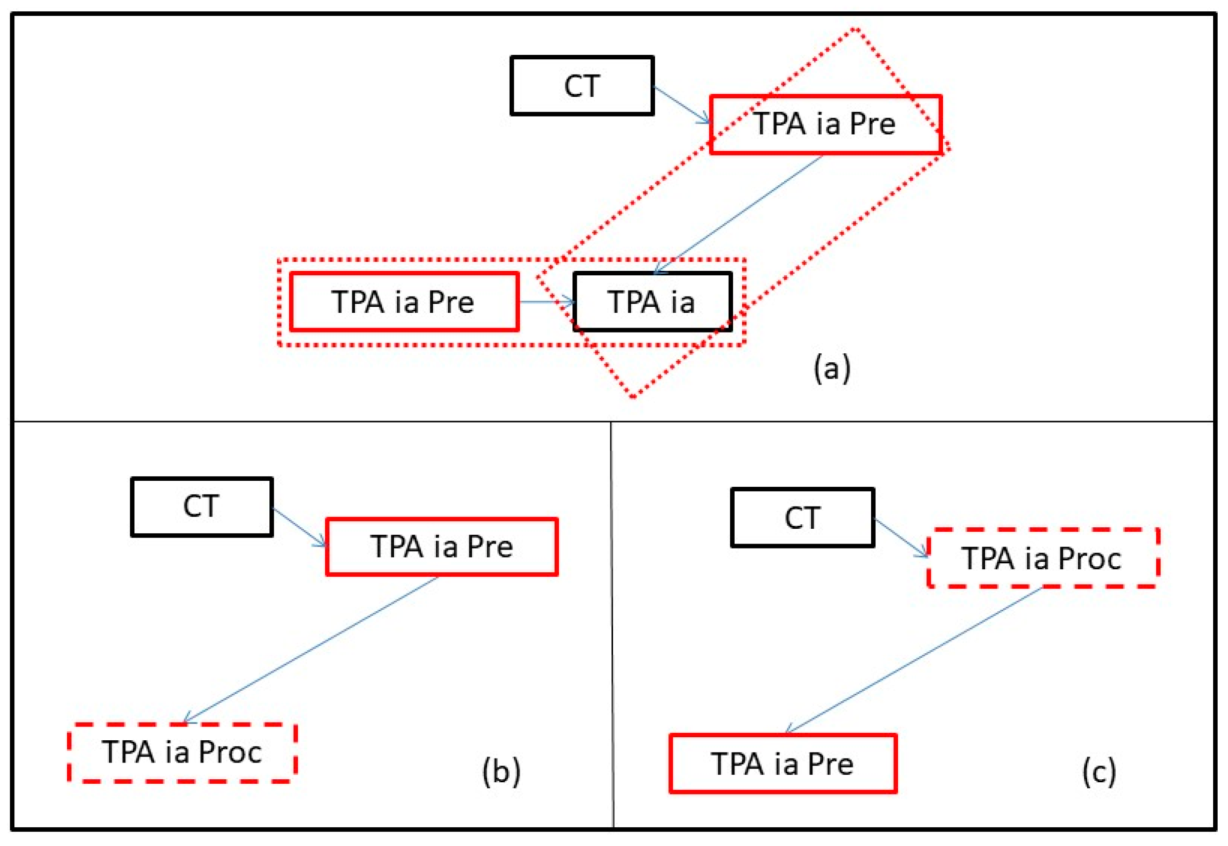
5.3. Interactive Abstraction Operators

The abstraction algorithms in 5.2 perform the abstractions (chosen by the analysts) in a fully automatic fashion. They do not consider intersecting paths and automatically solve conflicts. However, analysts may want to play an active role in the abstraction process, by having the possibility of (i) preserving some intersecting paths, (ii) solving conflicts, and (iii) selectively performing abstractions. The algorithms introduced in this section provide analysts with such possibilities.
The main algorithm we have defined to cover the above task is called InteractiveActAbstract (see Algorithm 3). It takes the following parameters as input:
  • KB: the starting node of the ontological KB;
  • AN: the node of KB the user wishes to abstract;
  • PM: the current process model, which needs to be abstracted, in regard to the instances of node AN;
  • AbstrST: the abstraction symbol table, which keeps track of what KB nodes, have already been considered for abstraction in PM.
Intuitively, the InteractiveActAbstract algorithm applies the AN abstraction node of KB to the PM model, considering the previous abstraction activities (i.e., stored in AbstrST) and interacting with the user to manage intersecting paths and conflicts.
Algorithm 3: pseudocode of the interactive activity-based abstraction algorithm.
1: InteractiveActAbstract (KB, AN, PM, AbstrST)
2: D ← DistanceGround (KB, AN)
3: for LD-1 to 0 do
4:   Nodes ← GetNodesLevel (KB, AN, L)
5:   Paths ← {}
6:   for each N in Nodes do
7:     if (not GroundNode? (KB, N) and not Abstracted? (N, AbstrST)) then
8:       if IsaNode? (KB, N) then
9:         for each CN in GetSons (KB, N) do
10:             Substitute (Find (CN, PM), N, PM)
11:          end for
12:           Add (N, AbstrST)
13:         else
14:           if PartOfNode? (KB, N) then
15:             PathsPaths ⋃ <Exec (N, PM), N>
16:           Add (N, AbstrST)
17:         end if
18:       end if
19:     end if
20:     end for
21:     if (not IsEmpty? (Paths)) then
22:       PartitionSet ← Partition (Paths)
23:       for each Set in PartitionSet do
24:         SolveAndAbstract(Set, PM)
25:       end for
26:     end if
27: end for
This algorithm iterates (lines 3–27) over all descendant nodes of AN located at the same level in a bottom-up way (i.e., from the most distant ones from AN in the KB), starting from “pre-ground” nodes (i.e., nodes located one step just before ground nodes) up to the AN node, and performs abstractions level-by-level. The function DistanceGround evaluates the maximum level D to the ground nodes (paths in the ontological KB may have different lengths); then, the “for loop” at lines 3–27 starts iterating from level D-1, as ground nodes are not considered for abstraction.
Specifically, at each iteration, the algorithm retrieves all nodes Nodes at a certain level L from AN through the function GetNodesLevel (line 4) and considers them for abstraction, according to their type. In particular, for each retrieved node N, first, the algorithm checks whether the node can be considered for abstraction; to this aim, it checks whether N is either a ground node or has already been considered for abstraction (as checked in line 7 by the GroundNode? and Abstracted? functions, respectively).
If the abstraction for N is possible, two cases are possible. In the case N is an ISA node (lines 9–12), the algorithm just substitutes all the sons (i.e., subtypes) of N that occur in the process model PM with N itself (line 10), and through the function Add, the algorithm adds N to the abstraction table AbstrST to indicate that it has already been considered for abstraction (line 12). In the case N is a part-of node (lines 15–16), the algorithm, through the function Exec (the same one used by Algorithm 2), looks for all paths P in PM that match the part-of relation defined by N and adds them to the set Paths (line 15) as a pair <P, N>; the algorithm also updates the abstraction table AbstrST to indicate that N has been considered for abstraction (line 16).
After considering all nodes in Nodes, the algorithm partitions the elements of Paths (i.e., the paths that could be abstracted) into non-overlapping sets (line 22). Notably, unitary sets can also be part of the output of this step (to consider abstraction paths that do not intersect any other abstraction path in the process model). Finally, for each resulting set from the above partitioning, the algorithm manages (interactively with the analysts) the related abstractions by invoking the SolveAndAbstract algorithm (lines 23–25).
The purpose of the SolveAndAbstract algorithm (see Algorithm 4) is to abstract a set of paths T in a given process model PM, which can be abstracted to specific part-of nodes by interacting with the user to solve conflicts, managing intersecting paths, and possibly choosing not to perform the abstraction of specific paths (to support selective abstraction). The algorithm takes the following parameters as input:
  • T: a set of intersecting paths that needs to be abstracted; each element is a pair <P, AN>, where P is a path of the process model PM (see below), and AN is the part-of node, in which P may be abstracted;
  • PM: the current process model that needs to be abstracted.
Algorithm 4: pseudocode of the conflict resolution and abstraction algorithm.
1: SolveAndAbstract (T, PM)
2: A ← AskAbstractions (T, PM)
3: PathsToKeep ← AskPaths (A, PM)
4: NodesToDelete ← {}
5: ArcsToDelete ← {}
6: for each <X, AN> in A do
7:   N ← CreateNode (AN, PM)
8:   CreateArcs (N, GetInArcs (X, PM), GetOutArcs (X, PM))
9:   NodesToDeleteNodesToDelete ⋃ GetPathNodes (X)
10:   ArcsToDeleteArcsToDelete ∪ GetInArcs (X,PM) ∪ GetOutArcs (X, PM) ⋃ GetPathArcs (X)
11: end for
12: for each P in PathsToKeep do
13:   NodesToDeleteNodesToDelete—GetPathNodes (P)
14:   ArcsToDeleteArcsToDelete—GetPathArcs (P)
15: end for
16: Delete (PM, NodesToDelete, ArcsToDelete)
The algorithm starts with a call to the AskAbstractions procedure (line 2), which asks the analysts to select zero or more paths in T to be abstracted (such paths are stored in A; line 2). Notably, the analysts can: (i) select only paths which have no intersection between them, and (ii) select no paths in T (i.e., choose to not perform any abstraction in T; please remember that T may also be a unitary set, in cases where an abstraction path has no intersection with any other abstraction paths).
In such a way, AskAbstractions accomplishes user-driven conflict resolution and implements selectivity in the application of abstractions. On the other hand, the procedure AskPaths in line 3 asks analysts which intersecting paths they want to preserve (if any) and stores them in the PathsToKeep.
Subsequently (lines 6–11), the algorithm performs the abstractions in A. Specifically, for each path X to be abstracted into AN, the algorithm creates in PM a new node N with the same label of AN (line 7) and connects it to all nodes of PM that are connected with one or more nodes of X (i.e., for all edges (U,V)), such that for U ∉ X and V ∈ X, the algorithm creates a new edge (U,N), and for all edges (U’,V’), such that U’ ∈ X and V’ ∉ X, the algorithm creates a new edge (N,V’)) (line 8). It is worth noticing that, to prevent the deletion of some nodes/edges that the user has asked to preserve, the removal of nodes and edges of an abstracted path is delayed to the end of the abstraction process; to keep track of them, the algorithm uses two distinct sets, namely NodesToDelete and ArcsToDelete, where, for each abstracted path X, it collects all nodes of X and all edges (U,V) that are either incoming to X (i.e., U ∉ X and V ∈ X) or outgoing from X (i.e., U ∈ X and V ∉ X) or internal to X (i.e., U,V ∈ X) (lines 9–10), respectively.
Then, the algorithm removes from the NodesToDelete and ArcsToDelete sets those nodes and edges belonging to paths that the user has decided to maintain (lines 12–15), and finally, it removes from PM all nodes in NodesToDelete and all edges in ArcsToDelete sets (line 16).
The InteractiveActAbstract algorithm performs abstractions concerning a single activity (i.e., it performs an activity-based abstraction), but it can be easily extended to take a given level of KB (instead of a single abstraction node) as input, which is used to retrieve all the nodes at that level in the KB, thus obtaining a level-based interactive abstraction algorithm. Specifically, the DistanceGround function (line 2 of Algorithm 3) must be modified to work with multiple abstraction nodes as input, instead of only one (i.e., the first input parameter, which is a node, must be replaced with a set of nodes) and to evaluate the maximum distance from any of the input nodes to a ground node. Similarly, the GetNodesLevel function (line 4 of Algorithm 3) must be modified to take a set of abstraction nodes (instead of only one) as input and to return the set of all nodes located at the level having the given distance from each input node. It is worth noting that performing a set of different abstractions at the same time is different from invoking the InteractiveActAbstract algorithm for every single abstraction separately, since, in the latter case, it would not be possible to find out conflicting paths arising from multiple abstractions.

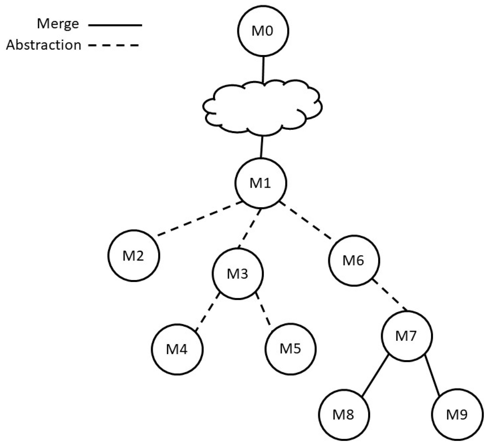
6. Interactive Process-Model Discovery through Merge and Abstraction

As discussed in Section 3, in our previous approach in [3], we provided a framework supporting the interactive and “step-by-step” discovery of the process model, based on the merge semantic operations. In this section, we extend it, providing experts, as well as the possibility of adopting the abstraction semantic operations described so far. Notably, merge and abstraction operations are orthogonal and complementary operations, working along two different dimensions: the “level of abstraction” (of the terms used to describe the process: abstraction operations) and the “level of repetition” (of equal patterns in the process model: merge operations). They can, therefore, easily be integrated within a unique model discovery procedure, supporting experts with a powerful and flexible framework to achieve the desired balance in the process model: in particular, we refer to not only the balance between overfitting and underfitting [2], but also to the balance regarding the “level of abstraction” of the terms used in the model description.
Specifically, in [3] we proposed a framework supporting process model versioning, based on a tree-of-models data structure, the versioning tree. Each node in the versioning tree corresponds to a process model. Arcs in the versioning tree correspond to merge operations. As motivated in [3], the root node of the versioning tree is the log tree.
Based on their domain knowledge, experts can analyze the current model (possibly taking advantage also of the retrieval facilities proposed in [3]; see the “analyze” option in Algorithm 5 below) and decide whether it achieves the desired balance or whether it is better to move forward to further improvements (through the application of merge operations) or even backtrack to previously built models. Given the orthogonality discussed above, such a general process can be extended by supporting, besides merge operations, also abstraction operations. The extended algorithm, called GenerateModel, is shown below (see Algorithm 5). For the sake of brevity, the options “analyze”, “merge”, and “back” are not detailed (they are expanded and widely explained in [3]).
Algorithm 5:GenerateModel pseudo-code.
1: GenerateModel (VerTree, L, KB) Output: Node
2: CurNode ← Root (VerTree)
3: Operation ← AskOp (CurNode)
4: while Operation ≠ “approve” do
5:     switch Operation do
6:       case “analyze”:
7:         … query answering operations …
8:       case “merge”:
9:         MergeParameters ← AskMergeParameters (CurNode)
10:         NewModel ← ExecuteMerge (CurNode.Model, MergeParameters)
11:         NewNode ← AppendSon (CurNode, NewModel, CurNode.AbstrST)
12:         CurNodeNewNode
13:       case “abstract”:
14:         AbstractionModality ← AskModality ()
15:         switch AbstractionModality do
16:    case “automatic_activity”:
17:     Activity ← AskActivity (KB)
18:      NewModel ← AutomaticActAbstract (KB, Activity, CurNode.Model, CurNode.AbstrST)
19:     NewAbstrSTCurNode.AbstrST ∪ {Activity}
20:    case “automatic_level”:
21:     Level ← AskLevel (KB)
22:     Activities ← GetActivities (KB, Level)
23:      NewModel ← AutomaticLevAbstract (KB, Activities, CurNode.Model, CurNode.AbstrST)
24:     NewAbstrSTCurNode.AbstrST ∪ {Activities}
25:    case “interactive_activity”:
26:     Activity ← AskAction (KB)
27:       NewModel ← InteractiveActAbstract (KB, Activity, CurNode.Model, CurNode.AbstrST)
28:     NewAbstrSTCurNode.AbstrST ∪ {Activity}
29:         case “interactive_level:
30:     Level ← AskLevel (KB)
31:     Activities ← GetActivities (KB, Level)
32:       NewModel ← InteractiveLevAbstract (KB, Level, CurNode.Model, CurNode.AbstrST)
33:     NewAbstrSTCurNode.AbstrST ∪ {Activities}
34:         end switch
35:         NewNode ← AppendSon(CurNode, NewModel, NewAbstrST)
36:         CurNodeNewNode
37:       case “back:
38:         CurNode ← AskCur (VerTree)
39:     end switch
40:     Operation ← AskOp (CurNode)
41: end while
42: return CurNode
The GenerateModel algorithm has three parameters: the versioning tree (VerTree), the log (L), and the knowledge base (KB). Before invoking the GenerateModel algorithm, the root of the versioning tree is generated, containing (i) the mined log tree and (ii) the abstraction symbol table (which is empty). The GenerateModel algorithm repeatedly proposes different operations (namely “analyze”, “merge”, “abstract”, “back”, and “approve”) to the experts, until the “approve” operation is chosen, which means that the expert accepts the model in the current node of the versioning tree as output. In short, the “analyze” operation does not change the model (and the versioning tree) and is used by the expert when s/he wants to inspect and query the model in the current node (through the facilities described in [3]). The “back” operation does not modify the versioning tree, but allows the expert to move back to a previously built node in the versioning tree. On the other hand, the “merge” operation culminates with the addition of a new node to the versioning tree, containing a new process model obtained through the application of a merge operation to the model in the current node. While the above operations were already provided in the algorithm in [3], the abstract operation deals with the extensions defined in this paper. With such an option (line 13), the analyst is asked to select among four abstraction modalities: (1) “automatic_activity”, which performs automatic abstraction of a single activity in the KB (managed at lines 16–19), (2) “automatic_level”, which performs automatic abstraction of a complete level in the KB (managed at lines 20–24), (3) “interactive_activity”, which performs interactive abstraction of a single activity (managed at lines 25–28), and (4) “interactive_level”, which performs interactive abstraction of a complete level in the KB (managed at lines 29–33). In the cases of activity-based abstractions, the GenerateModel algorithm first asks the expert which activity to abstract, then invokes an activity-based abstraction algorithm to abstract the chosen activity in the current process model (either automatically or interactively), and finally, adds the abstracted activity to the abstraction symbol table. In the cases of level-based abstractions, the GenerateModel algorithm first asks the expert which level of KB to consider for abstraction, then it invokes a level-based abstraction algorithm to abstract all the activities at the selected level of the KB (either automatically or interactively), and finally, it adds these activities to the abstraction symbol table. In both cases, the GenerateModel algorithm generates a new node in the versioning tree as a son of the current node (line 35) and sets this new node as the new current node of the versioning tree, on which subsequent operations will be performed (line 36).

7. Experimental Work

In this section, we present an experimental evaluation of our approach, considering the stroke domain. We continue our running example, considering a session of interactive process discovery, as discussed so far. During the evolution of this running example, a versioning tree expands, according to the sequence of the operations performed. For the sake of brevity, we only show the versioning tree obtained at the end of this interactive session, in Figure 16. In this versioning tree, each node corresponds to a process model. Each arc connects a process model to another model obtained after a merge or an abstraction operation. Full arcs represent merge operations, while dashed arcs identify abstractions.
In short, starting from the traces, the analyst has obtained the log tree in Figure 1, added as the node M0 in the versioning tree in Figure 16. With the application of SIM’s merge operations discussed in Section 3.4, s/he has then obtained the model in Figure 3, corresponding to the node M1 in Figure 16 (notice that, for the sake of brevity, in Figure 16, we do not make explicit the intermediate versions obtained after each merge operation: a “cloud” is inserted to graphically resume them). After that, s/he has applied the automatic abstraction operation, leading to the model in Figure 7, corresponding to the node M2 in Figure 16. The process model in Figure 7 has the merit of highlighting the main high-level procedures performed in the hospital at hand. However, as discussed in Section 5.2.1, the model is affected by a problem that makes it unacceptable (i.e., a route with three different, incompatible treatments executed in sequence). Therefore, we suppose that the analyst decides to backtrack to the model in Figure 3 and resort to the interactive abstraction facilities provided by our system. Since the direct transition to level 2 led to the problems described above, the expert decides to take control of the abstraction process, proceeding one level at a time. S/he firstly abstracts the ground model at level 3 of the KB, accepting all the abstractions proposed by the system, since there are no conflicts to resolve. The resulting model, corresponding to node M3 of the versioning tree in Figure 16, is shown in Figure 8.
This model is then used as the starting point to raise to abstraction level 2 of the KB. The abstraction algorithm analyzes the model in Figure 8 using the KB and stops to interact with the user at each identified abstraction. Most abstractions, such as r-TPA Proc, Evaluation, PH Proc, and Monitoring, only need a check by the user, as they do not create any conflict. A different situation arises in the central part of the process. Here, two abstractions generate a conflict, since TPA ia Proc can be obtained in two intersecting paths: (1) TPA ia Pre in the upper branch with TPA ia; (2) TPA ia Pre in the central branch with the same TPA ia. The intersection is shown in Figure 9a. This conflict can be resolved by abstracting only the TPA ia Proc in the central branch (Figure 9b) or only the one in the upper branch (Figure 9c).
The user selects the solution in Figure 9b, which leads to the model in Figure 10, corresponding to the node M4 of the versioning tree in Figure 16. An analysis of this model, however, reveals three problems that make it unacceptable, since none of the following are correct from the medical viewpoint: (1) all the three therapies can be performed on a single patient; this was the reason the user discarded the model in Figure 7; (2) TPA ia Pre is repeated twice for the patients passing from TPA ia Pre in the upper branch to TPA ia Proc in the middle branch, since TPA ia Proc already includes the stage of preparation; finally, (3) each patient traversing the complete upper branch is forced to receive a TPA ia Pre, without administration of the therapy. Furthermore, such a patient begins Rehab without any Monitoring. These situations are all valid reasons for discarding the model; therefore, the user backtracks to the model in Figure 8 and repeats the abstraction at level 2, choosing the alternative solution in Figure 9c.
The result of this choice (node M5 of the versioning tree in Figure 16) is shown in Figure 11. This model leads to some improvements, compared to the one in Figure 10: the problem (1) has been solved (no patient can undergo all the therapies); the problem (3) is partially solved, since the direct transition from TPA ia Proc to Rehab is no longer forced, but optional (anyway, this option is still possible). The problem (2), however, remains in this model: patients traversing from the central branch for the administration of TPA ia are forced to undergo TPA ia Pre twice (TPA ia pre is also included in TPA ia Proc). Due to these considerations, the user also discarded the model in Figure 11.
After trying all the available solutions, it was clear to the user that the model in Figure 8 was not a suitable starting point to obtain an acceptable model at level 2. The problem resided in the intersecting paths in Figure 9; therefore, intuitively, a possible solution could be to not abstract both the TPA ia Pre at level 3, but only one of them, in order to avoid conflict at level 2. With this strategy in mind, the user backtracked to the ground model in Figure 3 (node M1 of the versioning tree in Figure 16) and started the abstraction algorithm at level 3 of the KB. As before, the algorithm stopped at each detected abstraction waiting for input; the user accepted all the abstractions proposed by the system, except the TPA ia Pre in the upper branch, abstracting only the TPA ia Pre in the central branch. The obtained model is shown in Figure 12 (node M6 of the versioning tree in Figure 16).
Starting from the model in Figure 12, the user asked the system to raise to abstraction level 2, accepting all the proposed abstractions, except the abstraction of TPA ia Proc (TPA ia Pre + TPA ia) in the central branch. This model (node M7 of the versioning tree in Figure 16) is shown in Figure 13.
The model obtained with this strategy seems the most correct: it is not redundant, and it does not depict any unacceptable path, as seen before. This model also explains a clear picture of the general clinical process: after the Evaluation, the path at the top describes the treatment for patients eligible for r-TPA. In this path, the complete procedure for r-TPA (r-TPA Proc) is performed, followed by the Monitoring tests to verify the status of the patient after r-TPA administration. After the Monitoring (not detected in the previous models, and here executed at the right time), the model indicates two possible choices: rehabilitation (Rehab) or, if the thrombus did not dissolve completely, TPA ia. In the latter case, in addition to the Monitoring tests already carried out, the model states that an AngioCT must be performed before proceeding with the administration of the TPA ia. Thus, the user accepts this model as the best solution so far. Furthermore, some generalizations can be investigated, since the Monitoring activities seem to be performed at the end of each branch and merging them could simplify the process. The result of this generalization step is the model in Figure 14, corresponding to node M8 of the versioning tree in Figure 16.
The generalization step (i.e., merging all the Monitoring activities) creates a more general model, at the cost of introducing a cycle. The process model in Figure 14 suggests that a patient, after TPA ia, undergoes Monitoring, which is correct, but after that, she can cycle in a loop involving AngioCT and TPA ia again. None of the previous models presented any cycle. Thus, this model is unacceptable. After backtracking to the model in Figure 13, the user recognizes that merging all the Monitoring activities was the cause of the problem and, thus, applies the merge operation selectively, merging only the Monitoring activity at the end of the central branch and the Monitoring at the end of the lower branch. The resulting model, in Figure 15 (node M9 of the versioning tree in Figure 16), generalizes the Monitoring activity where possible, maintaining the correctness of the model in Figure 13.
The work session can then be closed, indicating the model in Figure 15 as the final solution; the versioning tree generated during this interactive session is shown in Figure 16.
In conclusion, the model in Figure 15, represented by node M9 in the versioning tree, offers the best balance between correctness and simplicity/readability. The comparison between all the models, as well as the search for the most correct/useful one, was made possible by the interactivity of the system, which, for example, allowed us to resolve conflicts in different ways, leaving the choice of the most appropriate result to the user. Moreover, the semantic KB drives the abstraction operations, allowing the user to exploit the already coded domain knowledge, select proper levels of abstraction, and perform the abstraction procedures automatically or interactively. Backtracking allows us to explore different abstraction and conflict resolution strategies.
Notably, as described in this interactive session of work, our system leaves the freedom to mix merge and abstraction operations in any order to the user.

8. Conclusions

Process traces are a strategic source of information, which can be exploited to support different tasks, including the discovery of the underlying process model. Our work follows one of the main streams of research in process mining, as pointed out in [41], proposing the articulation of the discovery procedure into steps and involving the analysts in the discovery procedure itself [2]. Following such a general guideline, in our previous paper [3], we proposed an SIM (semantic interactive miner), an innovative process mining approach supporting the possibility of involving analysts in the step-by-step selection of generalization operations, in order to merge parts of the model to achieve compactness and reduce redundancy.
In this paper, we have substantially extended such an approach, to consider a closely related issue. In many medical domains, large bodies of knowledge are available and encoded a priori. In particular, in several cases, such knowledge consists of (or contains) a taxonomic description of the activities to be executed, considering the refinement (ISA) and partonomic (part-of) relationships between them. In these contexts, it seems to us a real “waste” of resources not to exploit such available knowledge in process discovery. Indeed, since the discovered process models can be very complex and difficult to interpret (i.e., “spaghetti-like” [1]), ISA and part-of knowledge can be precious for obtaining more abstract, compact, and easy-to-read models, in which unnecessary details are removed by moving to a higher level (in terms of the hierarchy provided by the pre-encoded knowledge base). The development of an approach exploiting available ISA and part-of knowledge in process model discovery, implemented and fully integrated into the open-source process mining framework ProM, is the main innovative contribution of this paper.
Notably, the knowledge-based abstraction operations introduced in this paper are orthogonal (and complementary) to the merge ones we previously defined in [3]: merge operations generalize the process model by “putting together” recurrent patterns, but maintain the same level of detail in the description of the activities, while abstraction operations move to a higher hierarchical level. Given such an orthogonality, we have been able to integrate the new knowledge-based abstraction facilities in SIM through a modular approach, described in Section 6. The running example shows how such modularity facilitates the analyst in the discovery of a compact and easy-to-interpret process model.
A fair comparison with other process mining algorithms is not possible, since existing approaches do not exploit semantic knowledge for interactive model abstraction. Nevertheless, in Appendix A, we propose an experimental comparison with four well-known mining algorithms embedded in ProM, based both on the calculation of some quantitative indicators and on a qualitative visual examination of the obtained models. The comparison shows the advantages of SIM, from the point of view of simplicity and readability.
Additional quantitative indicators could be considered, as well.
Indeed, in [3], we calculated a set of quantitative parameters, such as precision and replay fitness [4], for every model generated during the interactive session of work with the expert. This information was provided to the expert to support her/his evaluation of the current model, until s/he approved it as the final output of the process mining work. We believe that quantitative parameters would be helpful for evaluating the output of the interactive abstraction work: all nodes in the versioning tree should be filled with details about the precision and replay fitness of the model they represent. However, extending the literature algorithms [4] to calculate quantitative parameters, in our context, is a complex research task. Indeed, the existing algorithms typically operate by replaying ground traces on the mined model and cannot be easily adapted to a situation where the model may contain nodes that represent activities expressed at different levels of abstraction. In the future, we will investigate how to properly and efficiently modify the algorithms at hand, in order to deal with this important extension. Such an evaluation method could also be exploited to compare (in terms of precision and replay fitness) the process models discovered without abstraction (e.g., mined through our previous version of SIM or other tools) with the models obtained through the automatic application of level-based abstraction. Additionally, an interesting future research activity could study, in domains in which the hierarchical knowledge is not already consolidated, the sensitivity of the results obtained through activity-based or level-based automatic abstraction to the quality of the hierarchical knowledge.
Moreover, we will extensively test our approach in different medical domains, including COVID-19 patient management.

Author Contributions

Writing—original draft, A.B., M.G., G.L., S.M., M.S. and P.T. All authors have read and agreed to the published version of the manuscript.

Funding

This research has the financial support of the Università del Piemonte Orientale.

Data Availability Statement

Not Applicable, the study does not report any data.

Conflicts of Interest

The authors declare no conflict of interest.

Appendix A. Experimental Comparison

In this section, we present an experimental evaluation to show the effectiveness of our interactive abstraction algorithm in generating a more compact/simple process model, concerning the existing state-of-the-art mining algorithms.
To this end, we used the ProM 6.10 tool to mine the process models, starting from the same real-world log we used for generating the log tree of Figure 1, and we compared the obtained process models with the one obtained with our interactive abstraction algorithm, shown in Figure 15, using two quantitative metrics, namely the number of nodes and the number of edges in the process model.
Specifically, we considered the following plugins of ProM (that we used with their default parameters): the “Alpha Miner” plugin (hereafter, “Alpha”), the “Mine for a Fuzzy Model” plugin (hereafter, “Fuzzy”), the “Mine for a Heuristic Net for Heuristic Miner” plugin (hereafter, “Heuristic”), and the “Mine for a Petri Net using ILP” plugin (hereafter, “ILP”). Figure A1, Figure A2, Figure A3 and Figure A4 show the process models generated by the above plugins.
Figure A1. Process model generated by the Alpha plugin. The place indicated as “1”, followed by the action “#” represents the starting place and action of the model, while the “E” followed by “$” represents the ending (final) state and the final action of the model.
Futureinternet 14 00357 g0a1
Figure A2. Process model generated by the Fuzzy plugin. The box containing the symbol “#” indicates the entry point of the model, while the “$” box represents the ending (final) action of the model.
Futureinternet 14 00357 g0a2
Figure A3. Process model generated by the Heuristic plugin. The box containing the symbol “#” indicates the entry point of the model, while the “$” box represents the ending (final) action of the model.
Futureinternet 14 00357 g0a3
Figure A4. Process model generated by the ILP plugin. The place indicated as “1” represents the starting place, while the “E” represents the ending (final) state of the model.
Futureinternet 14 00357 g0a4
In Table A1, we report the values of the two metrics obtained from the above process models and from the one shown in Figure 15, which we denoted as SIM. Note that such metrics have been computed according to the formalism used by each ProM plugin to represent a process model and the different formalisms that may lead to slightly different results. From the table, we can observe that SIM, with respect to the other mining algorithms, can generate a process model with the smallest number of nodes and edges, and thus, one which is more compact and easier to read by domain experts. It is worth noting that the smaller number of nodes in the SIM model does not mean that some activities are not modeled in the process; instead, it means that these activities have been replaced with (i.e., abstracted by) other ones. Moreover, the fewer number of edges is obtained thanks to the fewer number of nodes and also to the ability of SIM to avoid introducing loops or other relations that were not present in the original log.
A qualitative analysis of the models above reveals the additional aspects and problems to be reported. In the following, we will analyze the most notable issues.
The model obtained by the alpha miner (Figure A1) has a number of nodes that are only marginally higher than the SIM model, but the presence of many edges between the nodes/transitions/activities involved, and the constraints introduced by the syntax of Petri nets (a transition/activity is activated only when all the incoming places contain a token) make it extremely difficult to identify the therapeutic paths. While the understanding of the initial phases (CT and BT, executed in parallel, with their output places enabling Eval) is straightforward, the identification of other paths is not. For example, if we aim to understand the contexts where the activity ASA is performed, we need to identify and list all the execution steps able to put a token in all the four ASA input places to activate it. Starting with the first activity #, an AND split generates two tokens, activating both CT and BT. When enabled, BT fires a token in a place, which is input to Eval, while CT fires two tokens: one as input to Eval, and one as input to ASA. Eval is then activated, firing four tokens in its AND split output. Two of them end up as input to ASA, and one can activate (XOR) ASA or MR DW. In the first case, all the above steps generate the simple Eval—ASA sequence; in the second case, it is necessary to study what happens after the activation of MR DW. Here, MR DW fires a token in a place which, together with the other input place, already containing a token previously fired by Eval, activates the ECG activity. The latter fires a token that activates MR, which, in turn, generates two tokens that, in combination with the previously fired ones, activate ASA. Following these steps, we can conclude that ASA can be executed in a second context, described by the Eval–MR DW–ECG–MR–ASA sequence. This level of complication, and the need to simulate all the possible execution steps to retrieve the treatment paths, requires the central role of an expert analyst, since a physician would not be able to read and identify the procedures hidden in the model in Figure A1. A process model such as the one in Figure 15, on the other hand, makes the interpretation task a much easier operation. Furthermore, the model in Figure A1 shows that this miner, with the default settings, is not able to integrate the r-TPA activity in any execution context, thus avoiding the user’s obtaining information about the therapeutic steps to be performed while administering this life-saving treatment.
Table A1. Quantitative comparison of process models.
Process ModelNumber of NodesNumber of Edges
Alpha1450
Fuzzy1422
Heuristic1422
ILP1442
SIM1114
The model produced by the fuzzy miner (Figure A2) is much more intuitive and easier to read than the above one (Figure A1). However, it presents some activities that cycle on themselves and some cyclical paths that are difficult to explain from a medical point of view. For example, a cycle between ECG and r-TPA can be seen in the lower right part of the model, suggesting that this therapy can be administered multiple times to the same patient. The same happens in the ASA–AngioCT–TPA ia–ECG–MR–ASA cycle. Thrombolysis therapies are administered to the patient only once, given their severe counter-indications, such as the risk of hemorrhagic episodes. Administering a single TPA ia is allowed after an ineffective r-TPA, but repeating the same TPA treatment is not allowed.
The model generated by the heuristic miner (Figure A3) has strengths and weaknesses that are similar to that of the model illustrated above (Figure A2). The model is simple to read and interpret. However, even in this case, there are cycles that are not allowed, from the medical point of view, such as ECG–r-TPA–ECG. In addition, arcs allow some therapeutic paths to return to the ECG activity, potentially re-starting the same therapy several times. As a final remark, path #–CT–ASA suggests that some therapies should be started before the patient has been evaluated by a neurologist (Eval).
The ILP model (Figure A4) shares the difficulties of interpretation that have already been seen in the process generated by the alpha miner (Figure A1). Additionally, in this case, the analyst must simulate the evolution of the tokens across the model, in order to extract the therapeutic paths hidden in the complexity of the high number of edges. Furthermore, the model describes situations that are not acceptable from the medical point of view. For example, after the start activity (#), an AND split generates two outgoing tokens. Among these, one activates the BT activity, while the other one activates a single activity (XOR split), chosen from CT, r-TPA, and MR. This means that a patient can undergo an r-TPA without neurological evaluation (Eval) and with no preliminary evaluation tests or preparation activities. Problems also arise from the structural point of view, since the model is not sound. For example, after executing the activity start (#) and the AND split that follows, the token activating BT can continue to travel inside the paths described by the model. At the same time, the second token can cross the path r-TPA → ASA → Rehab → $ to enter the final place (E), ending the treatment process for the given patient. Unfortunately, the other token, initially split for the same patient, could still circulate in the model after the treatment has been terminated. Furthermore, some activities, e.g., Eval, split their output into two places with an AND split, but one of these places can trigger the same activity again (e.g., Eval), thus forming a loop. Each time the loop is repeated, however, the Eval activity splits the input token into two outgoing tokens, creating multiple split copies, taking different directions and paths. Potentially, the model could fill up with split tokens, crossing the model in independent directions without the chance to eventually join before one of them reaches the end place, terminating the process.
In conclusion, the model generated by SIM offers the advantage of greater simplicity, interpretability, and easier identification of the therapeutic paths, compared to most traditional miners available on ProM.

References

  1. Van der Aalst, W.M.P. Data Mining. In Process Mining: Data Science in Action; Springer: Berlin/Heidelberg, Germany, 2016; pp. 89–121. [Google Scholar] [CrossRef]
  2. Van der Aalst, W.M.P.; Rubin, V.; Verbeek, H.M.W.; van Dongen, B.F.; Kindler, E.; Günther, C.W. Process mining: A two-step approach to balance between underfitting and overfitting. Softw. Syst. Modeling 2010, 9, 87. [Google Scholar] [CrossRef] [Green Version]
  3. Bottrighi, A.; Canensi, L.; Leonardi, G.; Montani, S.; Terenziani, P. Interactive mining and retrieval from process traces. Expert Syst. Appl. 2018, 110, 62–79. [Google Scholar] [CrossRef]
  4. Buijs, J.; van Dongen, B.; van der Aalst, W.M.P. On the role of fitness, precision, generalization and simplicity in process discovery. In Proceedings of the On the Move to Meaningful Internet Systems: OTM 2012, Rome, Italy, 10–14 September 2012; Springer: Berlin/Heidelberg, Germany, 2012; pp. 305–322. [Google Scholar] [CrossRef]
  5. Leemans, S.J.J.; Fahland, D.; van der Aalst, W.M.P. Scalable Process Discovery and Conformance Checking. Softw. Syst. Model. 2018, 17, 599–631. [Google Scholar] [CrossRef] [Green Version]
  6. Weijters, A.; van der Aalst, W.M.P.; de Medeiros, A.A. Process Mining with the Heuristic Miner Algorithm, WP166; Eindhoven University of Technology: Eindhoven, The Netherlands, 2006. [Google Scholar]
  7. Grando, M.A.; Schonenberg, M.H.; van der Aalst, W.M.P. Semantic Process Mining for the Verification of Medical Recommendations. In HEALTHINF 2011—Proceedings of the International Conference on Health Informatics, Rome, Italy, 26–29 January 2011; Traver, V., Fred, A.L.N., Filipe, J., Gamboa, H., Eds.; SciTePress: Setúbal, Portugal, 2011; pp. 5–16. [Google Scholar]
  8. Pedrinaci, C.; Domingue, J.; Brelage, C.; van Lessen, T.; Karastoyanova, D.; Leymann, F. Semantic Business Process Management: Scaling Up the Management of Business Processes. In Proceedings of the 2nd IEEE International Conference on Semantic Computing (ICSC 2008), Santa Clara, CA, USA, 4–7 August 2008; IEEE Computer Society: Washington, DC, USA, 2008; pp. 546–553. [Google Scholar] [CrossRef] [Green Version]
  9. Smirnov, S.; Reijers, H.A.; Weske, M. From fine-grained to abstract process models: A semantic approach. Inf. Syst. 2012, 37, 784–797. [Google Scholar] [CrossRef]
  10. Bose, R.P.J.C.; van der Aalst, W.M.P. Abstractions in Process Mining: A Taxonomy of Patterns. In Proceedings of the Business Process Management, 7th International Conference, BPM 2009, Ulm, Germany, 8–10 September 2009; Lecture Notes in Computer Science. Dayal, U., Eder, J., Koehler, J., Reijers, H.A., Eds.; Springer: Berlin/Heidelberg, Germany, 2009; pp. 159–175. [Google Scholar] [CrossRef]
  11. Haigh, K.Z.; Yaman, F. RECYCLE: Learning looping workflows from annotated traces. ACM TIST 2011, 2, 42. [Google Scholar] [CrossRef]
  12. Mendling, J.; Verbeek, H.M.W.; Dongen, B.F.; van der Aalst, W.M.P.; Neumann, G. Detection and prediction of errors in EPCs of the SAP reference model. Data Knowl. Eng. 2008, 64, 312–329. [Google Scholar] [CrossRef]
  13. Sadiq, S.; Marjanovic, O.; Orlowska, M. Managing change and time in dynamic workflow processes. Int. J. Coop. Inf. Syst. IJCIS 2000, 9, 93–116. [Google Scholar] [CrossRef] [Green Version]
  14. Vanhatalo, J.; Völzer, H.; Koehler, J. The Refined Process Structure Tree. In Business Process Management; Dumas, M., Reichert, M., Shan, M.-C., Eds.; Springer: Berlin/Heidelberg, Germany, 2008; pp. 100–115. [Google Scholar] [CrossRef]
  15. Polyvyanyy, A.; Smirnov, S.; Weske, M. The Triconnected Abstraction of Process Models. In Proceedings of the Business Process Management, 7th International Conference, BPM 2009, Ulm, Germany, 8–10 September 2009; Lecture Notes in Computer, Science. Dayal, U., Eder, J., Koehler, J., Reijers, H.A., Eds.; Springer: Berlin/Heidelberg, Germany, 2009; pp. 229–244. [Google Scholar] [CrossRef] [Green Version]
  16. Baier, T.; Rogge-Solti, A.; Mendling, J.; Weske, M. Matching of Events and Activities: An Approach Based on Behavioral Constraint Satisfaction. In Proceedings of the 30th Annual ACM Symposium on Applied Computing, SAC ’15, Salamanca, Spain, 13–17 April 2015; Association for Computing Machinery: New York, NY, USA, 2015; pp. 1225–1230. [Google Scholar] [CrossRef] [Green Version]
  17. Fazzinga, B.; Flesca, S.; Furfaro, F.; Masciari, E.; Pontieri, L. A Probabilistic Unified Framework for Event Abstraction and Process Detection from Log Data. In Proceedings of the on the Move to Meaningful Internet Systems: OTM 2015 Conferences—Confederated International Conferences: CoopIS, ODBASE, and C&TC 2015, Rhodes, Greece, 26–30 October 2015; pp. 320–328. [Google Scholar] [CrossRef]
  18. Ferreira, D.R.; Szimanski, F.; Ralha, C.G. Improving process models by mining mappings of low-level events to high-level activities. J. Intell. Inf. Syst. 2014, 43, 379–407. [Google Scholar] [CrossRef]
  19. Leemans, S.J.J.; Goel, K.; van Zelst, S.J. Using Multi-Level Information in Hierarchical Process Mining: Balancing Behavioural Quality and Model Complexity. In Proceedings of the 2nd International Conference on Process Mining, ICPM 2020, Padua, Italy, 4–9 October 2020; Dongen, B.F., van Montali, M., Wynn, M.T., Eds.; IEEE: Piscataway, NJ, USA; pp. 137–144. [Google Scholar] [CrossRef]
  20. Leonardi, G.; Striani, M.; Quaglini, S.; Cavallini, A.; Montani, S. Leveraging semantic labels for multi-level abstraction in medical process mining and trace comparison. J. Biomed. Inform. 2018, 83, 10–24. [Google Scholar] [CrossRef] [PubMed]
  21. De Leoni, M.; Dundar, S. From Low-Level Events to Activities—A Session-Based Approach (Extended Version). arXiv 2019, arXiv:1903.03993. [Google Scholar]
  22. Tax, N.; Sidorova, N.; Haakma, R.; van der Aalst, W.M.P. Event Abstraction for Process Mining using Supervised Learning Techniques. arXiv 2016, arXiv:1606.07283. [Google Scholar]
  23. Van Zelst, S.J.; Mannhardt, F.; de Leoni, M.; Koschmider, A. Event abstraction in process mining: Literature review and taxonomy. Granul. Comput. 2020, 6, 719–736. [Google Scholar] [CrossRef]
  24. Gaily, F.; Alkhaldi, N.; Casteleyn, S.; Verbeke, W. Recommendation-Based Conceptual Modeling and Ontology Evolution Framework (CMOE+). Bus. Inf. Syst. Eng. 2017, 59, 235–250. [Google Scholar] [CrossRef]
  25. Guizzardi, G.; Figueiredo, G.; Hedblom, M.; Poels, G. Ontology-Based Model Abstraction. In Proceedings of the 13th International Conference on Research Challenges in Information Science (RCIS), Brussels, Belgium, 29–31 May 2019; pp. 1–13. [Google Scholar] [CrossRef] [Green Version]
  26. Dixit, P.M.; Verbeek, H.M.W.; Buijs, J.C.A.M.; van der Aalst, W.M.P. Interactive Data-Driven Process Model Construction. In Proceedings of the Conceptual Modeling—37th International Conference, ER 2018, Xi’an, China, 22–25 October 2018; Lecture Notes in Computer Science. Trujillo, J., Davis, K.C., Du, X., Li, Z., Ling, T.W., Li, G., Lee, M.-L., Eds.; Springer: Berlin/Heidelberg, Germany, 2018; pp. 251–265. [Google Scholar] [CrossRef]
  27. Greco, G.; Guzzo, A.; Lupia, F.; Pontieri, L. Process Discovery under Precedence Constraints. ACM Trans. Knowl. Discov. Data 2015, 9, 32. [Google Scholar] [CrossRef]
  28. Rembert, A.J.; Omokpo, A.; Mazzoleni, P.; Goodwin, R. Process Discovery Using Prior Knowledge. In Proceedings of the Service-Oriented Computing 11th International Conference, ICSOC 2013, Berlin, Germany, 2–5 December 2013; Lecture Notes in Computer, Science. Basu, S., Pautasso, C., Zhang, L., Fu, X., Eds.; Springer: Berlin/Heidelberg, Germany, 2013; pp. 328–342. [Google Scholar] [CrossRef]
  29. Maggi, F.M.; Bose, R.P.J.C.; van der Aalst, W.M.P. A Knowledge-Based Integrated Approach for Dis-covering and Repairing Declare Maps. In Proceedings of the Advanced Information Systems Engineering—25th International Conference, CAiSE 2013, Valencia, Spain, 17–21 June 2013; Lecture Notes in Computer Science. Salinesi, C., Norrie, M.C., Pastor, O., Eds.; Springer: Berlin/Heidelberg, Germany, 2013; pp. 433–448. [Google Scholar] [CrossRef]
  30. Schuster, D.; van Zelst, S.J.; van der Aalst, W.M.P. Cortado—An Interactive Tool for Data-Driven Process Discovery and Modeling. In Proceedings of the Application and Theory of Petri Nets and Concurrency—42nd International Conference, PETRI NETS 2021, Virtual Event, 23–25 June 2021; Lecture Notes in Computer, Science. Buchs, D., Carmona, J., Eds.; Springer: Berlin/Heidelberg, Germany, 2021; pp. 465–475. [Google Scholar] [CrossRef]
  31. Benevento, E.; Dixit, P.M.; Sani, M.F.; Aloini, D.; van der Aalst, W.M.P. Evaluating the Effectiveness of Interactive Process Discovery in Healthcare: A Case Study. In Business Process Management Workshops—BPM 2019 International Workshops, Vienna, Austria, 1–6 September 2019; Revised Selected Papers, Lecture Notes in Business Information Processing; Di Francescomarino, C., Dijkman, R.M., Zdun, U., Eds.; Springer: Berlin/Heidelberg, Germany; pp. 508–519. [CrossRef]
  32. Valero-Ramon, Z.; Fernández-Llatas, C.; Valdivieso, B.; Traver, V. Dynamic Models Supporting Personalised Chronic Disease Management through Healthcare Sensors with Interactive Process Mining. Sensors 2020, 20, 5330. [Google Scholar] [CrossRef] [PubMed]
  33. Mans, R.; van der Aalst, W.M.P.; Vanwersch, R.; Moleman, A. Process Mining in Healthcare: Data Challenges When Answering Frequently Posed Questions. In ProHealth/KR4HC; Lecture Notes in Computer Science; Lenz, R., Miksch, S., Peleg, M., Reichert, M., Riaño, D., ten Teije, A., Eds.; Springer: Berlin/Heidelberg, Germany, 2013; pp. 140–153. [Google Scholar] [CrossRef]
  34. Mans, R.; Schonenberg, H.; Leonardi, G.; Panzarasa, S.; Cavallini, A.; Quaglini, S.; van der Aalst, W.M.P. Process Mining Techniques: An Application to Stroke Care. In Proceedings of MIE, Studies in Health Technology and Informatics; Andersen, S., Klein, G.O., Schulz, S., Aarts, J., Eds.; IOS Press: Amsterdam, The Netherlands, 2008; pp. 573–578. [Google Scholar] [CrossRef]
  35. Mans, R.; Schonenberg, H.; Song, M.; van der Aalst, W.M.P.; Bakker, P. Application of process mining in healthcare—A case study in a Dutch hospital. In Biomedical Engineering Systems and Technologies, Communications in Computer and Information Science; Fred, A., Filipe, J., Gamboa, H., Eds.; Springer: Berlin/Heidelberg, Germany, 2009; pp. 425–438. [Google Scholar] [CrossRef]
  36. Perimal-Lewis, L.; Qin, S.; Thompson, C.; Hakendorf, P. Gaining Insight from Patient Journey Data using a Process-Oriented Analysis Approach. In Proceedings Workshop on Health Informatics and Knowledge Management (HIKM); Conferences in Research and Practice in Information Technology; Butler-Henderson, K., Gray, K., Eds.; Australian Computer Society: Sydney, Australia, 2012; pp. 59–66. [Google Scholar]
  37. Rojas, E.; Munoz-Gama, J.; Sepulveda, M.; Capurro, D. Process mining in healthcare: A literature review. J. Biomed. Inform. 2016, 61, 224–236. [Google Scholar] [CrossRef]
  38. International Health Terminology Standards Development Organisation. SNOMED Clinical Terms. 2015. Available online: http://www.ihtsdo.org/snomed-ct (accessed on 24 October 2022).
  39. Nahler, G. Anatomical therapeutic chemical classification system (ATC). In Dictionary of Pharmaceutical Medicine; Springer: Vienna, Austria, 2009; p. 8. [Google Scholar] [CrossRef]
  40. McGuinness, D.L.; van Harmelen, F. OWL Web Ontology Language. 2004. Available online: http://www.w3.org/TR/owl-features/ (accessed on 24 October 2022).
  41. Thompson, K. Programming Techniques: Regular Expression Search Algorithm. Commun. ACM 1968, 11, 419–422. [Google Scholar] [CrossRef]
Figure 1. The starting process model (log tree) of our running example.
Futureinternet 14 00357 g001
Figure 2. The results of the example search.
Futureinternet 14 00357 g002
Figure 3. Process model after the merge operations.
Futureinternet 14 00357 g003
Figure 4. The KB describing the main stroke management procedures in acute phase.
Futureinternet 14 00357 g004
Figure 5. (A) Example of a graph with intersecting paths, where the red box marks the path p = <A1 → A2 → … →Ak>, which will be substituted with a single node A, as illustrated in (B), where the resulting model shown the re-addressing of all the arcs entering/exiting any node in P as arcs entering/exiting A and preserving the “relevant” intersecting path … I2 → A2 → O1.
Futureinternet 14 00357 g005
Figure 6. (A) Conflict resolution example in a graph with three occurrences of the path {A1 → A2 → A3}, highlighted with a blue box for each occurrence. (B) Selected abstraction on the occurrences of the paths, highlighted with a red box for each selected occurrence. (C) Resulting model.
Futureinternet 14 00357 g006
Figure 7. Process model abstracted at level 2 through the fully automatic algorithm.
Futureinternet 14 00357 g007
Figure 8. Process model interactively abstracted at level 3.
Futureinternet 14 00357 g008
Figure 9. Conflict situation, with red boxes indicating the two conflicting abstractions (a) and possible solutions (b,c).
Futureinternet 14 00357 g009
Figure 10. Process model abstracted at level 2 through the solution in Figure 11b.
Futureinternet 14 00357 g010
Figure 11. Process model abstracted at level 2 through the solution in Figure 9c.
Futureinternet 14 00357 g011
Figure 12. Process model interactively abstracted at level 3 with a different strategy.
Futureinternet 14 00357 g012
Figure 13. Process model interactively abstracted at level 3 with a different strategy.
Futureinternet 14 00357 g013
Figure 14. Process model in Figure 13 resulting from merging the Monitoring activities.
Futureinternet 14 00357 g014
Figure 15. Process model in Figure 13 resulting from the selective merging of Monitoring.
Futureinternet 14 00357 g015
Figure 16. Versioning tree of the interactive session of work. For the sake of brevity and clarity, we represent as a cloud the sequence of nodes resulting from the application of the set of merging operations, as discussed in Section 3.4.
Futureinternet 14 00357 g016
Publisher’s Note: MDPI stays neutral with regard to jurisdictional claims in published maps and institutional affiliations.

