1. Introduction
The security of networks has become a major challenge in recent years. First, there is a need to keep information confidential, so that only authorized parties have access to it, and protect the information transmitted over the network [
1], which can even cover the backup of files or passwords stored on computers that are connected online, as well as access to computer systems and applications. This problem may be solved by requiring users to utilize keys to access their workstations, password secure critical documents, and digitally sign their emails [
1]. The second safety challenge involves the protection of the internet infrastructure. The purposes are to protect against attacks on the configuration of network devices, stealing networking resources and, consequently, maliciously jamming nodes or connections with disingenuous data that prevent legitimate messages from passing [
1].
One solution is visible light communication, a new emerging paradigm of wireless technology proposed in the beginning of 2000s [
2]. This technology was designed as a point-to-point wireless communication link between an LED light and a receiver, equipped with a photo detection (PD) system. The transfer of rate depends on the digital technology used and, thus, on the light [
3]. According to [
4], the light communication system (LCS) incorporating white LED illumination has received considerable attention in the last decade. In the paper, the authors propose a handover algorithm for an internal cellular system to extend the bandwidth transmission. There are several studies on security, in many aspects, namely the physical layer, MAC layer, indoor communication, outdoor communication, inter-channel interference, etc. In [
5], the paper identifies the physical characteristics of VLC systems with security relevance. It also summarizes all of the security techniques that have been proposed in the literature for VLCs to date, including the physical layer security (PLS), which is discussed from an information theoretic perspective, as well as availability and integrity issues. The paper also addresses issues of secure localization and key generation [
5].
Other articles have proposed solutions based on OFDM modulation, and how to exploit this modulation for the benefit of cryptography and noise during communications in the system [
6]. In [
6], the authors provide an overview of recent developments in Li-Fi physical layer security (PLS) and explains the main differences between Li-Fi PLS and RF PLS. Furthermore, the authors of [
7] present a new key extraction procedure for orthogonal frequency division multiplexing (OFDM) schemes in an indoor setting. The methodology presented extracts keys at the media access control (MAC) and physical levels. Because each OFDM signal frame is encrypted with a distinct key, it provides excellent physical security. The authors of [
8] also propose a Li-Fi access point (AP) structure that employs orthogonal frequency division multiplexing (OFDM) and a tunable optical coding/decoding technique based on the optical pulse delay in an optical delay line (ODL) loop vector to allow efficient mapping of OFDM-based data access and transfer. In this paper, we present a generalized BM method for protecting and making our network more secure, especially during this global health crisis. In terms of complexity, our improved method has a complexity of O(L
) for both encoding and decoding. Another advantage of this approach is that even if the intruder discovers the encryption algorithm, the intruder will be unable to decode a message since he/she needs the value of k to encode and decode it. According to our estimations, even if the approach changes, the error-correcting aspect will not alter.
3. Application and Overview
The Reed–Solomon error correcting codes that employ the Berlekamp–Massey method were referenced by the author of [
9]. We are particularly interested in the Berlekamp–Massey approach, and based on the publication of [
9], we proposed an improved BM solution that can both encrypt a message and correct transmission issues during the network connection.
Reed–Solomon (RS) error correcting codes operate on a dataset that is represented as a set of finite field elements known as symbols. Multiple symbol problems can be identified and resolved using RS codes. Denoted by RS (N,K), where N is the number of bits in the code word and K is the number of bits in the information word. We specify two variables m that determine the length of the symbols and t that limit the maximum number of symbols, which may be rectified for each pair RS (N,K) [
10].
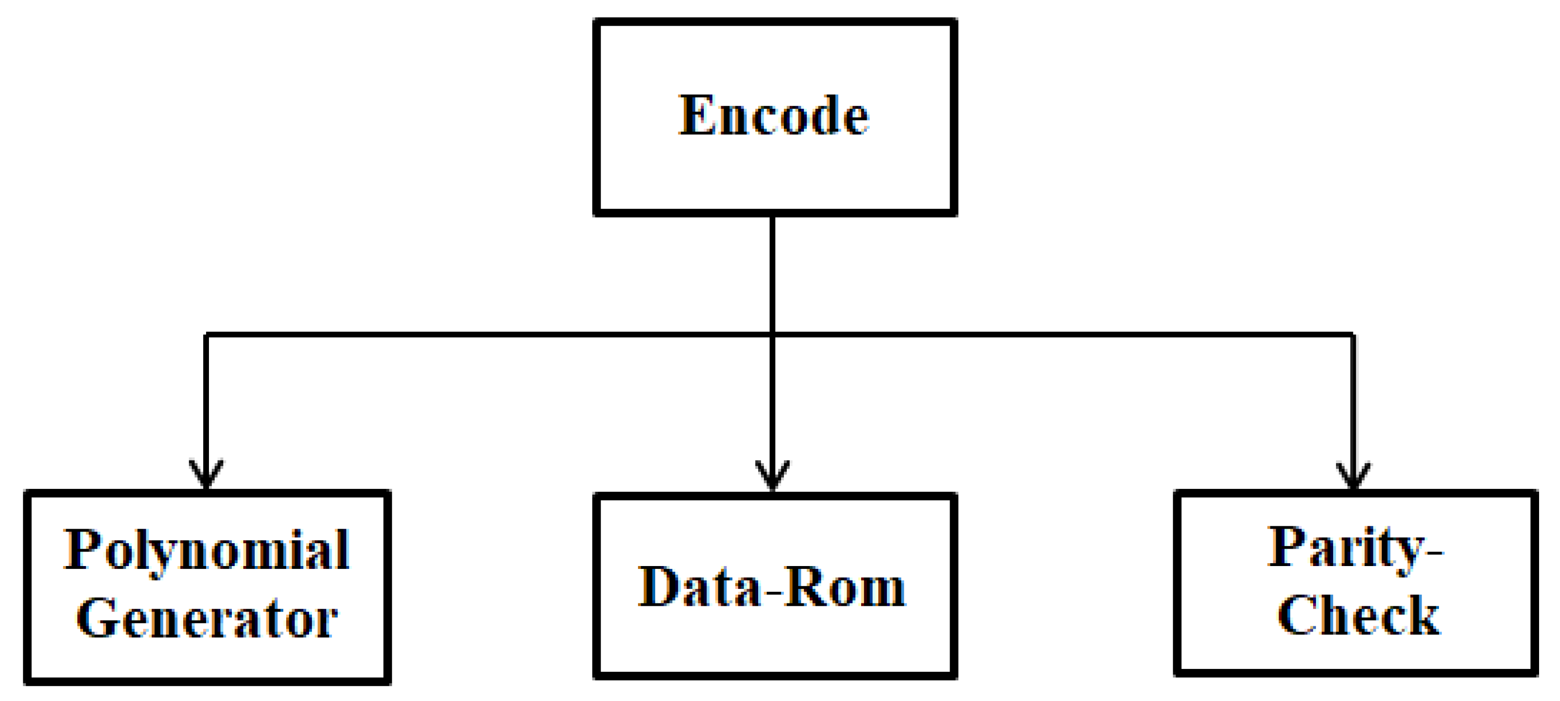
The encoder architecture shows that each number is associated with a degree input, which is a constant of the polynomial g(x). For a given unit, the polynomial information i(x) is specified component-by-component in the encoder [
11]. These components check at the encoder issue once desired latitude is reached, where the management logic returns them via an associated degree adder to provide the appropriate parity. This process continues until all k symbols (elements) of i(x) have been input to the encoder [
11]. At this point, the output control logic only allows the path of the input file, while the equality path remains disabled. With an output latitude of about one clock cycle, the encoder issues the last data frame with the (k + 1)th clock [
12]. In addition, the feedback control logic feeds the output of the adder into the bus during the first k clock cycles. A period of at least n − k timing of the clock after the entry of the last frame in the encoder, i.e., at the kth timing of the clock [
12]. Meanwhile, the feed-forward controller disables the adder output so that there is no feed-forward and continuously supplies zero symbols to the bus. Similarly, the output logic command disables the input information path and allows the encoder to output equality symbols (from the k + 2th to the n + 1th timing of the clock). Thus, a new unit starts at the n + 1th timing of the clock. The basic idea of the Reed–Solomon decoder is to detect an erroneous sequence with few terms, which, summed to the received data, results in a valid code word. Several steps are necessary for the decoding of these codes [
11];
Figure 4. Because of the small number of symbols that Reed–Solomon coding can correct, this coding is very poor, with an impulsive noise of long duration, or regular random noise. The linear complexity of the encoding of RS codes is O(nlogn) and O(nlog
2n), which pushed us to propose another algorithm of error correction while keeping the concept of RS codes in
Figure 5 [
12].
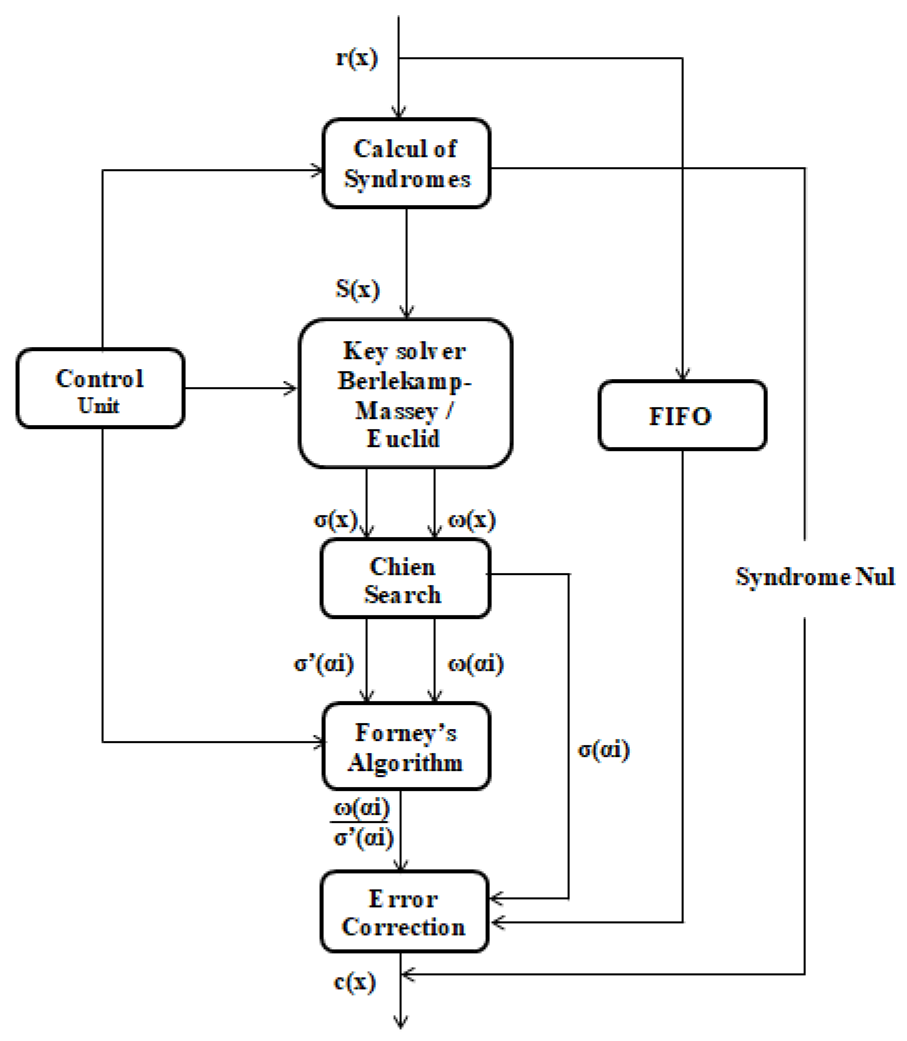
The RS code decoding steps are summarized in the diagram of
Figure 4; the identification of the variables is clarified in
Table 1.
The code word r(x) = c(x) + e(x) [
11]. RS decoder can detect the position and length of up to t errors (or 2t deletions) and correct them [
10].
Steps to decode RS Code [
11]:
(1) Determine the syndrome generator;
(2) Use Berlekamp’s algorithm or Euclid’s algorithm to form the polynomial error;
(3) Find the roots of this polynomial; usually this is done using the Chein search algorithm;
(4) Determine the error type, Forney’s algorithm, or any other matrix inversion algorithm calculates this;
(5) Correct the faulty symbols by overlaying the mask and the data word, and inverting all the bits that are corrupted one-by-one using the XOR operation [
11].
4. Results and Discussion
The idea is to review the Berlekamp–Massey, and at the end modify the result and adapt an error correction to the transmitted message. Let us take the message to be sent m = 110,111,000 with a length of 9 bits, we will unroll the modified Berlekamp–Massey; results are presented in
Table 2. From
Table 2, N is the number of bits in the sent sequence,
denotes the number of bits in the sent message, L represents the number of errors, and M denotes the size of the LFSR produced by Berlekamp–Massey. We will consider d, the key created by our method. Each sent message creates a secret key, and f(x) and g(x) are the error locator polynomials, which determine the erroneous symbols that occur during message transmission, and the error estimator polynomial, which corrects the symbols that contain errors, respectively.
To encode our previous message (m), we apply an XOR between m and the key obtained by the BM algorithm that we modified; this key will be on 3 bits, for the digits obtained, different from “0” and “1”. The encrypted message is d(x). Now, to decode d(x), we reapply an XOR between it and k in binary. The decoded message d(x), then with errors, to correct these errors, we will go through (02) steps:
step: we apply an XOR between the initial message (m) and the key this time on 4 bits for the digits different from 0 and 1, we will call the result obtained p(x).
step: an XOR will be applied between the d’(x) and p(x).
Demonstration:
Encode: m ⊕ key (3 bits): [1 1 0 1 1 1 0 0 0] ⊕ [1 0 1 0 1 0 1 0 0] = [0 1 1 1 0 1 1 0 0]: d(x).
Decode: d(x) ⊕ k (9 for this example): [0 1 1 1 0 1 1 0 0] ⊕ [1 0 0 1 0 0 0 0 0] = [1 1 1 0 0 1 1 0 0]: d’(x).
Correction errors:
step: m ⊕ key (4 bits) = [1 1 0 1 1 1 0 0 0] ⊕ [1 0 0 1 0 1 0 0 1] = [0 1 0 0 1 0 0 0 1]: p(x).
step: d’(x) ⊕ p(x) = [1 1 1 0 0 1 1 0 0] ⊕ [0 1 0 0 1 0 0 0 1] = [1 1 0 1 1 1 0 0 0].
The rule
ensures that the Berlekamp–Massey algorithm runs correctly. The rule is assured for the results in
Table 2.
Berlekamp–Massey is a variant to the Reed–Solomon corrective codes, which consist, on the one hand, in constructing for successive values of N, an LFSR of length LN, and feedback polynomial f
, which generates the first N bits of the sequences [
12]. The sequences sent (encoded) must be a multiple of a polynomial S(x), called the generator polynomial, known in advance to the sender and the receiver. We can show that, for N = 2L, the algorithm returns the feedback polynomial of the starting LFSR. On the other hand, to generate a key from the sent message, which will be of the same size of it, each message will have its own key; we cannot have two different messages with the same key. The receiver will receive the coded message with the key for decrypting the message, once authenticated; the user receives a secret code on his smartphone for the second authentication.
As mentioned before, the objective of Berlekamp–Massey is to find the minimal level of errors (L) and f(x) that conducts to all syndromes Sn +
, at every iteration, the algorithm calculates the value d, which we will consider at the end of our algorithm the key for each message. If d = 0, this means that f(x) and L are correct; we increment m and continue. If d0, the algorithm continues to run and recalculates each time f(x) until d = 0. [
13].
The algorithm must also decrease the number of errors (L) if necessary [
14]. If L is equal to the current error number, the gap during the iteration process becomes zero before n becomes larger than or equal to 2L. Or, the algorithm will update the value of L and g(x), decrease L, and put “m = 1”. “L = (n + 1 − L)” indicates the number of valid syndromes to calculate and subsequently correct errors, and also handles the case where L decreases by more than 1 [
14].
The change made is to add a variable k that is used to decode the message sent via the light signal. This variable is selected by the user from the odd numbers and must be different from 1.
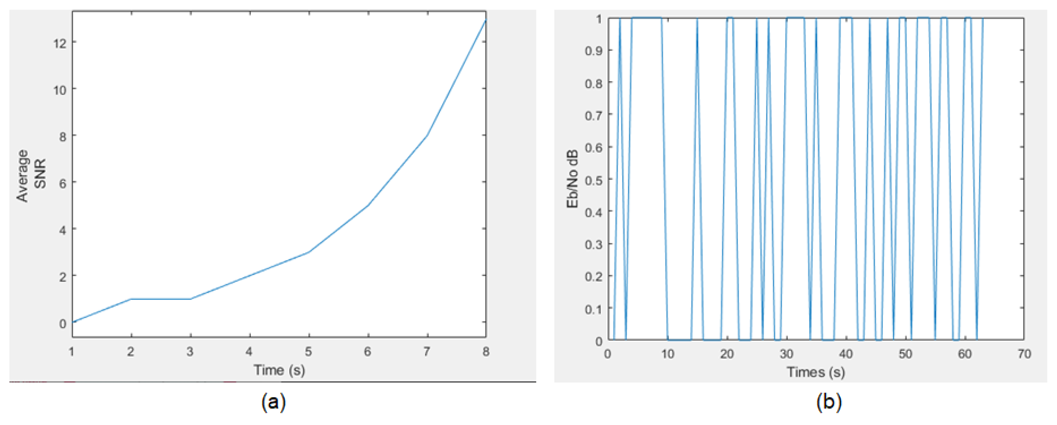
Figure 6 below shows the simulation results of the Berlekamp–Massey algorithm and its modified variant; the images represent the noise resistance during communication over a Li-Fi network. We notice that the existence of noise is quite regular for the modified BM, unlike for the noise in (
Figure 6b). This represents an advantage to adapt the modified BM algorithm.
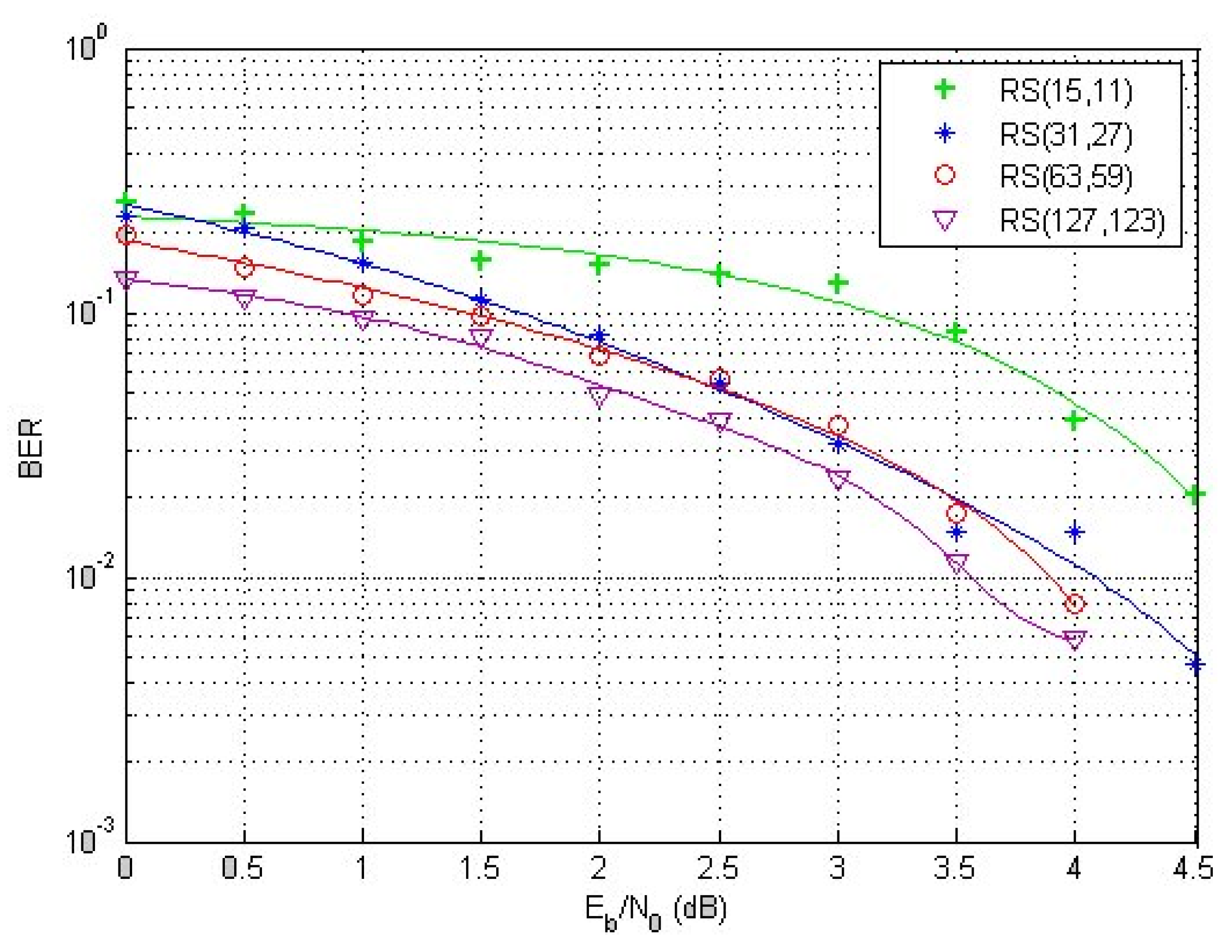
Figure 7 represents an example of the RS code flow for error correction: (15,11), (31,27), (63,59), and (127,123). The above graph shows that the error-correcting Reed–Solomon codes become more efficient as the code size grows, since the noise impact decreases with a larger code size. Furthermore, for bigger code words, the noise duration must represent a relatively small proportion, and the received noise must be averaged over a lengthy period of time. For large block sizes, the Reed–Solomon codes are favored. This indicates that the ideal big size code word represents a step forward in terms of performance. On the other side, a very high size code word will complicate transmission implementation.
Choice of Reed–Solomon
A comparison with other corrector codes was made [
15]; the results of this comparison are presented in
Table 3.
The comparison is based on the speed of encoding/decoding of these codes; which is an important argument as these codes are often used to transmit information in real-time, on the efficiency to the noise resistance, and the ability to correct a larger number of errors.
The security of encoding and decoding is also an essential consideration in the selection of Reed–Solomon codes. Other corrective codes, such as the Hamming code, are considerably more difficult to identify and fix transmission faults than Reed–Solomon codes, which detect problems the first time they occur.
According to the table (
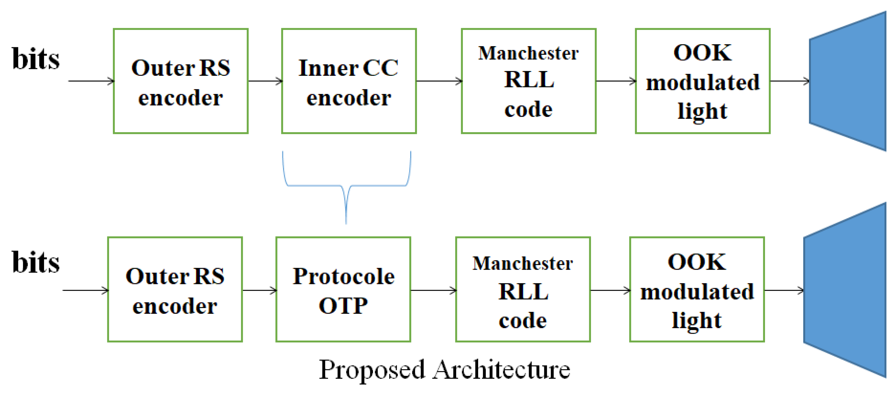
Table 3), RS codes have a very high resistance to noise, which represents a major factor for our study; moreover, RS codes have a great capacity to correct the greatest number of transmission errors. These codes are also used in on–off keying modulation in the proposed architecture; hence, the choice of these codes for error correction. The variable p is an integer representing the probability of the existence of noise.
5. Conclusions and Future Works
The idea cited in this paper is to use the Berlekamp–Massey algorithm for the one time pad for the generation of pseudo-random keys, and whose algorithm has been modified by adding a degree of security. These pseudo-random keys will depend on the value of k, which represents an odd number different from 1 and is chosen by the sender of a message, and we will use this value thereafter to encode and decode the message. We will be able to tweak the algorithm such that the value of k varies with each communication and key creation, ensuring that the method will never be broken on the network because our notion is dependent on the value of k. The sender and receiver will use the same protocol to encode and decode the message during transmission. Although Li-Fi systems are more secure than RF systems, our approach is introduced as a security accomplishment for this system, and allows information to be exchanged securely across the network and to protect users, as long as each message has its own key, the sharing of these secret keys will be conducted in a secure way. In terms of complexity, our method has a complexity of O(L2) for both encoding and decoding. Another advantage of this technique is that, even if the intruder understands the encryption algorithm, the intruder will be unable to decode a message, since he/she lacks the value of k required to encode and decode the message. According to our estimates, even if the method is changed, the error correcting aspect will remain unchanged. The suggested technique addresses the shortcomings of various current approaches based on generating secret keys, the most significant of which is the requirement to transmit the shared key. This must be done with extreme caution to avoid revealing the key to unwanted users. There might also be an issue with the amount of keys utilized. When you have a big number of keys, it might be tough to keep track of them all. This new approach allows a more secure communication through the network. Our motivation to propose this idea is to be able to disseminate this concept in hospitals, especially in this period of a global health crisis. The issue determines how to monitor each patient while maintaining the confidentiality of their information.
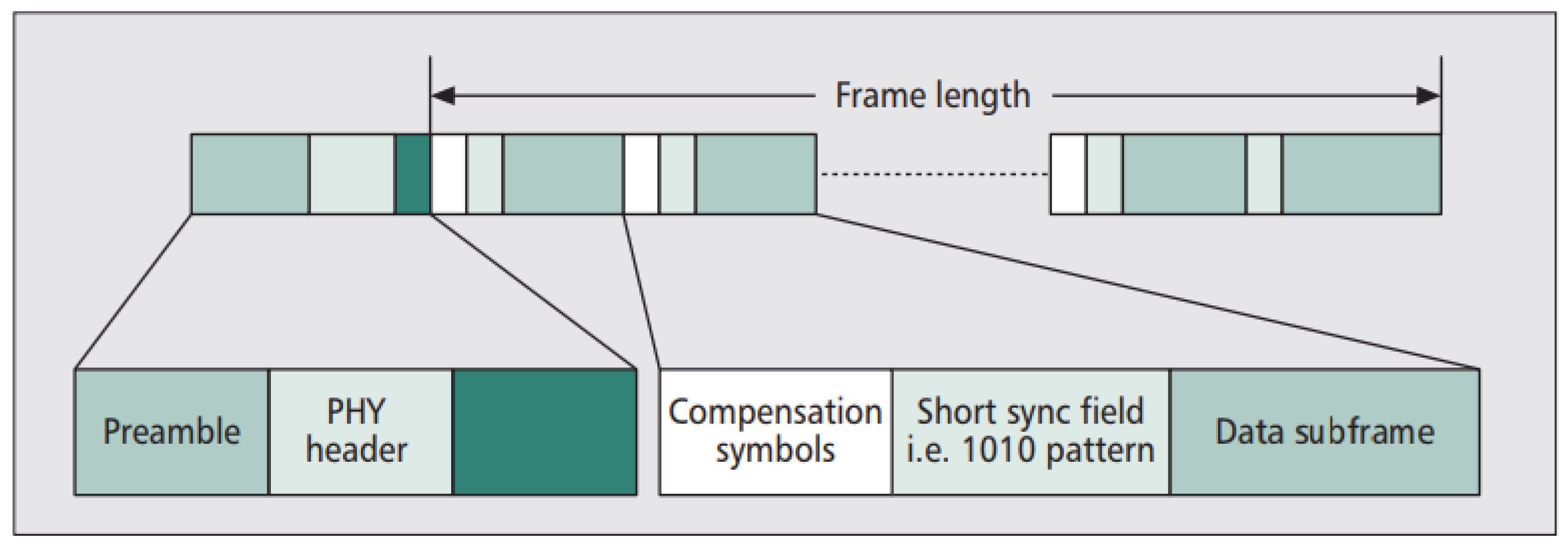
In future work, we will review the Manchester coding at the physical frame level and develop it to be able to code the outgoing signal. We also want to work more on OFDM modulation for secret key generation.


