Abstract
In order to ease the conflict between the bandwidth demand of high-rate wireless communication and the shortage of spectrum resources, a wideband spectrum sensing method based on reconfigurable filter bank (RFB) with adjustable resolution is presented. The wideband signals are uniformly divided into multi-narrowband signals by RFB, which is designed by polyphase uniform Discrete Fourier Transform (DFT) modulation, and each sub-band is sensed by energy detection. According to the idle proportion of detected sub-bands, the number of RFB sub-bands is reset in next spectrum-sensing time. By simulating with collected wideband dataset, the influence of filter bank sub-bands number and idle state proportion on the sensing results is analyzed, and then on the basis of the trade-off between spectrum-sensing resolution and computational complexity, the optimal sub-bands number of filter bank is selected, so as to improve the detection performance and save resources.
1. Introduction
It is a common fact that a large amount of spectrum resources get stuck in an extremely low utilization resulting from the fixed allocation mechanism. This apparently has become a severe headache confronting the demand for high-rate wireless communication technology and the shortage of spectrum resources. Being a hotspot in industry, Cognitive Radio (CR) is quite impressive in its ability to detect and utilize idle spectrums. The secondary user (SU) in CR may discover an idle band with the help of spectrum-sensing technology. This is a free frequency band that may, with no time-consuming interval waiting for the primary user (PU), provide an opportunistic access to the idle licensed band, thereby boosting the spectrum utilization. Nevertheless, this may fail to work when dealing with the rapid expansion of demand for wireless spectrum resources ranging from 6 kHz to 300 GHz. More spectrum access opportunities are only be available in the CR spectrum-sensing environment, which may be extended to a few GHz wideband scenarios [].
Unlike the narrowband ones, the wideband spectrum-sensing method is able to help users find more spectrum idle opportunities, thus achieving a higher throughput on a wide frequency band. Due to the high data rate of the wideband channel, the sampling rate has been viewed as a bottleneck of wideband spectrum-sensing technology. As far as sampling rate is concerned, wideband spectrum-sensing is either based on the sub-Nyquist (lower than Nyquist sampling rate) sampling rate [] or the Nyquist sampling rate. The former is famous for compressive sensing [] that needs the reconstruction of sampled signals, which is of high complexity and difficult to implement or apply in engineering practice. The compressive sensing may be problematic due to its precondition that the wideband must be sparse for all signals. The latter may be obtained in different approaches, including wavelet detection [], multiband joint detection [] and a detection method based on the filter bank (FB) []. The wavelet detection is taken as alternative that works on the wavelet transform to detect the edge of the discontinuous sub-bands. Such discontinuity may be found in the spectrum in the absence of the PU or not, making it possible to determine the location of the free sections in the wideband spectrum. The multiband joint detection converts the serial wideband signals from high-speed sampling into multiple parallel narrowband signals, judging whether or not the PU signal exists for each sub-band, the key of which is the selection of detection threshold for each sub-band. The simplest way is to select the same threshold, and the joint optimization is available to select the detection threshold of each channel aiming to promote the detection results. Both of the above methods demand high sampling rate and hardware processing speed.
Based on the FB, the wideband spectrum is divided into multinarrow bands, followed by sampling and processing the filtered narrowband signals. Due to the lower spectral leakage property compared with taking fast Fourier transform (FFT) at the ADC sampling rate, the polyphase filter bank (PFB) is widely applied to wideband spectrum sensing. Study in [] presents a multiband energy detection method based on PFB and the closed-form expressions of detection probability and false alarm probability for PFBs are derived, which performs better than the conventional FFT. A two-stage wideband spectrum-sensing utilizing PFB in [] reduces the number of binary detections when the number of occupied primary channels is small, otherwise, the number of binary detections is larger than the total number of primary channels. Multistage PFB is applied in [] to reduce the computational complexity and improve the detection accuracy simultaneously, which needs to estimate the center frequency of the signals. Because of less delay and power requirements, Discrete Fourier Transform Filter Bank (DFTFB) is usually employed to spectrum sensing []. In [], a tree-structured DFTFB is presented for detecting the edges of channels. Another study in [] proposes a modulated FB combined polyphase and DFT for less complexity.
In recent years, obtaining wideband spectrum states based on estimation or prediction has caught the attention of many researchers, which could reduce the detection time by estimating or predicting the channel state instead of directly detecting each channel. In this regard, two-dimensional frequent pattern mining is commonly used [], but to identify frequent patterns requires a large amount of calculations, which also vary in different environments. Another action to take is the wideband spectrum prediction based on channel correlation clustering and estimation [,], which would deal with wider bandwidth than 1 GHz, but the prediction accuracy may not meet the needs of SUs, for it is based on statistics.
Mostly, the wideband spectrum-sensing methods have either been constrained at the theoretical level due to processing speed in hardware and inherent complexity in implementation, or have low detection accuracy. Method based on the FB is achievable, which is advanced that makes a detour around the technical bottleneck of directly processing wideband signals, making it less demanding for hardware processing speed, yet rarely able to adjust the resolution dynamically. The RFB is available for adjusting the spectrum-sensing resolution by changing the number of divided sub-bands, which means the varying number of sub-bands in FB. Based on the fast filter bank (FFB), the variable bandwidth FB [] is configurable with a cascade structure, where each stage of the prototype low-pass filter needs to be designed separately. As the number of divided sub-bands increases, the computation gets even more complexity. The coefficient decimation filter bank (CDFB) [,] serves to decimate, configure and store the coefficients of the calculated prototype filter to change the sub-band bandwidth, which is yet held back by more storage space and high complexity.
Because computational complexity and detection accuracy both depend on the number of sub-bands in the FB, it is necessary to develop RFB to balance the above two contradictions. For simplicity, an easy-to-go improved polyphase DFT filter bank (P-DFTFB) [] for real signals is adopted to design reconfigurable FB in this paper. Coefficient decimation is performed to obtain a variable bandwidth in the FB, and the last spectrum-sensing result provides a feedback on how to select the number of FB sub-bands for the next detection time, in attempt to achieve a wideband spectrum sensing with adjustable resolution and reduce the complexity.
2. System Model
Considering the user’s needs, the spectrum bandwidth to be sensed by the SUs is greater than 2 GHz in this work. If the wideband spectrum sensing is directly performed, a complex FB is required, which is unacceptable in practical systems, especially mobile devices, where power consumption and its size are critical. If only wideband spectrum prediction is performed, the perceived accuracy may not reach the needs of the cognitive user. Therefore, the research method adopted in this work is a combination of rough estimation and fine sensing. In the rough estimation stage, the wideband spectrum is firstly divided into multiple sub-bands, which then are clustered based on the correlation between sub-bands. Subsequently, one detection sub-band is selected for direct detection of the clustered sub-bands, while the state of other sub-bands in the same group is obtained by way of prediction or estimation. Finally, the sub-bands selected by the rough estimation with different transmission services are accurately sensed based on RFB, as shown in Figure 1.
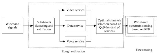
Figure 1.
Rough estimation and fine sensing of wideband spectrum.
The conventional narrowband energy detection (ED) is able to determine whether the channel is occupied by comparing the detection statistic of the received signal with the pre-set threshold. For wideband spectrum, the RFB divides the received wideband signals into sub-bands, applying the ED for each independent sub-band for spectrum sensing. Judging by the number of detected idle or occupied sub-bands, the number of RFB sub-bands is adjusted accordingly. The system block diagram is shown in Figure 2. The detection statistic of each sub-band is compared with the same threshold, and the decision center is responsible for determining the adjustment of the FB sub-band number. The SU would no longer sense the channels during a data transmission period—that is, the channel state is assumed to be unchanged. If the data transmission fails, the channels need to be re-sensed. Otherwise, the channels states are obtained again prior to the next data transmission period.
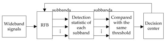
Figure 2.
Wideband spectrum sensing with a RFB.
3. Design of Reconfigurable P-DFTFB
This section provides the design of improved P-DFTFB for real signals and the reconfiguration method of RFB.
3.1. Design of Analysis P-DFTFB
The conventional FB is structurally made in a lattice network or a tree cascade. Note that the number of divided sub-bands may increase to sharply put on more computational complexity of both structures, so it is not suitable for the large number of sub-bands. With a parallel structure, the polyphase uniform DFT modulation counts on an analysis FB that is modulated by the prototype low-pass filter, featuring a simple computational structure with lower complexity. The polyphase decimation is there to quicken the subsequent filtering and FFT operation. Having equipped with a P-DFTFB, wideband spectrum sensing technology exhibits attractive frequency characteristics being capable of eliminating the influence of aliasing. Its implementation structure is so efficient to be able to greatly fascinate the processing course of the whole system. This is truly remarkable and therefore widely welcomed in wideband spectrum sensing technology.
Assume that the wideband input signal is , the number of sub-bands to be divided is , and the prototype filter is a low-pass FIR filter, with in length, as . is an integer multiple of , which is an integer power of two, i.e., and is an integer. The polyphase structure of the filter acts to get less computational burden and hardware complexity. The prototype filter has a transfer function , which is defined as:
Let be expressed by polyphase decomposed form with polyphase branches as:
where and . For are the polyphase branches of , represented by , then
Therefore, is expressed as:
According to the definition of DFT, Equation (4) is a DFT transform of . So, the filter is implemented by a polyphase system followed by DFT modulator.
The precondition such as center frequency is unnecessarily known in advance for input wideband signal when it is decomposed into sub-band signals, and the sampling rate of each sub-band is reduced to of the original. At the same time, the prototype filter coefficient is divided into polyphase branches as . To keep the data rate in a lower level with less complexity, the prototype filter coefficient is decimated with times. It is known that the equivalent transformation principle of the network structure should be followed in the multisampling rate system, so the signal delay of samples is given a -times decimation, which is equivalent to decimate times and then delay one sample. The sub-band division block diagram can be obtained for the P-DFTFB as shown in Figure 3. The output of each sub-band is , if is an integer power of 2, an FFT operation may be performed to supersede the DFT operation. Meanwhile, the P-DFTFB from critical decimation (the decimation times is equal to the number of divided sub-bands) satisfied the reconstruction condition, so it does not need to demonstrate the reconfigurability of the FB, and the integrated FB will not be taken into account in the FB design.
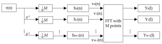
Figure 3.
Sub-bands division based on P-DFTFB.
As shown in Figure 3, the input signal transforms to after M-times decimating and polyphase filter, where .
Taking the eight sub-bands as an example, the polyphase uniform DFT analysis FB provided the ideal frequency response as shown in Figure 4. Apparently, the m-th sub-band system function is measured from the frequency shift by the prototype filter system function , that is
where .
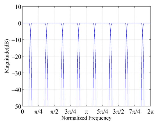
Figure 4.
Ideal frequency response of the P-DFTFB.
3.2. Design of Improved Analysis P-DFTFB
Figure 4, when the input signal is real value, the bandwidth of is only half of the other bandwidth. To make sure that all output sub-bands has the same bandwidth in actual use, the improvement shown in Figure 5 takes on the stage. In this DFT analysis structure, the center frequency of the 0-th sub-band filter is shifted to the right by . The ideal frequency response of the modified 8 sub-band analysis FB is as shown in Figure 6. At the m-th branch, the multiplication of the factor can be achieved by multiplying the coefficient of with a factor of .
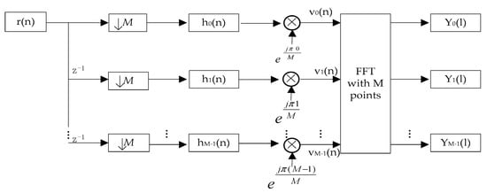
Figure 5.
Sub-bands division based on improved P-DFTFB.
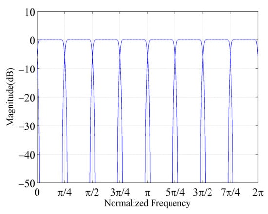
Figure 6.
Ideal frequency response of the improved P-DFTFB.
Right now, , where, and the final output of each sub-band is
3.3. Reconfiguration
The reconfiguration of P-DFTFB is realized by changing the number of the sub-bands in FB. The selection and configuration of is key to the reconfigurable filter banks. In [], there is an upper confidence bound (UCB)-based decision making stage to select the sub-bands number and decide the central frequency of each sub-band, which has high complexity. The decision-making method based on learning algorithms in [] consumes a lot of time to learn. So, we propose a simple decision-making method as Algorithm 1 in Section 4.2 to select the sub-bands number according to the last sensing result.
4. Wideband Spectrum-Sensing Based on RFB
In this section, we present the energy detection for sub-bands based on RFB and its performance evaluation parameters. According to the sensing result, selection algorithm of RFB sub-bands number is proposed.
4.1. Energy Detection for Sub-Bands
is the input signal at the receiving end. Assume that the channel noise is an additive white Gaussian noise with a mean of 0 and a variance of , and the PU transmission signal is , then:
when there is no PU user: ;
when there is a PU user: .
After the input signal is processed by the RFB, the m-th sub-band gets the received signal as . According to the energy detection principle, each sub-band selects the same threshold value . Comparing the detection statistics of with , if is smaller than , the sub-band is viewed as idle, represented by “0”, and if is greater than or equal to , it is determined that the sub-band is occupied, represented by “1”, which is represented as:
The energy detection performance of each sub-band is evaluated by the detection probability and the false alarm probability , which are defined as follows:
which means that indicates the probability of the detection result being occupied when the sub-band is occupied, indicates the probability of the detection result being occupied when the sub-band is idle, and the probability of misdetection is expressed as , indicating the probability of the detection result being idle when the sub-band is occupied.
According to the central limit theorem, when , may be approximated as a Gaussian random process, where and are expressed as:
where is the power of the transmitted signal , is the tail probability of the standard zero-mean Gaussian random variable, i.e., .
When the values of and are constant, the selection of the decision threshold has effects on and . A larger would lead to a larger , and a larger . If is too large, the false alarm may cause the cognitive user to miss many opportunities for spectrum utilization, resulting in lower spectrum utilization. If is too small, a large number of PU signals may be missed, increasing interference to authorized users. Therefore, presents the optimization result of maximizing and minimizing . Generally, when is given, the threshold may be derived from Equation (12) as:
where is the inverse function of , and because , the threshold is expressed as:
Working with the FB, the wideband spectrum detection probability is obtained from the average detection probability of each sub-band, i.e.,
4.2. Selection of RFB Sub-Bands Number
If the FB sub-bands number is too small, the calculation involved would be in a smaller amount. The problem is that there is severe aliasing between the spectrums, leading to a lower spectrum detection resolution. For a larger , the sub-band bandwidth gets smaller, along with more FFT points as shown in Figure 5. As a result, the spectrum detection performs better to some extent, yet the order N of the prototype filter is augmented. The computational workload that comes with it would go up dramatically. Therefore, under the condition that the performance requirements of the FB is satisfied, the number of sub-bands of the FB is adjusted in real time to meet the occupancy of each sub-band, so as to reduce the calculation amount and improve the detection efficiency and performance.
The idle state proportion and occupancy state proportion of the wideband spectrum are and , respectively, which are statistically obtained from the occupancy of each sub-band, expressed as:
where is the number of free sub-bands, and is the number of occupied sub-bands, and .
The detected idle state proportion and occupancy state proportion of the wideband spectrum is and respectively, which are obtained from the detected occupancy of each sub-band, expressed as:
where stands for the number of idle sub-bands detected, is for the number of sub-bands when their states are idle and the detected values are also idle, and indicates the number of sub-bands when their states are occupied but the detected values are idle. The number of sub-bands is determined by the misdetection probability , and indicates the detected number of occupied sub-bands, and is the number of sub-bands when their states are occupied and the detected values are also occupied, and represents the number of sub-bands when their states are idle but the detected values are occupied, which is measured with the false alarm probability , and .
For reconfigurable P-DFTFB, only the number of sub-bands is reset. Since the input signal bandwidth is a constant value, the number of sub-bands dominates the resolution of the spectrum detection. Therefore, the spectrum detection result of each sub-band controls the adjustment of the FB division on the sub-band number , and is in a range of 4–256. The pseudo code of the algorithm to select is described as follows (Algorithm 1).
| Algorithm 1 Selection of |
| 1: Initialization: . 2: If , if end else end 3: If , if end else end 4: Otherwise, the would be unchanged at the next sensing time. |
The initial value of is the common value of the FB used to divide sub-bands, that is, . In view of the current spectrum detection result, the adjustment of the at the next sensing time is made and divided into three cases: increasing, decreasing or not changing.
If the current detection result is , according to Equation (18), it shows that the value of may be large, and it is necessary to reduce . From Equation (14), when the value of is added, the value of becomes larger, leading to a larger value of and a smaller . Therefore, the value of M is increased to two times in the next sensing time, and the current sensing ends. If the change of two detections with two adjacent is less than 5%, that is , the would not be changed in the next sensing time, for the detection performance is not much better even with an added value of .
If the current detection result is , Equation (19) shows that the value of may be larger, and needs to be reduced. It is known from Equation (14) that the a reduced value of results in the value of to be decreased, and may come down to reduce . Therefore, the value is reduced to half of the original at the next sensing time, and the current sensing time ends. If the change of two detections with two adjacent is greater than 10%, that is , then the would be unchanged at the next sensing time, for the detection performance could be more deteriorated after the is adjusted.
If the detection results are not the above values, the current sensing ends, and the value of remains unchanged at the next sensing time.
5. Simulation Results and Analysis
5.1. Data Preprocessing
Real signals employed in our work are the Power Spectral Density (PSD) values measured by RWTH Aachen University in 2007 with the platform of Agilent E4440A spectrum analyzer at three different places as IN (indoor), NE (rooftop) and AB (third floor balcony), respectively, and the dataset covers the frequency range from 20 MHz to 6 GHz with the time of one week []. For the proposed method, which is based on RFB, is a fine sensing method used after optimal channels selection in rough estimation. The NE (rooftop) sub-band 1 300 MHz–700 MHz band with 24-hour measurements data of PSD values is applied in the next simulation. The spectrum occupancy is shown in Figure 7a, where the resolution is 200 kHz, plus the average sampling interval of 1.8 s and the power unit in dBm. As the measurement dataset is quite large, one sample value is taken every 60 measured data in time, and the energy threshold is set to –107 dBm/200 kHz based on the IEEE 802.22 standardization committee for the detection threshold of wireless microphones. Alternatively, when the sampling power value is greater than the energy threshold, the sub-band is occupied and represented by “1”, otherwise the sub-band is idle and represented by “0”.
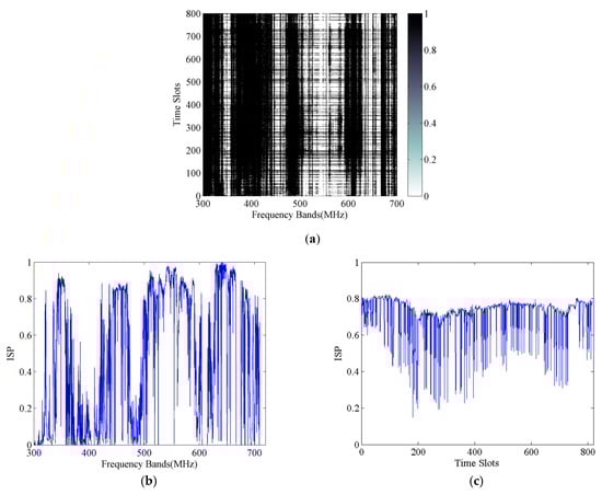
Figure 7.
Twenty-four-hour PSD data preprocessing in 300 MHz–700 MHz band. (a) Sub-bands occupancy; (b) ISP in the frequency domain; (c) ISP in the time domain.
The sub-bands idle state proportion (ISP) is the ratio of the number of sub-bands of an idle state to the total number of sub-bands, and Figure 7b,c count the ISP from the frequency domain and the time domain, respectively. Figure 7b shows that some adjacent sub-bands have higher ISP, such as the 350 MHz and 550 MHz bands. In Figure 7c, observe that the sub-bands’ ISP continues to be high for a fraction of the continuous time. Apparently, the spectrum utilization rate is low, so that the cognitive user is able to improve spectrum utilization through the combination of both the spectrum sensing technology and dynamic spectrum access technology.
The prototype filter for FB is a FIR filter implemented in MATLAB with respect to the Remez algorithm simulation. The stop-band attenuation reaches –50dB and satisfies the condition of the linear phase. The prototype filter coefficient is decimated and divided into polyphase branches to form P-DFTFB. The real signals of PSD values are transformed to amplitude measurements and then filtered by the proposed P-DFTFB. The example of eight sub-bands divided by P-DFTFB is shown in Figure 8, and the X label is the normalized frequency of each sub-band, and the actual value of ISP is about 0.6.
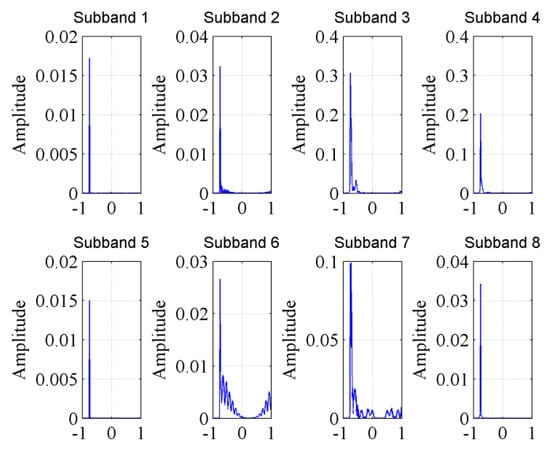
Figure 8.
Amplitude spectrum of eight sub-bands.
As shown in Figure 8, the signals amplitudes of Sub-band 3, Sub-band 4 and Sub-band 7 are higher than the others obviously. Given a proper threshold, the sub-band state would be obtained by comparing the detection statistic with the threshold, and the above three sub-bands maybe determined as occupied, therefore, the measured ISP is 0.625 which is approximate to the actual value 0.6.
5.2. Wideband Spectrum Sensing Based on RFB
At three different sensing times, taking 2048 samples in the dataset of NE sub-band 1, 300 MHz–710 MHz frequency band, the sub-bands ISPs are 12.27%, 47.51%, and 80.38% respectively. After the sampled data is processed by the FB, the energy detection method is employed for each sub-band to perform spectrum sensing. The detection threshold is determined by Equation (13) at different false alarm probabilities, and the detection probability is determined by Equation (15). ROC curves on the wideband spectrum sensing are shown in Figure 9, with different sub-bands numbers divided by RFB, and the is higher, the detection performance is better. is preset for changing the threshold according to Equation (14).
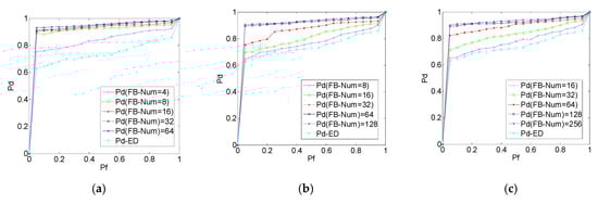
Figure 9.
ROC curve for sub-bands with different ISPs. (a) ISP is 12.27%; (b) ISP is 47.51%; (c) ISP is 80.38%.
As can be seen from the ROC curve, the wideband spectrum sensing based on the FB performs much better than the direct energy detection method. Furthermore, the optimal number of sub-bands divided by the RFB is not necessarily the number that the hits the maximum, but relates to the ISP of the sub-bands. In Figure 9a, when the sub-bands ISP is at a low level, fewer FB sub-bands are needed to reach the requirements of detection performance, and eight sub-bands are suitable. But in Figure 9c, when the sub-bands ISP is at a higher level, more FB sub-bands are essential to achieve the required detection accuracy, and the optimal is 128. In Figure 9b, the rises along with the bigger , but when the becomes greater than 64, no further improvement of is identified. Consequently, the appropriate number of RFB sub-bands is selected by weighing the detection performance and the computational complexity.
6. Conclusions
In this paper, we propose an alternative method to reconfigure the number of RFB sub-bands based on spectrum-sensing results and sub-bands ISP. First, a P-DFTFB is especially designed for uniform division of the wideband signals into multiple sub-band signals, and the energy detection method is applied to confirm the occupancy status of each sub-band. Moreover, the number of RFB sub-bands is reset to come up with the ISP of the current detection. That is, for a higher sub-band ISP, more RFB sub-bands may be divided to achieve the required detection performance. If the ISP is low, the number of RFB sub-bands would be reduced to ease the burden of calculation. The simulation results show that the proposed wideband spectrum-sensing method with a RFB outperforms the energy detection method. Specifically, the number of RFB sub-bands may well be adjusted with the ISP, and ultimately, will greatly improve the detection performance along with less calculation work.
Author Contributions
H.W. designed the RFB and wideband spectrum-sensing method, and wrote the paper. B.W. helped with analysis the sensing model. Y.Y. helped to perform the data processing and simulation model. M.Q. helped with data analysis and the editing of this paper.
Funding
This research is funded by the National Key Research and Development Project under Grant 2016YFF0104000, in part by the Science and Technology Planning Project of Sichuan Province under Grant 2019YJ0309, in part by the Sichuan Education Department Funded Project under Grant 18ZB0611, in part by the Longshan Academic Research Support of Southwest University of Science and Technology under Grant 17LZX318 and 17LZX319.
Acknowledgments
We are grateful for the Spectrum Data Archive of the Institute of Networked Systems at RWTH Aachen University for providing wireless data.
Conflicts of Interest
The authors declare no conflict of interest.
References
- Chen, Y.F.; Oh, H.S. A Survey of Measurement-based Spectrum Occupancy Modeling for Cognitive Radios. IEEE Commun. Surv. Tutor. 2016, 18, 848–859. [Google Scholar] [CrossRef]
- Ma, Y.; Gao, Y.; Cavallaro, A.; Parini, C.G.; Zhang, W.; Liang, Y.C. Sparsity Independent Sub-Nyquist Rate Wideband Spectrum Sensing on Real-Time TV White Space. IEEE Trans. Veh. Technol. 2017, 66, 8784–8794. [Google Scholar] [CrossRef]
- Mohsen, G.; Ali, S. Adaptive data-driven wideband compressive spectrum sensing for cognitive radio networks. J. Commun. Inf. Netw. 2018, 3, 84–92. [Google Scholar]
- Dibal, P.Y.; Onwuka, E.N.; Agajo, J.; Alenoghena, C.O. Application of wavelet transform in spectrum sensing for cognitive radio: A survey. Phys. Commun. 2018, 28, 45–57. [Google Scholar] [CrossRef]
- Saeedzarandi, M.; Azmi, P. Cooperative multiband joint detection in cognitive radio networks using artificial immune system. Ann. Telecommun. 2013, 68, 239–246. [Google Scholar] [CrossRef]
- Smitha, K.G.; Vinod, A.P. A Multi-Resolution Fast Filter Bank for Spectrum Sensing in Military Radio Receivers. IEEE Trans. Very Large Scale Integr. (VLSI) Syst. 2012, 20, 1323–1327. [Google Scholar] [CrossRef]
- Zhang, H.J.; Ruyet, D.L.; Roviras, D.; Sun, H. Polyphase filter bank based multi-band spectrum sensing in cognitive radio systems. Int. J. Commun. Syst. 2016, 29, 1844–1862. [Google Scholar] [CrossRef]
- Zheng, S.L.; Yang, X.N. Wideband spectrum sensing based on group testing utilizing polyphase filter banks. In Proceedings of the 2014 19th International Conference on Digital Signal Processing, Hong Kong, China, 20–23 August 2014; pp. 592–596. [Google Scholar]
- Samuel, C.P.; Kankar, D.S. A Low-Complexity Multistage Polyphase Filter Bank for Wireless Microphone Detection in CR. Circuits Syst. Signal Process. 2017, 36, 1671–1685. [Google Scholar] [CrossRef]
- Smitha, K.G.; Vinod, A.P.; Nair, P.R. Low power DFT filter bank based two-stage spectrum sensing. In Proceedings of the International Conference on Innovations in Information Technology (IIT), Abu Dhabi, UAE, 18–20 March 2012; pp. 173–177. [Google Scholar]
- Narendar, M.; Vinod, A.P.; Madhukumar, A.S.; Krishna, A.K. A tree-structured DFT filter bank based spectrum sensor for estimation of radio channel edge frequencies in military wideband receivers. In Proceedings of the 10th International Conference on Information Science, Signal Processing and their Applications (ISSPA 2010), Kuala Lumpur, Malaysia, 10–13 May 2010; pp. 534–537. [Google Scholar]
- Kim, C.; Shin, Y.; Im, S.; Lee, W. SDR-based digital channelizer/de-channelizer for multiple CDMA signals. In Proceedings of the Vehicular Technology Conference Fall 2000, Boston, MA, USA, 24–28 September 2000; pp. 2862–2869. [Google Scholar]
- Yin, S.X.; Chen, D.W.; Zhang, Q.; Liu, M.Y.; Li, S.F. Mining Spectrum Usage Data: A Large-Scale Spectrum Measurement Study. IEEE Trans. Mob. Comput. 2012, 11, 1033–1046. [Google Scholar]
- Gao, M.F.; Yan, X.; Zhang, Y.C.; Liu, C.Y.; Zhang, Y.F.; Feng, Z.Y. Fast Spectrum Sensing: A Combination of Channel Correlation and Markov Model. In Proceedings of the 2014 IEEE Military Communications Conference, Baltimore, MD, USA, 6–8 October 2014; pp. 405–410. [Google Scholar]
- Huang, S.; Feng, Z.Y.; Yao, Y.Y.; Zhang, Y.F.; Zhang, P. Multi-centers cooperative estimation based fast spectrum sensing. In Proceedings of the 2016 IEEE International Conference on Communications (ICC), Kuala Lumpur, Malaysia, 22–27 May 2016; pp. 1–6. [Google Scholar]
- Hao, J.G.; Pei, W.J.; Xia, Y.L.; Wang, K. Design of low complexity reconfigurable variable bandwidth filter bank. J. Electron. Meas. Instrum. 2015, 29, 1057–1063. [Google Scholar]
- Darak, S.J.; Vinod, A.P.; Lai, E.M.K. A low complexity reconfigurable non-uniform filter bank for channelization in multi-standard wireless communication receivers. J. Signal Process. Syst. 2012, 68, 95–111. [Google Scholar] [CrossRef]
- Ambede, A.; Smitha, K.G.; Vinod, A.P. A Low-Complexity Uniform and Non-uniform Digital Filter Bank Based on an Improved Coefficient Decimation Method for Multi-standard Communication Channelizers. Circuits Syst. Signal Process. 2013, 32, 2543–2557. [Google Scholar] [CrossRef]
- Lee, D.; Kim, D.S.; Lim, C.M. Performance analysis of frequency hopping satellite communication system reducing the transient response of Polyphase DFT filter. In Proceedings of the 20th Asia-Pacific Conference on Communication (APCC 2014), Pattaya, Thailand, 1–3 October 2014; pp. 199–202. [Google Scholar]
- Darak, S.J.; Palicot, J.; Zhang, H.G.; Prasad, V.A.; Moy, C. Reconfigurable Filter Bank With Complete Control Over Subband Bandwidths for Multistandard Wireless Communication Receivers. IEEE Trans. Very Large Scale Integr. Syst. 2015, 23, 1772–1782. [Google Scholar] [CrossRef]
- Jiang, T.; Grace, D.; Liu, Y. Two-stage reinforcement-learning-based cognitive radio with exploration control. IET Commun. 2011, 5, 644–651. [Google Scholar] [CrossRef]
- Wellens, M.; Mahonen, P. Lessons learned from an extensive spectrum occupancy measurement campaign and a stochastic duty cycle model. In Proceedings of the 2009 5th International Conference on Testbeds and Research Infrastructures for the Development of Networks & Communities and Workshops, Washington, DC, USA, 6–8 April 2009; pp. 1–9. [Google Scholar]
© 2019 by the authors. Licensee MDPI, Basel, Switzerland. This article is an open access article distributed under the terms and conditions of the Creative Commons Attribution (CC BY) license (http://creativecommons.org/licenses/by/4.0/).