1. Introduction
Internet of Things (IoT) applications will bring huge amounts of information data processing, including not only text, but also multimedia data such as audio and video. As the multimedia data perception layer of the IoT, wireless multimedia sensor network (WMSNs) has been widely used in various fields, including target monitoring, tracking and environmental monitoring. Multimedia data requires high bandwidth and delay, so it is necessary to establish multipath routing for transmission. Independent multipath routing can improve network throughput and work efficiency and minimizing overlap between multipaths can help WSN nodes to use energy equally to reduce black hole phenomenon.
Resource-constrained wireless sensor nodes are prone to congestion in high-load applications, which significantly affects network performance [
1,
2,
3]. In order to solve this problem, researchers have adopted more network resources to improve network capacity and adopted the method of multi-path average network traffic to support the bandwidth requirements of different applications to solve the problem of network congestion. Moreover, sending network traffic through multiple sensors will reduce the average energy consumption of sensor nodes and prolong the network lifetime. In the past decade, multipath routing has been widely used for various purposes, such as improving the reliability of data transmission, providing fault-tolerant routing, congestion control and quality of service (QoS) support. In single-channel wireless networks, because of the broadcast characteristics of wireless communication, sensor nodes use shared wireless channels to communicate with adjacent paths. Intensive concurrent communication may cause interference and increase the probability of packet collision between active path nodes. This problem is called path coupling effect, which limits many of them. This problem poses a challenge to the design of efficient multipath routing protocols. In order to reduce the interference between multipath routing, designing independent and disjoint paths becomes the main standard for designing multipath routing protocols. The main contributions of this paper are summarized as follows:
- (1)
On the premise of satisfying the application delay, using the idea of software definition, the independent multi-path routing is formed by fitting multiple curves. A multi-source multi-path routing algorithm is proposed, which takes into account the balance of delay and energy consumption.
- (2)
Aiming at the problem of privacy disclosure of communication relationship, a node hidden communication model is designed for the IoT. In this covert communication system, the attack detection and prevention technology is studied, which effectively improves the anti-attack ability.
The structure of this paper is as follows: chapter 2 introduces the related research on Multimedia Routing Algorithm in the IoT. chapter 3 introduces the system model in detail. chapter 4 introduces the design of multimedia independent multipath routing algorithm. chapter 5 introduces the implementation process of multimedia independent multipath routing.
2. Relevant Research
With the development of hardware technology, WMSNs have been widely used in various fields, including target monitoring, tracking and environmental monitoring. Wireless multimedia sensor networks introduce multimedia sensors such as audio and video into wireless sensor networks. WMSNs are generally used in real-time applications with high bandwidth and low latency. In recent years, researchers have done a lot of research on routing algorithms, and many routing protocols are proposed according to the performance requirements of different applications. If multimedia data is transmitted through a single path, the energy of the forwarding node will be exhausted rapidly and the node will fail. Multipath routing method constructs multiple paths between source and target nodes, divides data into multiple paths equally, and makes more nodes participate to prolong the lifetime of nodes and networks. Data sent by multipath routing is more secure and reliable than single-path routing [
4]. Multipath routing has been widely used in different requirements, such as improving the reliability of data transmission, providing fault-tolerant routing, congestion control and QoS support. Early multipath routing was proposed based on traditional wireless sensor networks (such as ad hoc networks). To be used in wireless sensor networks, it is necessary to consider the unique characteristics of wireless sensor networks (such as limited energy supply, computing power and memory capacity) and short-range wireless communications (such as signal fading and interference) [
5,
6,
7].
Due to the large amount of multimedia information collected by WMSNs, the energy consumption of data acquisition, processing, storage, and wireless transceiver is relatively large, especially around sink nodes, energy holes are easily formed, which seriously affects the performance of WSN [
8]. The network lifetime can be improved by balancing the energy load distribution around sink nodes, and how to alleviate energy holes around sink nodes is also an important research direction.
Nodes can use location technology to obtain their own geographic location information. According to coordinate information, nodes can avoid blind flooding of routing detection packets and efficiently discover and maintain routing, which has good scalability and robustness. This paper mainly studies the multipath routing protocol based on geographic location information. Tarique et al. [
9] proposed a DGR multipath routing protocol solves the problem of bandwidth and energy limitation in real-time video streaming. From a small number of scattered video sensor nodes in wireless sensor networks (WSN), data is transmitted to sink nodes by combining forward error correction (FEC) coding. Shu L et al. [
10] offers an algorithm is a two-stage geographic path greedy protocol, which supports the shortest path routing and multipath routing around wormholes. The two phases of TPGF are based on geographic information forwarding and path optimization. Repeated execution of TGPF can find multiple paths to send data. However, it only considers the formation of multipath paths, without considering the interference between paths and traffic distribution. Chen A et al. [
11] based on the improvement of SPEED protocol, SPEED protocol maintains a transmission speed throughout the network, which is not suitable for various data types of wireless multimedia sensor networks. RTGOR designed different QoS services in terms of real-time and reliability. Aswale et al. [
12] proposed a geographic multipath routing (TIGMR) protocol based on triangular link quality metrics and minimum path interference, which discovers disjoint paths of multiple nodes in the IEEE 802.15.4 compatible network. The cross-layer routing protocol selects forwarding nodes based on triangular link quality metrics, residual energy and distance, and predicts the smallest adjacent path interference effect.
The above independent multipath routing algorithms are based on the maximum transmission distance per hop, without considering the balance of delay and energy consumption. In WMSNs applications with lax delay requirements, they can reduce the distance per hop and save energy consumption, in this section, delay and energy balance independent multipath routing algorithm is studied; When multiple source nodes send data to sink nodes through multiple paths at the same time, in order to avoid interference caused by path crossover, multiple source nodes need to coordinate transmission paths with each other. At present, there is little research on multi-source and multi-path routing. In this paper, a new multi-source and multi-path routing algorithm is proposed by applying the idea of software definition and controlling the routes of multiple source nodes centrally through sink nodes.
3. System Model
3.1. Delay Model
Each hop delay consists of four parts, ①queuing delay, the queuing delay can be neglected if unsaturated traffic is used; ②processing delay, Assuming that each node processes a constant length packet with equal delay; ③propagation delay, it can be neglected compared with other parameters; ④transmission delay, generally, with constant unsaturated traffic, the size of the packet remains unchanged, and the node does not need to wait. Therefore, the delay per hop can be simply estimated as a constant, and the end-to-end delay is proportional to the number of hops. Based on the data in reference [
13], the delay of 802.11b DCF per hop is estimated. The delay
of successful data transmission includes transmission delay
and response delay
:
RTS/CTS delay can be calculated by the following formula:
The symbols and values used are shown in
Table 1. According to
Table 1, the value of
with RTS/CTS is calculated to be 2.68 Ms. If the end-to-end delay
is specified, the delay
per hop can be calculated by the following formula:
3.2. Energy Consumption Model
Energy consumption includes four parts: ①Idle energy consumption: Nodes in the idle state consume little energy and can be ignored. ②Transmission energy consumption: Sending energy consumption accounts for the main part of energy consumption, which is related to the number of bytes sent. ③Receiving energy consumption: It is related to the number of bytes received. ④Control signal energy consumption: Assume that each node is the same.
If the size of the packet is unchanged and the transmission distance is the same, the energy consumption will be the same. Therefore, if a packet is sent from source to sink, and each hop is the largest distance transmission, and the free space transmission path index is 2, that is, the energy consumption per hop is proportional to the square of distance, then the energy model of each hop transmission is:
where
is a constant and
is a hop distance.
is the path loss index, which depends on the transmission environment, free space transmission is generally 2. For simplification, set
to 1 and
to 2. Packets send energy
through
paths
from source to target:
where
is the transmission distance from
to
hops. Then
is the source node and
is the sink node.
3.3. Transmission Model
After specifying an application delay of
, when
paths are generated between Source and Ink, and the end-to-end delay control is close to
, the energy consumption of each path is the smallest.
represents the shortest path, then
needs to satisfy
, otherwise there will be no path to satisfy q’s needs. On the other hand, Q can’t be too big. For a given network topology, multimedia applications, set the w range:
where
is constant, generally set to 2,
is the maximum transmission distance. Assuming that
is the average minimum distance per hop, there are:
When constructing
paths, the optimal transmission distance
satisfies the following formula:
Suppose that for multiple paths of
, the corresponding lengths are
. The average transmission distance per hop of the
-th path is:
can be obtained, where .
The energy consumed by the -th path is , which can be obtained by applying Cauchy inequality.
The condition of the above formula is . That is to say, when the distance per hop is equal (), the energy consumption is the smallest.
3.4. Node Hidden Communication Model
3.4.1. Correctness Analysis of Communication Model
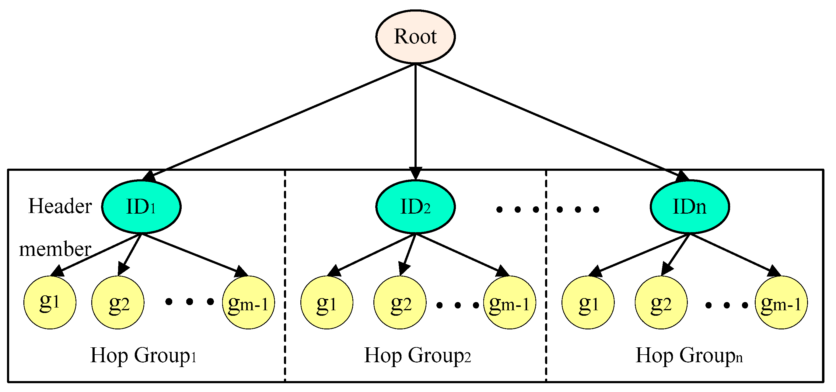
This paper introduces a model of node hidden communication, which consists of three kinds of nodes: source node composed of sender , destination node composed of receiver and relay node (Relay node ). The entry node of the forwarding network is the first row of forwarding relay nodes and the next hop of the source node, which is represented by ; the outlet node of forwarding network is the last relay node in its path and the last hop of destination node, which is represented by .
In the data forwarding network based on network coding, assuming that there is no transmission error probability, all network coding information, local coding matrix and global coding vector existing in
paths can be transmitted to the destination node, through these information, the target node can correctly recover the information sent by the source node [
14,
15].
After
network coding, information fragmentation
can be transformed into information
, the following is the specific transformation process:
The global coded vector ciphertext
is calculated by
times, and then the ciphertext
of the global encoding vector can be obtained:
By decrypting the secret key, the target node can decrypt the global encoding vector’s ciphertext
, and get the global encoding vector
:
Through the above three information, the original information can be restored fragmentally, the specific calculation method is as follows:
According to the above formulas, the following calculations can be used to derive the following conclusions:
According to , the original information can be restored.
To successfully construct an anonymous forwarding network between the sender and the receiver of information, it is necessary to satisfy the anonymity of the communication relationship between the sender and the receiver of information.
In the forwarding network, the future self-organizing anonymity of cities and counties can generate the anonymity of the senders of cities and counties with multiple virtual source nodes through the use of pseudonym strategy; the anonymity of the receiver can be realized by broadcasting information from the exit node to the target node; the anonymity of communication relationship between them can be realized through anonymous relay and forwarding network, In each hop of the forwarding network, a group of nodes is included. Each group of nodes can only understand the specific information of the group nodes of the previous and next hop, and can communicate between the group nodes, thus realizing the anonymity of the communication relationship [
16,
17].
Figure 1 shows the process of constructing forwarding network and the related anonymity strategy.
3.4.2. Anonymity Analysis
In the anonymous forwarding network, the sender sends a pseudonym , and only one precursor node exists in the collection of the entry nodes. Although it is easy to infer the sender, the inference is only a pseudonym, and the sender’s true identity is not leaked, and the sender’s anonymity is guaranteed.
In an anonymous forwarding network, the recipient’s exit node is also its precursor node, and there are in subsequent nodes, so the probability that the recipient is inferred by the exit node is only 1 m. The anonymity of the receiver is guaranteed.
In the process of constructing anonymous forwarding network, for each relay node, its information range only includes the last hop and the next hop node, and the information of other nodes is not known. In this situation, even if the attacker can intercept routing information, it is also impossible to infer the relevant information of the receiver and sender. Anonymity of communication relationship is guaranteed.
In the node hidden communication model, the anonymity of the forwarding network, sender, and receiver determines the anonymity of the model. The use of recipient pseudonym ensures that the identity of the node cannot be guessed, and the sender has the anonymity of ; The number of hop adjacent points determines the anonymity of the receiver, so the sender has the degree of anonymity; The number of forwarding nodes and the length of forwarding path determine the anonymity of forwarding network. If an attacker wants to infer the communication relationship between the receiving and sending sides of the information, he must have a detailed grasp of all the forwarding paths. Combining the probability of an attacker, one of the forwarding paths can be obtained, and the expectation of routing and forwarding paths can be expressed by . The forwarding network has anonymity. Thus, it can be concluded that the hidden communication path of the whole node has anonymity.
4. Design of Multimedia Independent Multipath Routing Algorithms
The algorithm is considered in three steps: ①Calculate the number of hops. Based on each hop delay and application specified delay, the required initial hops are calculated. ②Generate multipath routing, calculate the length of each path, divide the length by hops, and get the distance of each hop. ③In the process of data transmission, the distance per hop can be continuously modified according to the residual delay and the length of the remaining path.
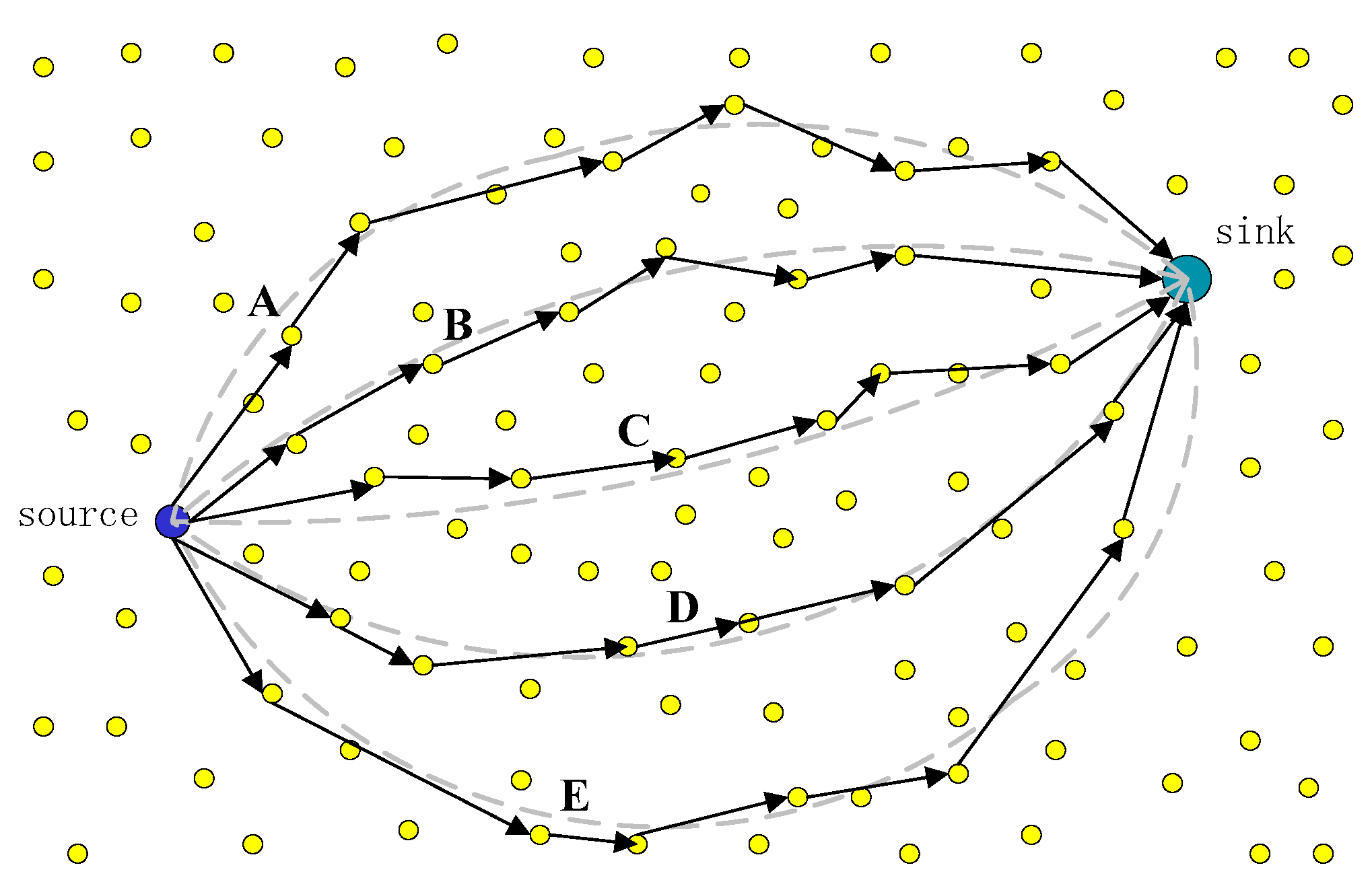
Since the length of each multipath is different, the optimal transmission distance of each hop calculated is also different. That is to say, the node with longer path length has longer transmission distance per hop, while the node with shorter path has shorter transmission distance per hop [
18]. Five paths are shown in
Figure 2. The longest two paths have a large transmission distance per hop, while the middle one has the smallest transmission distance per hop. However, they have the same number of hops, so the transmission delay is the same.
4.1. Path Generation
Some studies have applied B-spline algorithm to wireless networks. B-spline curves can be generated by parameters of any control point (≥ 2), and the path length of B-spline can be calculated by function integral. It has low computational complexity and good controllability.
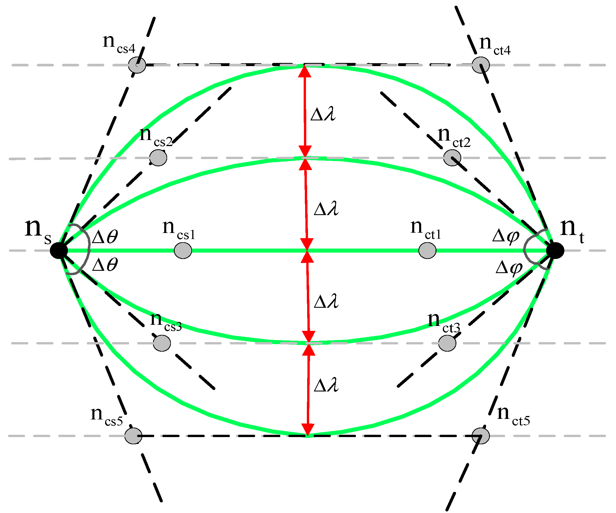
As shown in
Figure 3, A B-spline curve can be divided into three parts: spreading, parallel, and converging.
and
represent the source node and sink node, respectively. Arc
is controlled by points
,
,
,
. Arc
is controlled by points
,
,
,
. Arc
is controlled by points
,
,
,
.
The specific calculation is shown in the following Equation (20), which varies from 0 to 1. Note that the abscissa and ordinate coordinates in the formula are calculated separately, and the coordinate
of
is calculated by the following formula:
where
is the coordinate of node
is the expansion angle.
denotes the expansion distance. It can be calculated by the following formula:
where
and
are based on point
symmetry.
and
are based on point
symmetry. It can be calculated by the following formula:
In fact, only four vertices , , , and this curve can be determined. The determination of can be determined by two parameters. The first is the angle , and the second is the length of the line from to m. Multiple paths can be formed by setting different angles and the length of line segments to .
Assuming that
path are generated,
denotes the divergence angle of the
-th path.
denotes the maximum distance between the path
and the midline.
denotes the maximum distance from the middle line of the
-th path. Then
can be calculated by the following formula:
where
denotes the expansion angle, as shown in
Figure 4. In order to distribute multipath as evenly as possible in space. The deviation angle between adjacent paths is set to the same value. In order to prevent interference between paths, the distance between adjacent paths is set to
as the maximum transmission distance
.
Therefore, routing can be established by three parameters, i.e.,
,
,
adjusts the density between paths to specify control points. By specifying the maximum expansion angle
, then
can be calculated by the following formula:
4.2. Direction Control Algorithm
The path is controlled by the expansion angle, and the expansion angle is determined by the path length. The direction control algorithm consists of two parts: calculating the length of the curve and calculating the expansion angle.
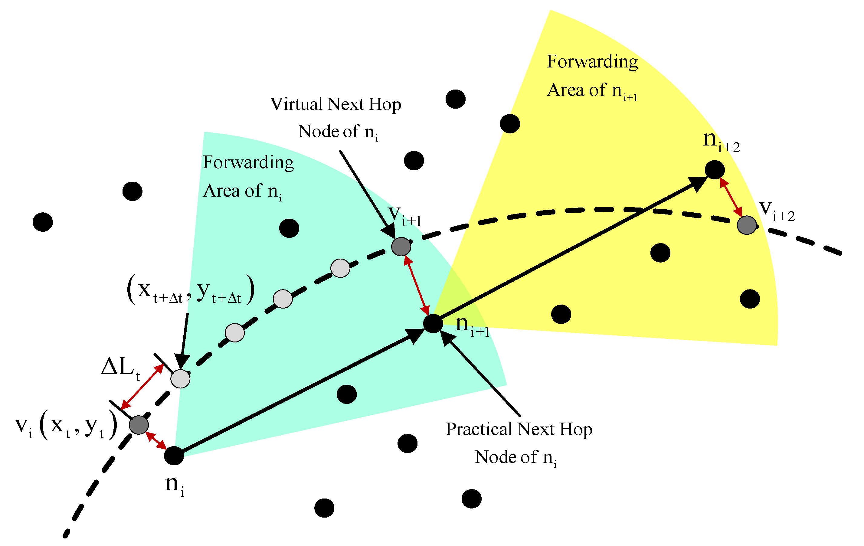
As shown in
Figure 5,
represents the current node,
represents the next hop node.
and
represent virtual nodes of
and
, respectively.
is the ideal next hop node of
node. The nearest node at this location is
, so
is chosen as the next hop node.
represents the coordinates of
,
represents
path increment.
denotes the next node of the spline curve. Then
can be calculated by the following formula:
Cumulative, then the formula of the total length of the path can be calculated by the following formula:
where the smaller the value of
, the closer the length of path calculation is to the length of ideal curve of B-spline formula. In practice, the curve length
is calculated by self-defining integral function.
Given
,
can be calculated by Algorithm 1, and
can be calculated by Equation (24):
| Algorithm 1. Get Spreading Angle (, ). |
| Input: is a small increment of ; is specified path length; |
| Output: |
| 1. = 0; |
| 2. =GetLength(,); |
| 3. while do |
| 4. ; |
| 5. =GetLength(,); |
| 6. end while |
| 7. return |
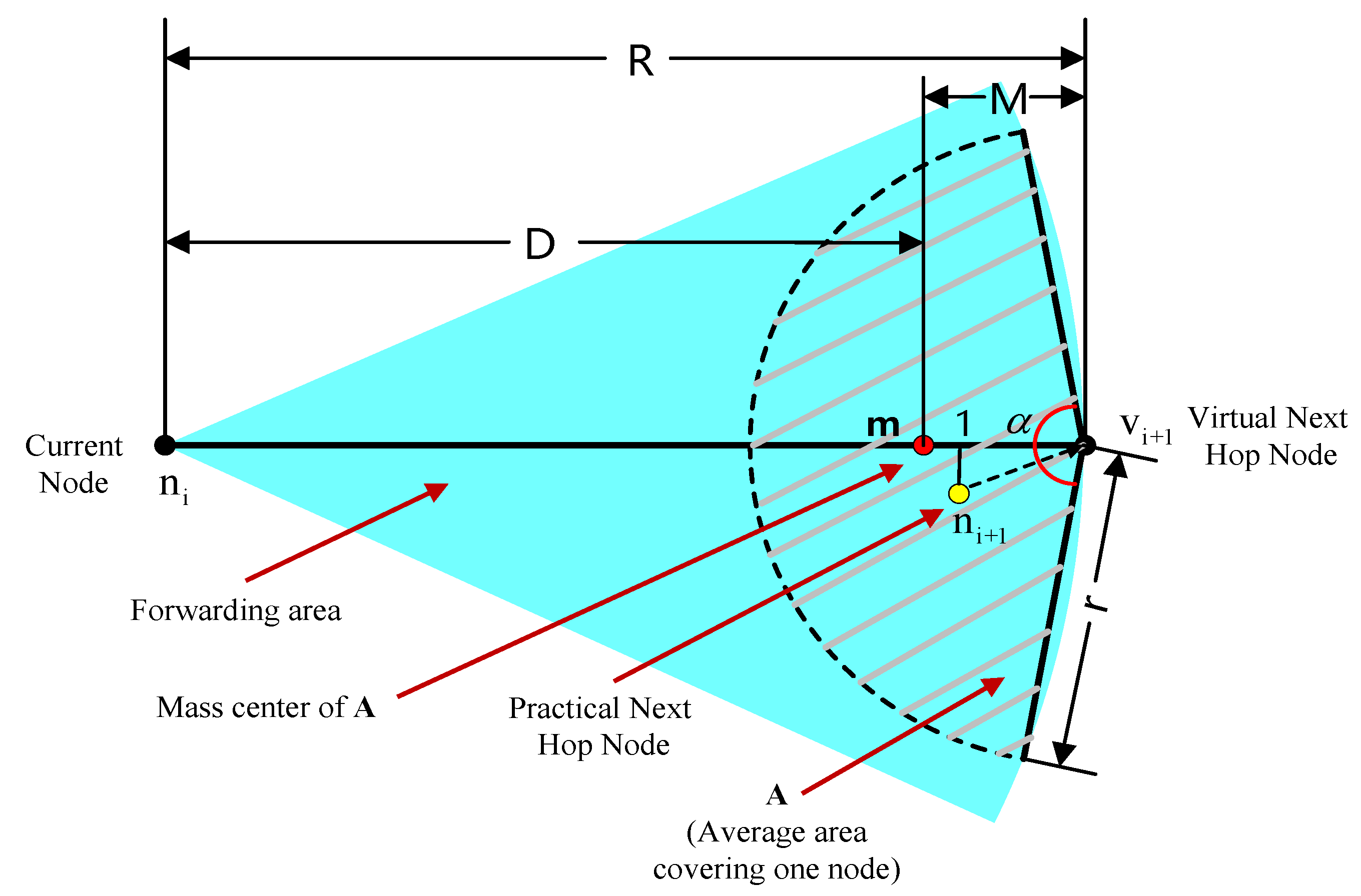
4.3. Error Correction Calculation
In most cases, the next hop node is closer than the virtual node. As the node forwards, this error accumulates. Therefore, a correction factor
is introduced to improve the actual transmission distance per hop and eliminate the error [
19]. In
Figure 6,
is the ideal next hop node of
node,
actually chooses the next hop node as
node. m is the center of gravity of the sector region with
as the center and r as the radius. From a statistical point of view, the actual selection of the next hop node is close to m point. In order to calculate the position of m, we need to calculate the center of gravity of the sector area. We need to determine the size of the sector area A and the center position
. A is set here as 1/2 of the average area of the nodes. When A and
are given, then r and
can be calculated according to the following formula:
If
, the formula for calculating the correction factor is as follows:
5. Implementation of Multimedia Independent Multipath Routing Algorithms
When multiple source nodes send data to the sink node at the same time, it poses a greater challenge to the construction of independent multipath routing. During the transmission process, some source nodes may exit or join dynamically. In order to make better use of the path resources, the source nodes need to readjust the path. In this paper, the idea of software definition is applied to centralize programming and control the multi-path routing of multiple source nodes through sink nodes, so as to realize the multi-source and multi-path coordination algorithm [
20,
21]. There are three source nodes and one sink node in the model. Each source node sends data to sink through four paths.
Considering that sink nodes are located in the center of the sensor network and multiple source nodes send data at the same time, the following issues need to be considered.
- ①
How do source nodes distribute their paths when the distribution of source nodes is not uniform around the sink nodes;
- ②
How to distribute paths when the weights of source nodes are different;
How to dynamically adjust the existing multipath routing after the source node joins and exits dynamically.
5.1. Process Description
Message and package structure tables are shown in
Table 2. Packet content includes package type, serial number, source node and target node.
5.1.1. Source Application Process
①After the initialization of the source node is finished, the RREQ packet is sent by setting self-interrupt trigger. In addition to the initialization phase, the network also allows nodes to send applications when it is running normally.
②All source nodes initialize RREQ packages. The fields in the packages include unit traffic, priority and coordinates of Source, which are sent by the shortest radial sink.
③After receiving RREQ packets, the sink is inserted into the source node queue from large to small according to the angle of the source relative to the sink. Set a self-interrupt because there are multiple source nodes. The interrupt time ensures that all node requests are processed only after RREQ messages have been received from all source nodes.
④The sink processes the source node queue, calculates the node weight according to a certain algorithm, assigns angles to each source node in the queue according to the weight ratio, and then sends RACK packets to all source nodes in turn.
⑤After all sources receive RACK packets, they start sending data.
5.1.2. Source Sends Data Flow
①Nodes begin to send data according to the starting and ending angles of applications, and the angle range applied by nodes is different in size because of different weights [
22].
②The number of paths to be sent is specified according to the traffic of the node (the number of paths to be selected according to the traffic and priority of the node, such as 200,000 paths can be considered).
③According to B-spline curve algorithm, multi-radial sink sends data packets.
5.1.3. Source Cancels the Process
①When the source node does not want to send any more data, it sends a DATA_CANCEL message to the sink node.
②When the sink node receives it, it is removed from the source node queue. The weight and allocation angle of each source node are recalculated, and RACK packets are sent to all source nodes.
③Step 4 and step 5 of enter the source application process.
5.2. Algorithmic Implementation Details
5.2.1. Sink End Angle Allocation Algorithms
In order to reduce the interference of wireless signals, the receiving angle range is allocated to each node according to the weight of source nodes, which makes the paths between nodes independent. First, we need to calculate the weight of each source node, the weight = traffic × priority. Then, the angle range that nodes can allocate is equal to node weight/all node weight and × 360. The formula is as follows:
where
is the priority of the
th node,
is the traffic of the
th node,
is the weight of the
th node,
is the sum of all node weights,
is the angle range allocated by the
th node.
5.2.2. The Choice of the Order of Angle Distribution
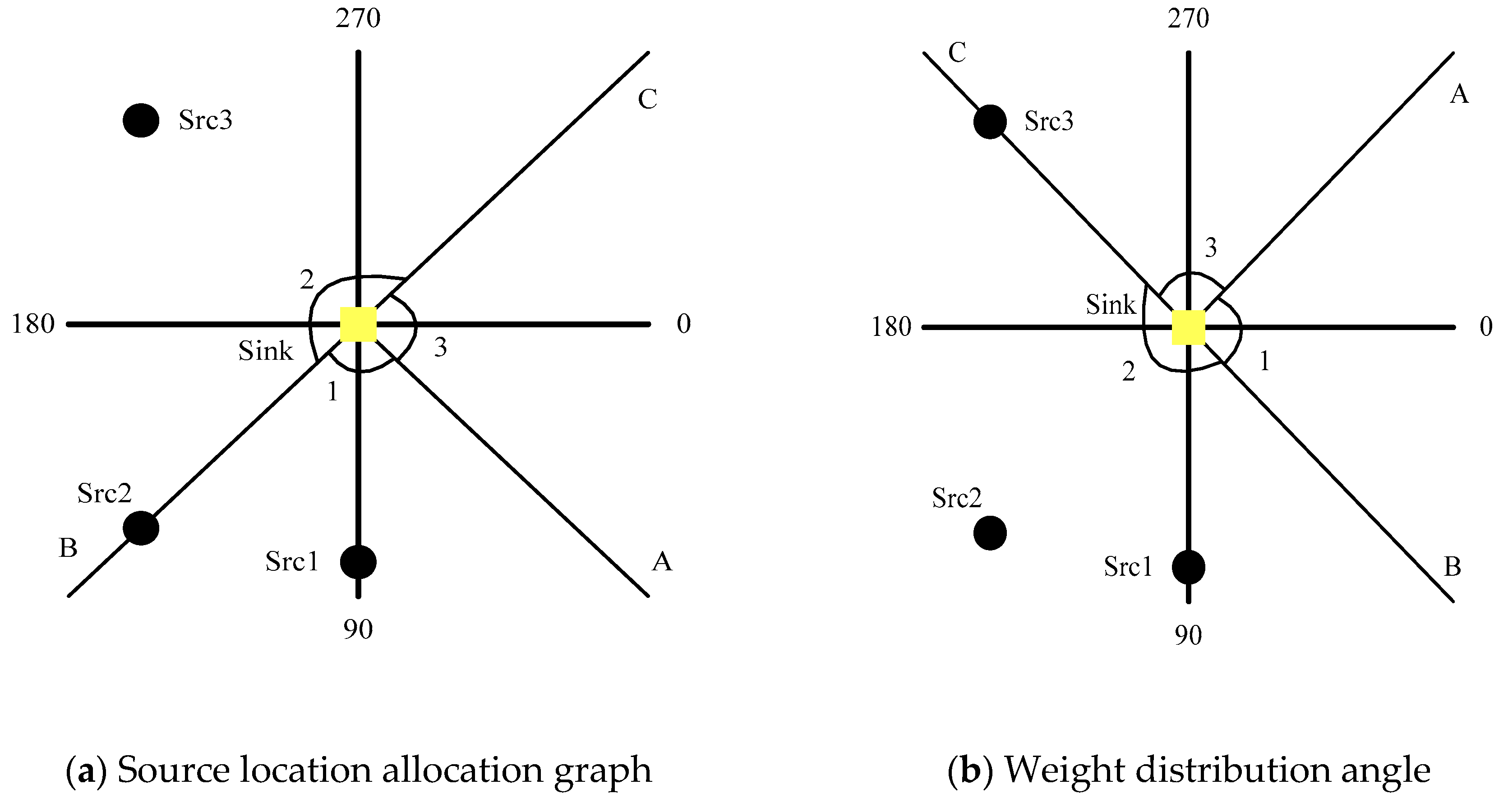
If the distribution of source nodes is not uniform, the angles assigned may vary in size. In order to balance the load, the paths need to be evenly distributed around sink nodes, so the order of angle allocation needs to be considered. The definition of coordinate system is that the angle of the horizontal line on the right side of the node is 0, clockwise from small to large. Consider the following scenarios: one sink, three sources, namely Src1, Src2, Src3. Assume that the weights of Src1 and Src3 are 1 and that of Src2 is 2. Then there are two considerations for the allocation scheme.
①Location allocation based on the source.
The first allocation scheme is based on the location allocation of the source. The smaller the angle of Source relative to the sink, the earlier the allocation. Since the angle of Src1 is at 090, the angle range that should be allocated according to the weight calculation is as follows:
With Src1 as the center, the distribution angle of Src1 is 45°–135°. The weight of Src2 is 2 and its angle range is 180. Then the angle of distribution is followed by Src1, i.e., 135°–315°. Src3 ranges from 315° to 45°, as shown in
Figure 7a. Although Src1 is located in the middle of its angle range, Src2 is located on one side of its angle range, while Src3 is completely out of its angle range.
②Distribution begins with the node with the largest weight.
Considering that the larger the weight of the node, the larger the angle range of the allocation, in order to take care of the node with the largest weight, the node with the largest weight is assigned priority here. As shown in
Figure 7b. The distribution range of Src2 is from 45° to 225° and occupies the range of Src1. The range of Src1 is from A to B, ranging from −45° to 45°.
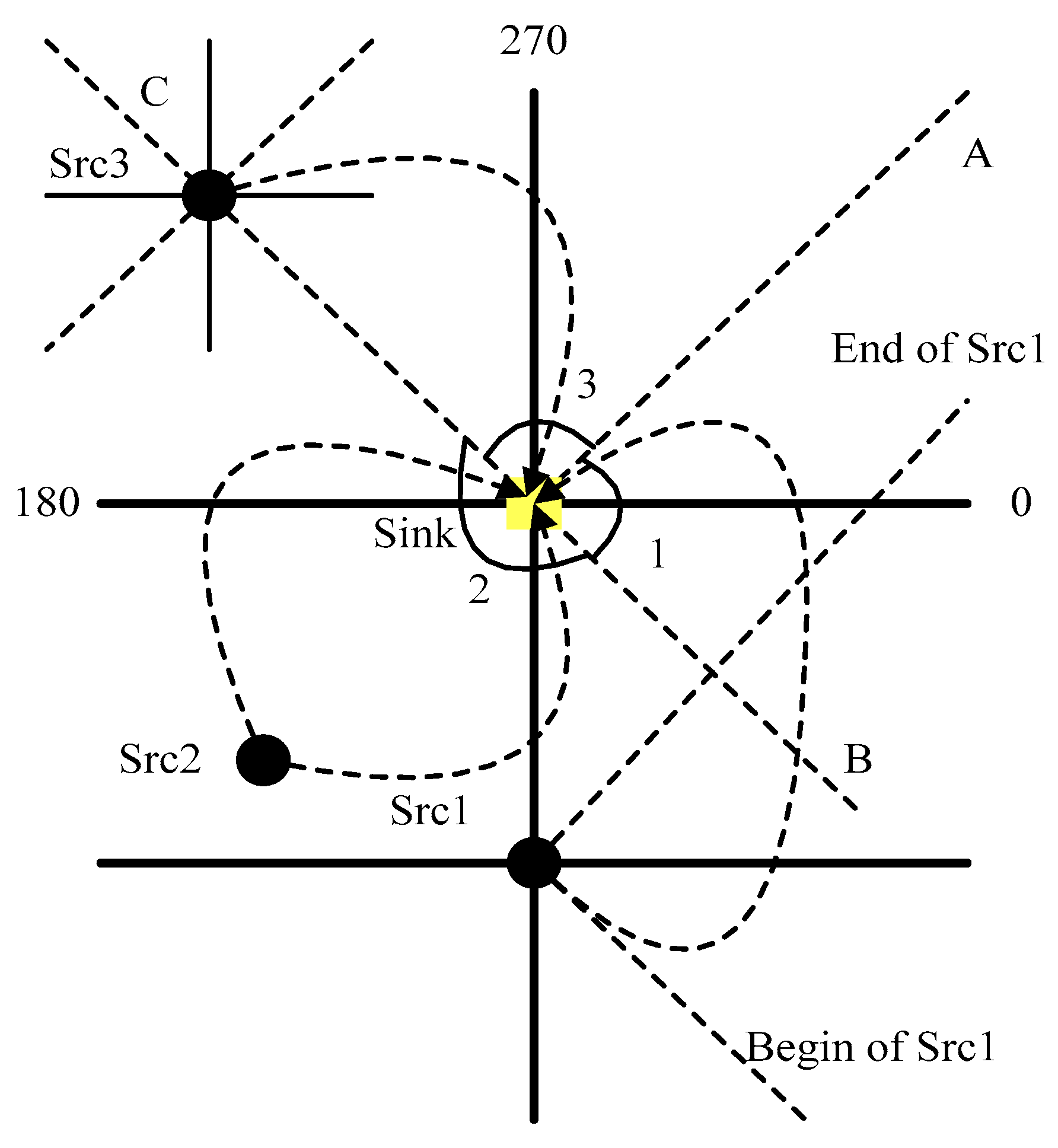
5.2.3. Selection of the Sending Angle Range at the Source End
For the source, because the nodes are not located in the middle of the allocated angle range, the transmission angle range of the path should be considered. In order to keep the sending routes between source nodes from crossing, the range of the source sending angle needs to be determined according to the receiving angle allocated by the sink terminal. The formula is as follows:
As shown in
Figure 4,
Figure 5,
Figure 6,
Figure 7 and
Figure 8, for the sink, Src1 is located at 90 degree angle of the sink, and the range of angle allocated is (−45° to 45°), while the relative angle offset is (−135° to 45°). According to Equation (33), that is, the sink is at a 270 degree angle of SRC 1. According to Equation (33),
, that is, the sink is at 270 degrees of Scr1. The starting angle of Src1 is 270°−(−135°) = 405°. The end angle is 270° − (−45°) = 315°. The transmission curve is shown in
Figure 8.
5.2.4. Determination of the Number of Paths at Source end and the Angle between Paths
If different source nodes install different camera resolutions, so the amount of data to be transmitted per unit time is different. In order to balance the paths, the size of each path packet is limited to no more than
at a time. This requires
routes to be sent, of which
represents traffic.
represents the angle of interval between each path. In the edge zone,
of 1/2 is set aside as the interval, and the formula for calculating the interval angle between paths is as follows:
For example, Src1 needs 600 KB of traffic and 200 KB of packet size in a certain period of time. Assuming that each path can fully meet the delay requirement, the required number of paths is 600k/200k = 3. . According to the formula, the angles of the three paths are 390 degrees, 360 degrees, and 330 degrees, respectively.
6. Simulation Verification
In order to verify the proposed independent multi-path routing algorithm for networked multimedia, a simulation experiment is designed. The simulation scenario is 500 m × 900 m with 2000 nodes, and the average area of each node is 225 square meters. It is assumed that both the receiving end node and the ordinary sensor node are stationary. The sensor application module consists of a fixed bit rate data source, which generates multimedia traffic with QoS requirements. We use IEEE 802.11b DCF as the MAC layer protocol. All nodes know their geographic location by means of positioning system. All nodes know the geographic location of other nodes within their transmission radius and call these other nodes neighbors or one-hop reachable nodes.
6.1. Delay and Energy Model Verification
is set to 0.01 and five paths are set.
Table 3 is the actual simulation results,
is the end-to-end delay,
is the path length,
is the actual hop number,
is the actual hop delay,
is the actual hop length. The expansion angle increases from 40 to 120 degrees. With the increase,
and
increased correspondingly.
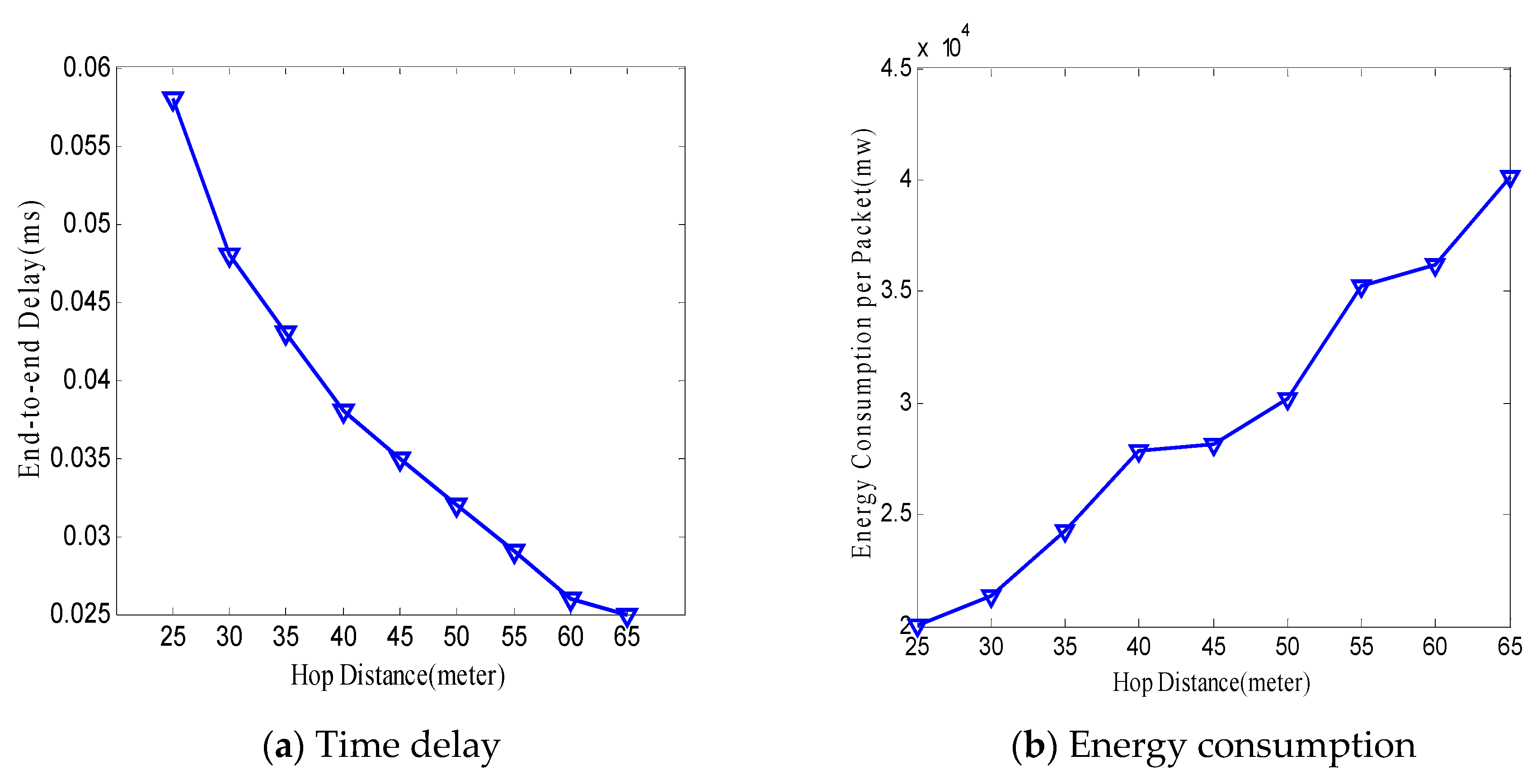
The average delay per hop is 0.0026 s, which is consistent with the theoretical calculation. It is noted that the actual distance per hop is 53 m, which is smaller than the 60 m set. Since the actual distance per hop is smaller than the corresponding virtual distance per hop. In order to verify the impact on energy consumption and time delay, the simulation is set from 25 m to 60 m, and the results are shown in
Figure 9. Energy consumption and time delay show a compromise. The smaller
is, the larger the delay and the lower the energy consumption are. Under the condition of meeting the demand of time delay, the smaller
is, the lower energy consumption is.
6.2. Performance Parameter
Set to 0.03 s, and the number of paths is 5. There are three schemes: pure spline multipath, delay multipath and delay error correction multipath.
①Pure spline multipath: no delay requirement. The results are shown in
Table 4. The path delay changes from 0.027 s to 0.039 s. Two of the five roads cannot meet the delay requirements. On the other hand, without energy consumption control, the maximum transmission distance is always used for each hop, and the average energy consumption is high. This scheme cannot meet the demand of time delay and has high energy consumption.
It is observed that the transmission distance is inversely proportional to the transmission distance, and the actual transmission distance per hop is corrected. Higher accuracy is obtained. End-to-end delay is guaranteed and more energy is saved. As shown in
Table 6.
6.3. Performance Parameter
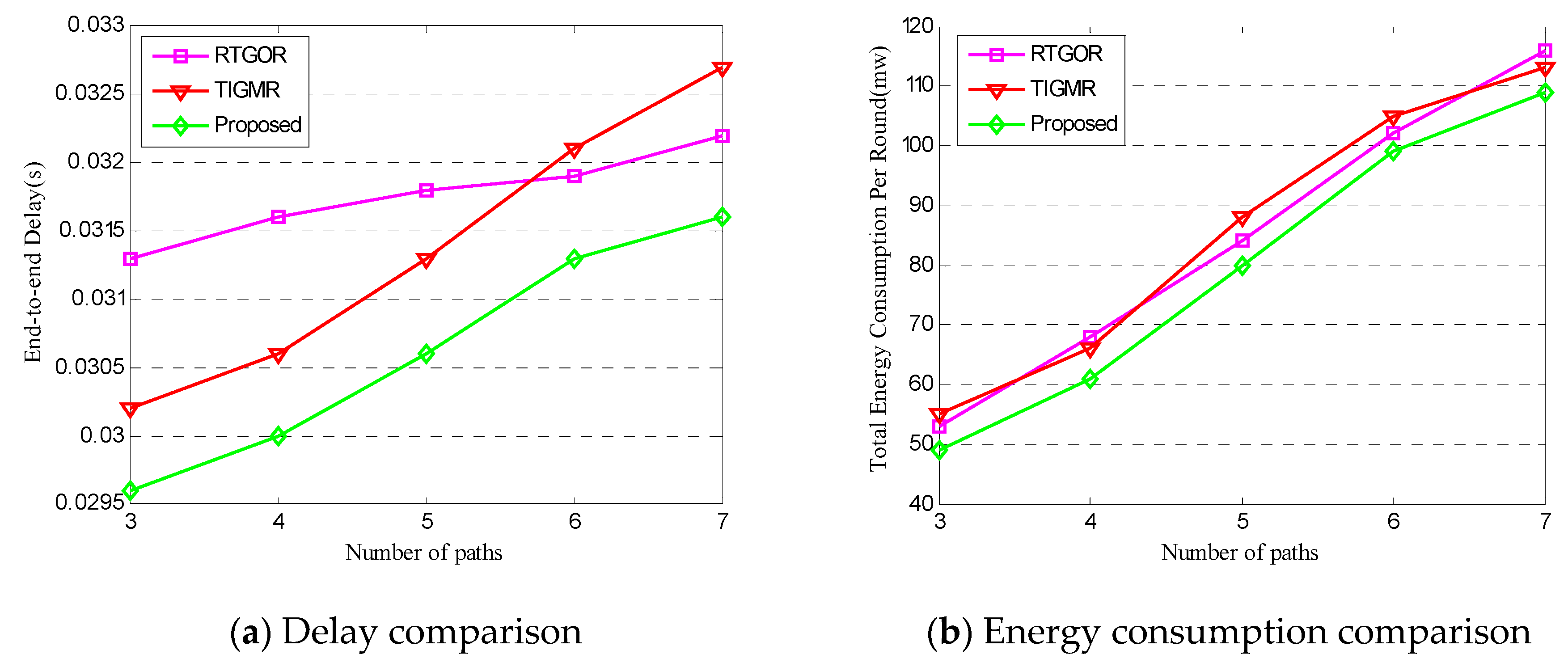
Most of the existing multimedia independent multipath routing algorithms are based on the maximum transmission distance per hop, without considering the balance of delay and energy consumption. Therefore, it is necessary to study new delay and energy balance routing algorithms. In this paper, a new algorithm is proposed. When multiple source nodes send data to sink nodes through multiple paths at the same time, in order to avoid interference caused by path crossover, Multiple source nodes coordinate transmission paths to avoid interference. We compare the algorithm with RTGOR algorithm [
11] and TIGMR algorithm [
12], and compare the following parameters:
①Average end-to-end delay, including various delays, such as queuing, retransmitting and transmission delays.
②Energy consumption E (mw) per round: Total energy consumption of 60 packets in all routes:
A large number of simulations have been done to change
from 0.02 s to 0.04 s.
Figure 10a shows the time-delay comparison.
Figure 10b shows the energy consumption comparison of several routing algorithms. Since the time-delay is not considered in RTGOR algorithm and TIGMR algorithm, the energy consumption of the proposed algorithm is higher. The energy consumption of the proposed algorithm is better than that of the algorithm in RTGOR algorithm and TIGMR algorithm, and its energy consumption increases with the increase of
. It is necessary to set
according to the actual situation in order to give full play to the advantages of the algorithm. When the number of paths increases from three to seven, because of the interference between paths and various network attacks, the energy consumption and delay of the three algorithms increase, because the path of the TIGMR algorithm is denser than other algorithms, so the delay is lower. The best performance of this algorithm is to satisfy the requirement of QoS delay. The interference between the path and various network attacks is avoided to the greatest extent, and the energy consumption is the lowest.
7. Concluding Remarks
IoT is an extension of the Internet, which extends the scope of interconnection to anything and everything. The new generation of information and network technology with IoT and software defined networks as the core is the hotspot of current computer network research.
This paper studies the multi-media independent multi-path routing algorithm. Using the idea of software definition, a multi-source multi-path routing algorithm is proposed. Through sink node centralized programming control source node routing, one can dynamically coordinate the multipath routing of each source node according to the change of the source node. The model is deeply analyzed, and the anti-attack technology based on the hidden communication model of the IoT is emphatically studied. In the node hidden communication model, the anonymity of forwarding network, sender and receiver determines the anonymity of the model. In the aspect of multimedia independent multipath routing, most of the existing multimedia independent multipath routing algorithms are based on the maximum transmission distance per hop, without considering the balance of the delay and energy consumption.
There have been many studies on multipath routing in wireless sensor networks. In the research of multipath routing, the mobility of nodes, cross-layer design, duty cycle of nodes, and data fusion need to be further studied. In addition, the energy consumption of network nodes will be further balanced in the future, ensuring the effectiveness and security of routing nodes.


