
A 3D Lidar SLAM System Based on Semantic Segmentation for Rubber-Tapping Robot


Abstract
:1. Introduction
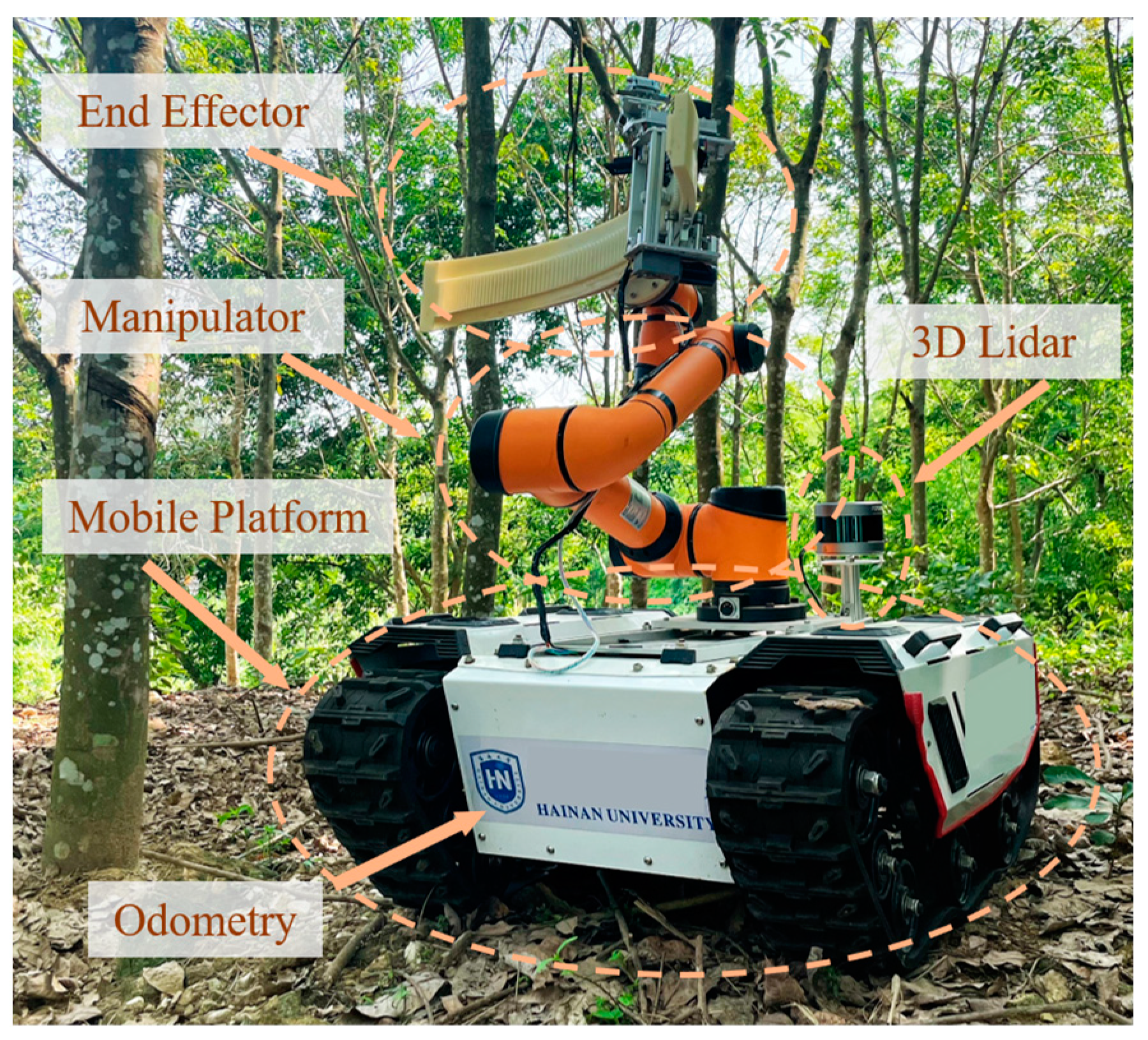
2. System Overview
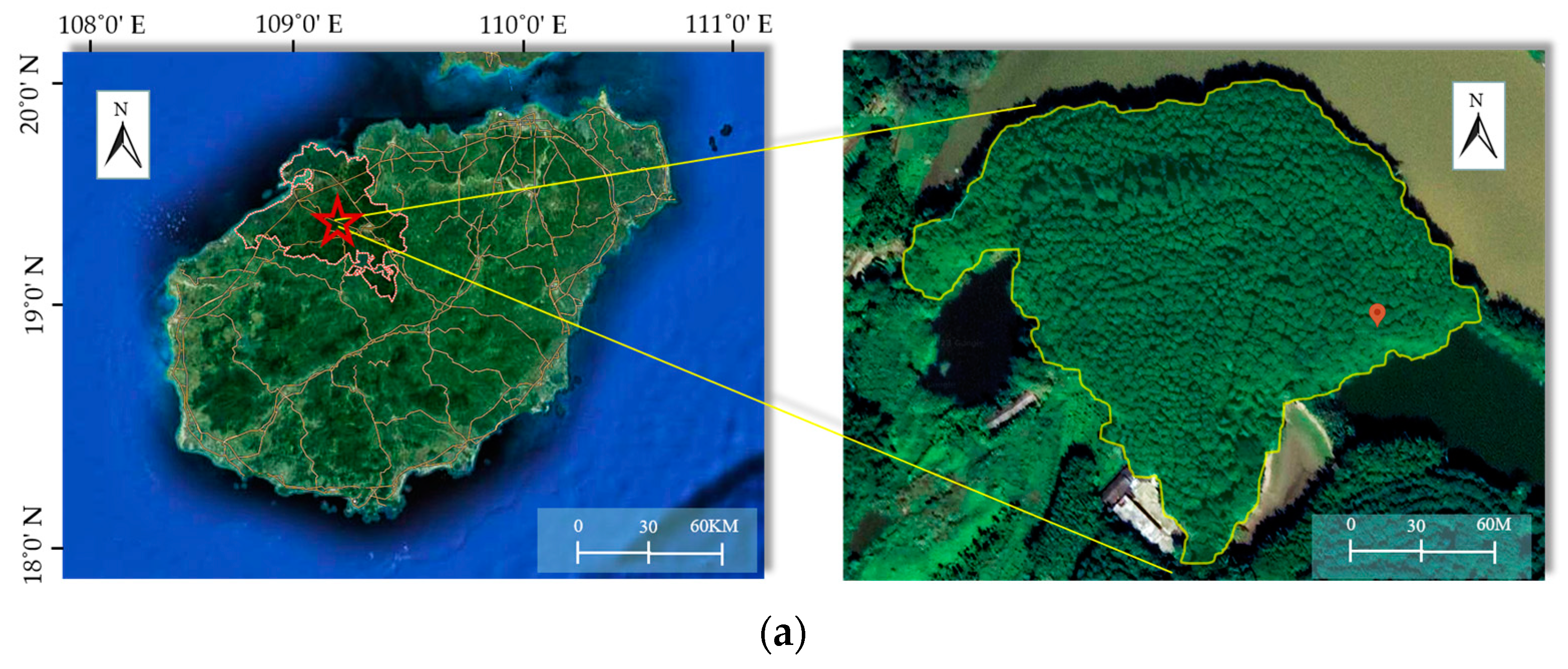
3. Materials and Methods
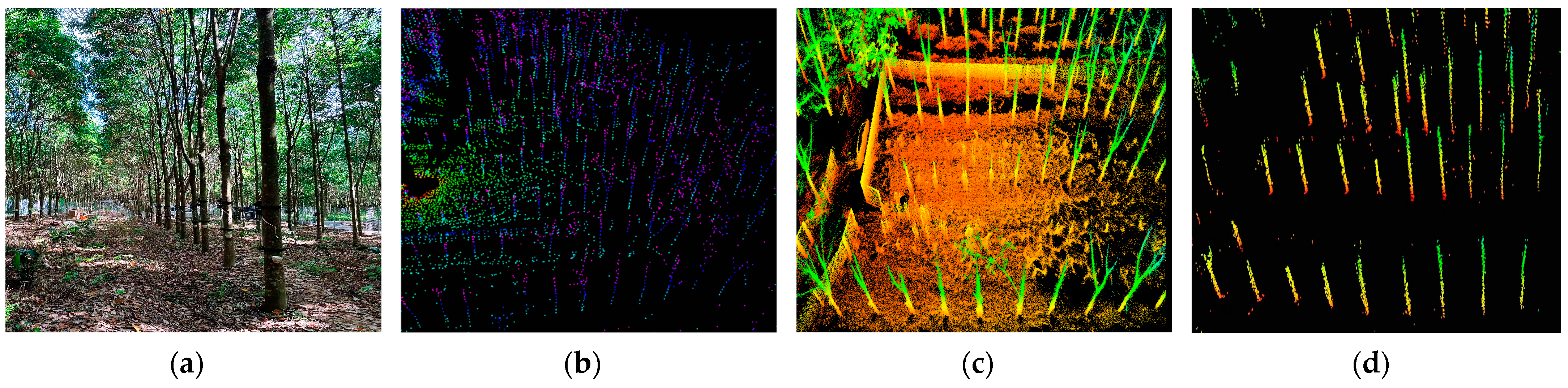
3.1. Point Cloud Processing
- (a)
- Point Cloud Filtering
- (b)
- Storage Structure
- (c)
- Range Image Construction
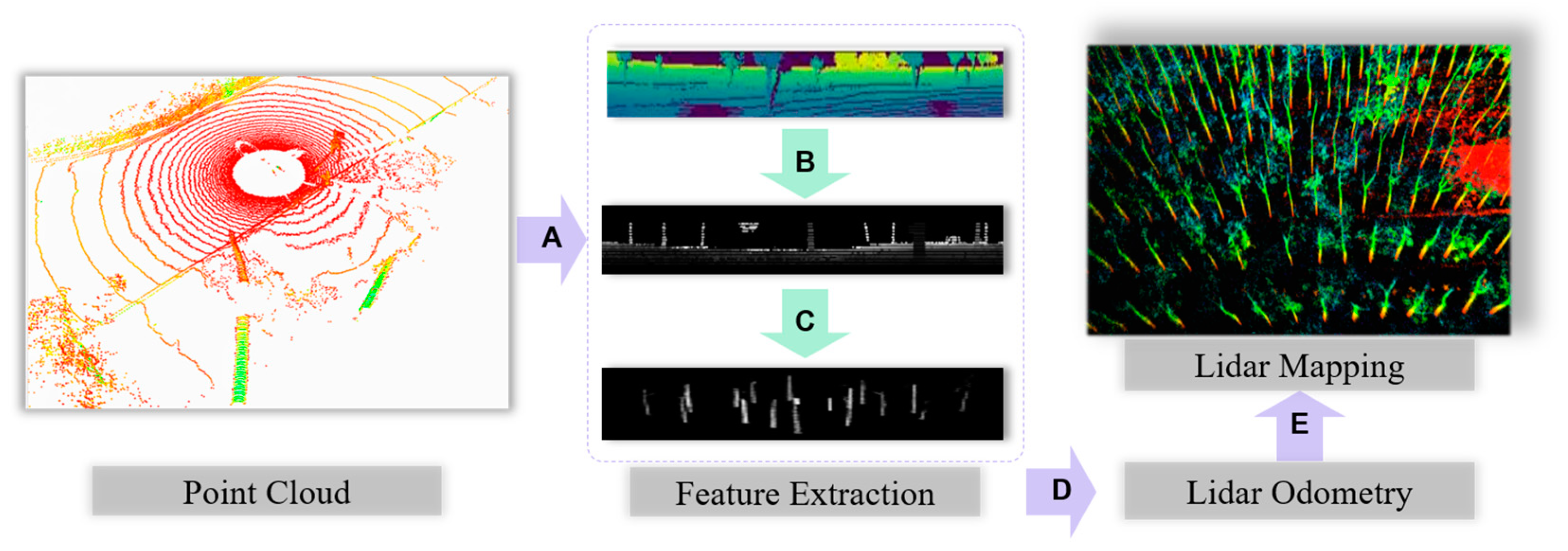
3.2. Feature Extraction
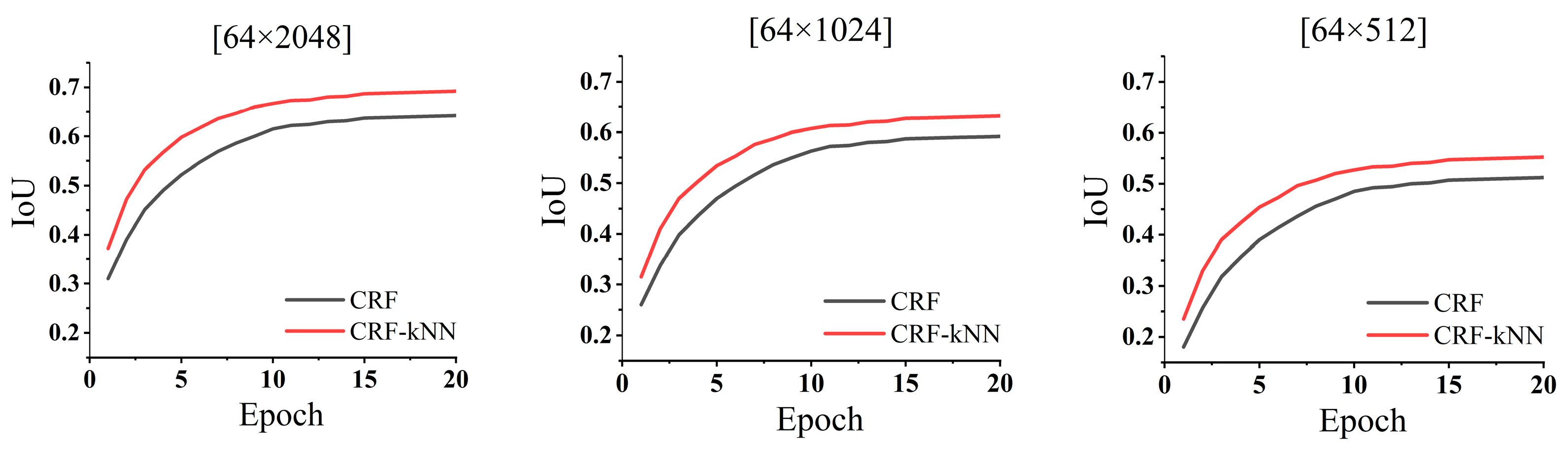
3.2.1. Semantic Network Training
3.2.2. Semantic Feature Clustering
| Algorithm 1: Tree-trunk Point Cloud Segmentation Based on Viterbi Algorithm |
| Input: Semantic range image of size ; label index ; minimum number of points clouds ; and minimum height of trees . |
| Output: Tree point clouds with ordered index |
| 1: If at the beginning of a sweep do |
| 2: |
| 3: end if |
| 4: For each label index do |
| 5: If then |
| 6: Create a new tree structure S |
| 7: For each do |
| 8: For each do |
| 9: If then |
| 10: Create a new container Q, add to Q.points |
| 11: end if |
| 12: end for |
| 13: If Q.points can fit into a unique circle C then |
| 14: Create a new node V |
| 15: V.data = C |
| 16: V.index = |
| 17: Add V to S |
| 18: end if |
| 19: end for |
| 20: If S.size > then |
| 21: Add S to |
| 22: end if |
| 23: end if |
| 24: end for |
| 25: return |
3.3. Lidar Odometry
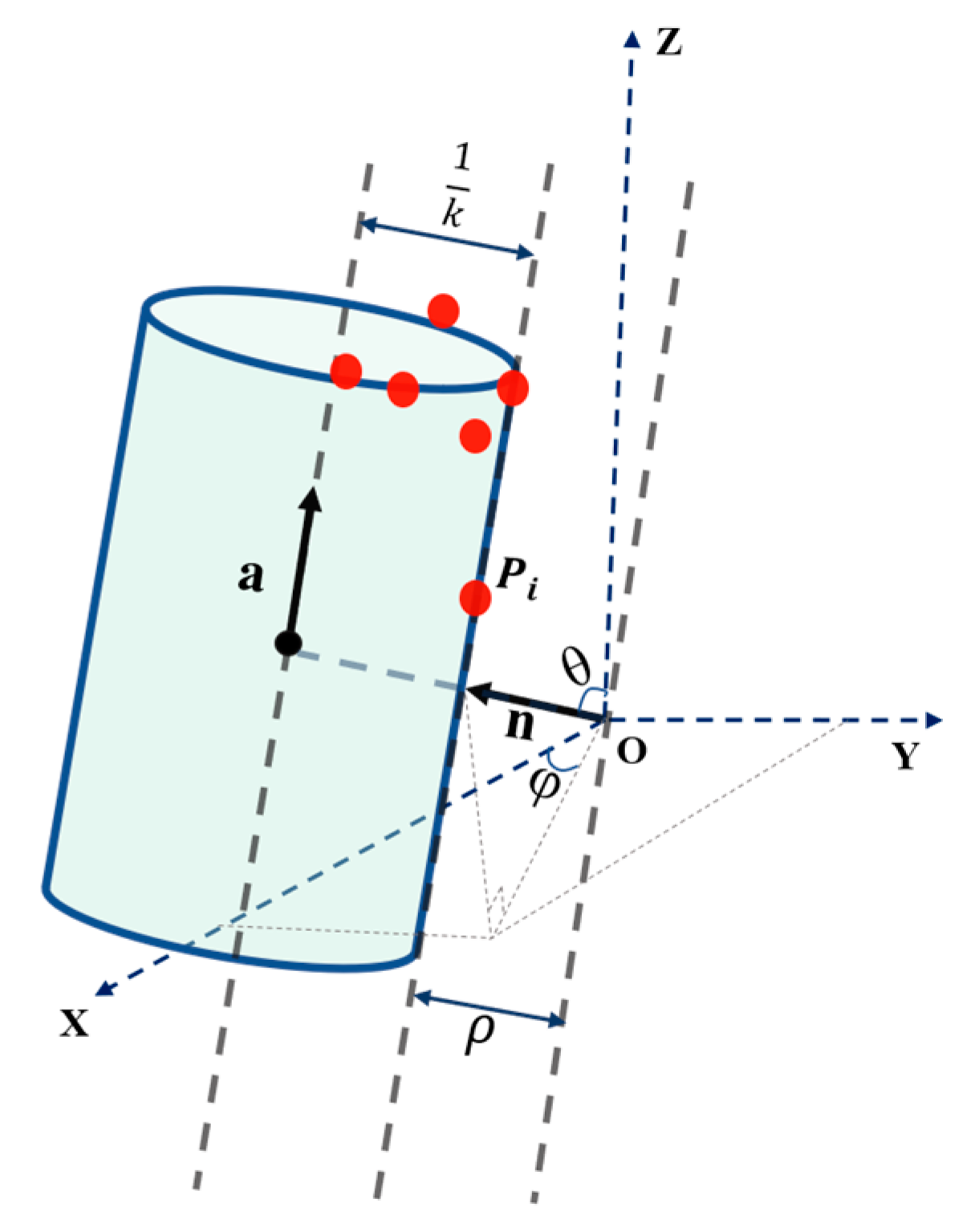
3.3.1. Semantic Feature Fitting
3.3.2. Feature Point Correspondence and Motion Estimation
3.4. Lidar Mapping
4. Results
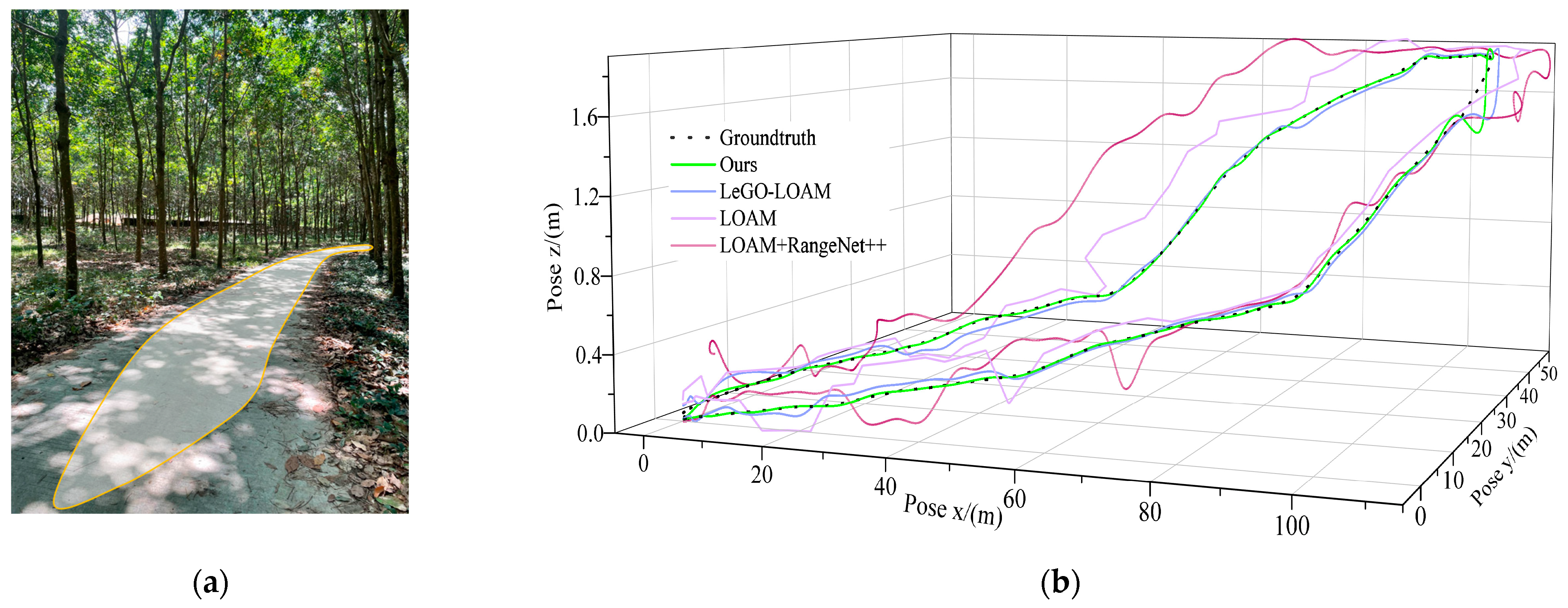
- Comparison of map construction results using different SLAM algorithms.
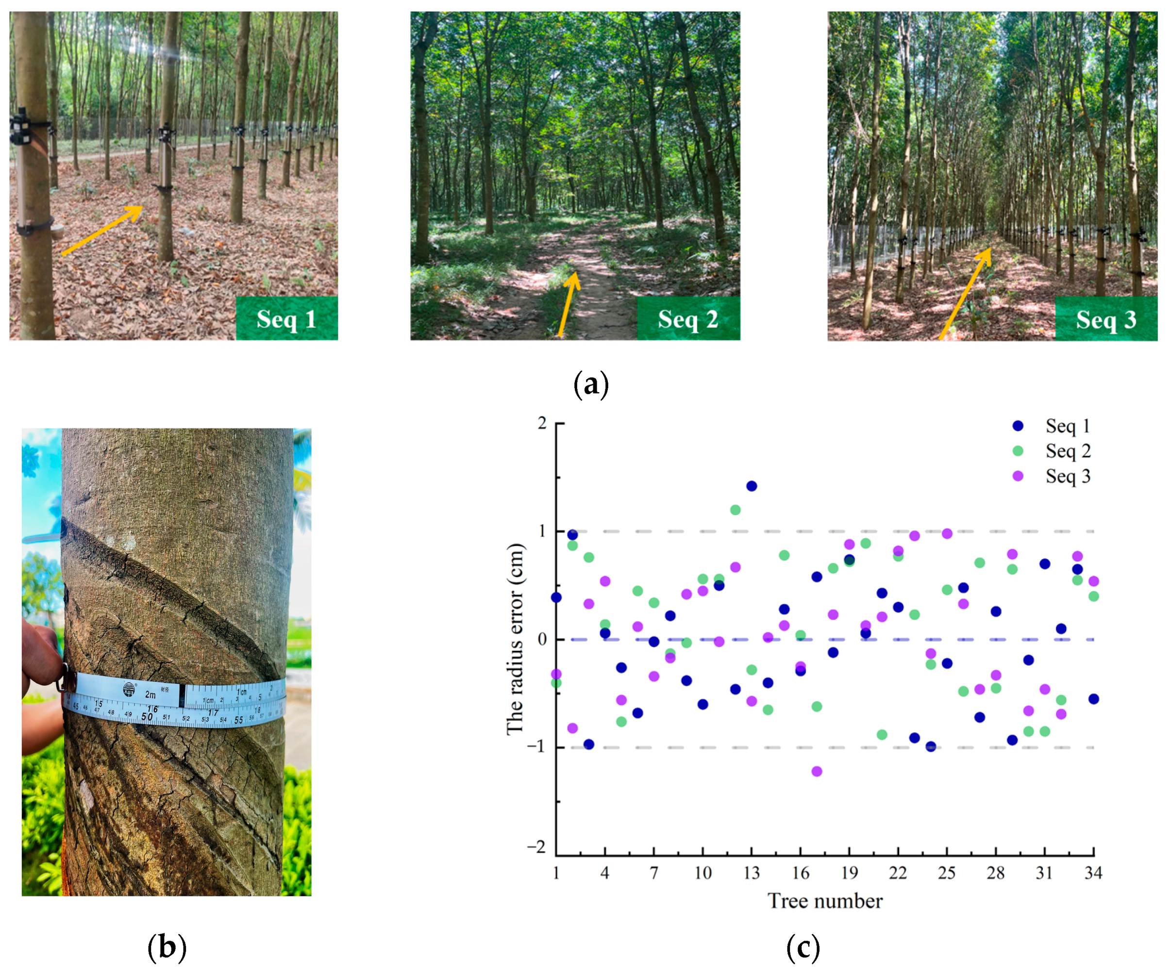
- Estimation error of rubber tree DBH and location error.
- Running time and memory consumption of global map construction.
4.1. Mapping Performance
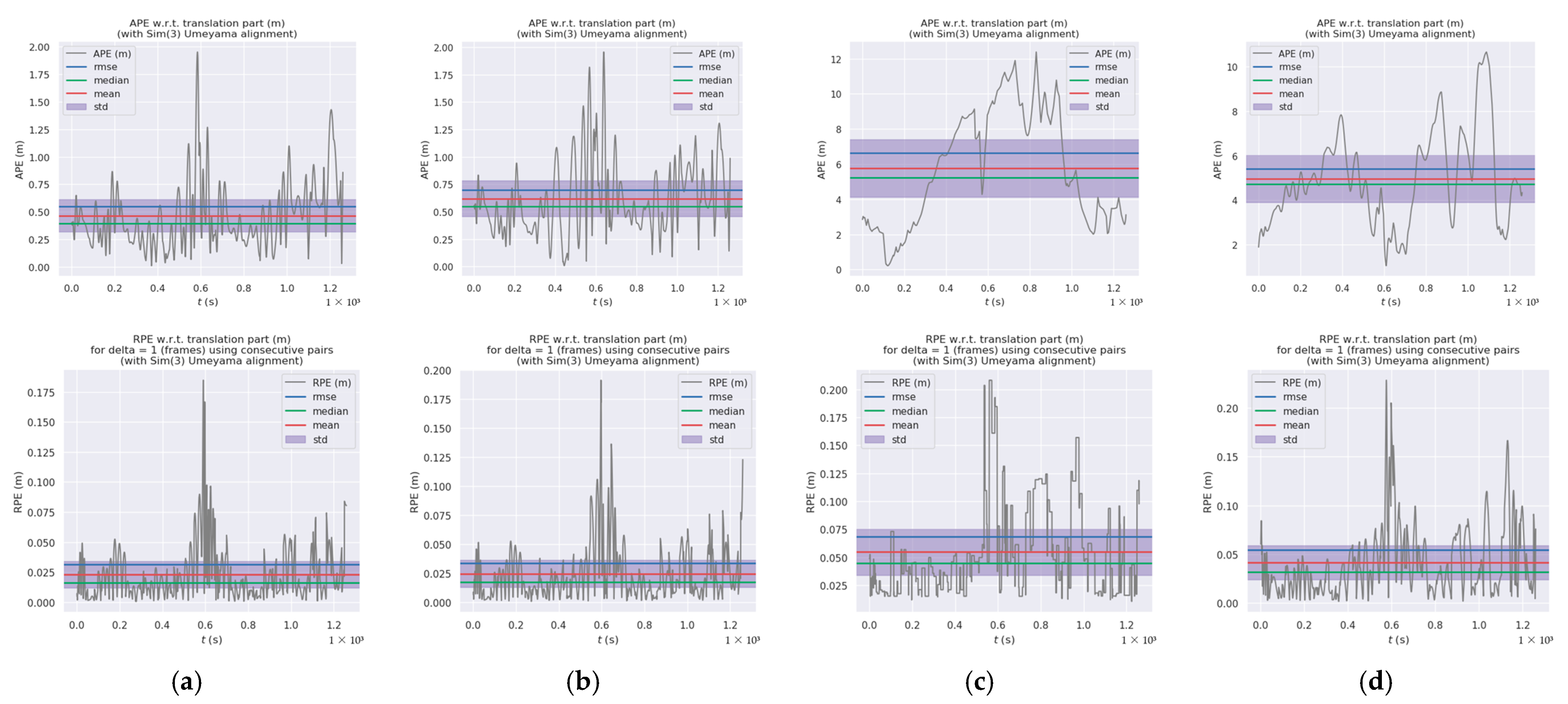
4.2. Localization Performance Accuracy
4.3. Experiment on Efficiency
5. Discussion
6. Conclusions
Author Contributions
Funding
Data Availability Statement
Acknowledgments
Conflicts of Interest
References
- Zhang, C.L.; Yong, L.Y.; Chen, Y.; Zhang, S.L.; Ge, L.Z.; Wang, S.; Li, W. A Rubber-Tapping Robot Forest Navigation and Information Collection System Based on 2D LiDAR and a Gyroscope. Sensors 2019, 19, 2136. [Google Scholar] [CrossRef] [PubMed]
- Palieri, M.; Morrell, B.; Thakur, A.; Ebadi, K.; Nash, J.; Chatterjee, A.; Kanellakis, C.; Carlone, L.; Guaragnella, C.; Agha-Mohammadi, A.A. LOCUS: A Multi-Sensor Lidar-Centric Solution for High-Precision Odometry and 3D Mapping in Real-Time. IEEE Robot. Autom. Lett. 2021, 6, 421–428. [Google Scholar] [CrossRef]
- Bauwens, S.; Bartholomeus, H.; Calders, K.; Lejeune, P. Forest Inventory with Terrestrial LiDAR: A Comparison of Static and Hand-Held Mobile Laser Scanning. Forests 2016, 7, 127. [Google Scholar] [CrossRef]
- Polewski, P.; Yao, W.; Cao, L.; Gao, S. Marker-free coregistration of UAV and backpack LiDAR point clouds in forested areas. Isprs J. Photogramm. Remote Sens. 2019, 147, 307–318. [Google Scholar] [CrossRef]
- Shao, J.; Zhang, W.M.; Mellado, N.; Wang, N.; Jin, S.G.; Cai, S.S.; Luo, L.; Lejemble, T.; Yan, G.J. SLAM-aided forest plot mapping combining terrestrial and mobile laser scanning. Isprs J. Photogramm. Remote Sens. 2020, 163, 214–230. [Google Scholar] [CrossRef]
- Yang, H.; Sun, Z.J.; Liu, J.X.; Zhang, Z.F.; Zhang, X.R. The Development of Rubber Tapping Machines in Intelligent Agriculture: A Review. Appl. Sci. 2022, 12, 9304. [Google Scholar] [CrossRef]
- Zhou, Y.; Tuzel, O. VoxelNet: End-to-End Learning for Point Cloud Based 3D Object Detection. In Proceedings of the 31st IEEE/CVF Conference on Computer Vision and Pattern Recognition (CVPR), Salt Lake City, UT, USA, 18–23 June 2018; pp. 4490–4499. [Google Scholar]
- Galceran, E.; Carreras, M. A survey on coverage path planning for robotics. Robot. Auton. Syst. 2013, 61, 1258–1276. [Google Scholar] [CrossRef]
- Jones, E.S.; Soatto, S. Visual-inertial navigation, mapping and localization: A scalable real-time causal approach. Int. J. Robot. Res. 2011, 30, 407–430. [Google Scholar] [CrossRef]
- Labbe, M.; Michaud, F. RTAB-Map as an open-source lidar and visual simultaneous localization and mapping library for large-scale and long-term online operation. J. Field Robot. 2019, 36, 416–446. [Google Scholar] [CrossRef]
- Hess, W.; Kohler, D.; Rapp, H.; Andor, D. Real-Time Loop Closure in 2D LIDAR SLAM. In Proceedings of the IEEE International Conference on Robotics and Automation (ICRA), Stockholm, Sweden, 16–21 May 2016; pp. 1271–1278. [Google Scholar]
- Ye, H.Y.; Chen, Y.Y.; Liu, M. Tightly Coupled 3D Lidar Inertial Odometry and Mapping. In Proceedings of the IEEE International Conference on Robotics and Automation (ICRA), Montreal, Canada, 20–24 May 2019; pp. 3144–3150. [Google Scholar]
- Weiss, U.; Biber, P. Plant detection and mapping for agricultural robots using a 3D LIDAR sensor. Robot. Auton. Syst. 2011, 59, 265–273. [Google Scholar] [CrossRef]
- Chen, S.W.; Nardari, G.V.; Lee, E.S.; Qu, C.; Liu, X.; Romero, R.A.F.; Kumar, V. SLOAM: Semantic Lidar Odometry and Mapping for Forest Inventory. IEEE Robot. Autom. Lett. 2020, 5, 612–619. [Google Scholar] [CrossRef]
- Han, S.Q.; Xi, Z.H. Dynamic Scene Semantics SLAM Based on Semantic Segmentation. IEEE Access 2020, 8, 43563–43570. [Google Scholar] [CrossRef]
- Wang, X.T.; Fan, X.N.; Shi, P.F.; Ni, J.J.; Zhou, Z.K. An Overview of Key SLAM Technologies for Underwater Scenes. Remote Sens. 2023, 15, 2496. [Google Scholar] [CrossRef]
- Debeunne, C.; Vivet, D. A Review of Visual-LiDAR Fusion based Simultaneous Localization and Mapping. Sensors 2020, 20, 2068. [Google Scholar] [CrossRef]
- Zhou, L.P.; Huang, G.Q.; Mao, Y.N.; Yu, J.C.; Wang, S.Z.; Kaess, M. PLC-LiSLAM: LiDAR SLAM With Planes, Lines, and Cylinders. IEEE Robot. Autom. Lett. 2022, 7, 7163–7170. [Google Scholar] [CrossRef]
- Zhao, Y.M.; Zhang, X.; Huang, X.M.; Soc, I.C. A Technical Survey and Evaluation of Traditional Point Cloud Clustering Methods for LiDAR Panoptic Segmentation. In Proceedings of the 18th IEEE/CVF International Conference on Computer Vision (ICCV), Montreal, Canada, 11–17 October 2021; pp. 2464–2473. [Google Scholar]
- Pierzchala, M.; Giguere, P.; Astrup, R. Mapping forests using an unmanned ground vehicle with 3D LiDAR and graph-SLAM. Comput. Electron. Agric. 2018, 145, 217–225. [Google Scholar] [CrossRef]
- Fan, Z.; Wei, J.; Zhang, R.; Zhang, W. Tree Species Classification Based on PointNet++ and Airborne Laser Survey Point Cloud Data Enhancement. Forests 2023, 14, 1246. [Google Scholar] [CrossRef]
- Wang, Z.H.; Li, S.L.; Cao, M.; Chen, H.Y.; Liu, Y.H. Pole-like Objects Mapping and Long-Term Robot Localization in Dynamic Urban Scenarios. In Proceedings of the 2021 IEEE International Conference on Robotics and Biomimetics (IEEE-Robio 2021), Sanya, China, 27–31 December 2021; pp. 998–1003. [Google Scholar] [CrossRef]
- Milioto, A.; Vizzo, I.; Chley, J.; Stachniss, C. RangeNet plus plus: Fast and Accurate LiDAR Semantic Segmentation. In Proceedings of the IEEE/RSJ International Conference on Intelligent Robots and Systems (IROS), Macau, China, 4–8 November 2019; pp. 4213–4220. [Google Scholar]
- Zhang, J.D.; Wang, W.; Qi, X.Y.; Liao, Z.W. Social and Robust Navigation for Indoor Robots Based on Object Semantic Grid and Topological Map. Appl. Sci. 2020, 10, 8991. [Google Scholar] [CrossRef]
- Zhu, J.S.; Li, Q.; Cao, R.; Sun, K.; Liu, T.; Garibaldi, J.M.; Li, Q.Q.; Liu, B.Z.; Qiu, G.P. Indoor Topological Localization Using a Visual Landmark Sequence. Remote Sens. 2019, 11, 73. [Google Scholar] [CrossRef]
- Chen, X.Y.L.; Milioto, A.; Palazzolo, E.; Giguere, P.; Behlcy, J.; Stachniss, C. SuMa plus plus: Efficient LiDAR-based Semantic SLAM. In Proceedings of the IEEE/RSJ International Conference on Intelligent Robots and Systems (IROS), Macau, China, 4–8 November 2019; pp. 4530–4537. [Google Scholar]
- Li, S.X.; Li, G.Y.; Wang, L.; Qin, Y.C. SLAM integrated mobile mapping system in complex urban environments. ISPRS J. Photogramm. Remote Sens. 2020, 166, 316–332. [Google Scholar] [CrossRef]
- Zhao, S.B.; Fang, Z.; Li, H.L.; Scherer, S. A Robust Laser-Inertial Odometry and Mapping Method for Large-Scale Highway Environments. In Proceedings of the IEEE/RSJ International Conference on Intelligent Robots and Systems (IROS), Macau, China, 4–8 November 2019; pp. 1285–1292. [Google Scholar]
- Milioto, A.; Lottes, P.; Stachniss, C. Real-time Semantic Segmentation of Crop and Weed for Precision Agriculture Robots Leveraging Background Knowledge in CNNs. In Proceedings of the IEEE International Conference on Robotics and Automation (ICRA), Brisbane, Australia, 21–25 May 2018; pp. 2229–2235. [Google Scholar]
- Lin, J.R.; Zhang, F. Loam_livox: A fast, robust, high-precision LiDAR odometry and mapping package for LiDARs of small FoV. In Proceedings of the IEEE International Conference on Robotics and Automation (ICRA), Paris, France, 31 May–15 June 2020; pp. 3126–3131. [Google Scholar]
- Zhang, J.; Singh, S. Low-drift and real-time lidar odometry and mapping. Auton. Robot. 2017, 41, 401–416. [Google Scholar] [CrossRef]
- Shan, T.X.; Englot, B. LeGO-LOAM: Lightweight and Ground-Optimized Lidar Odometry and Mapping on Variable Terrain. In Proceedings of the 25th IEEE/RSJ International Conference on Intelligent Robots and Systems (IROS), Madrid, Spain, 1–5 October 2018; pp. 4758–4765. [Google Scholar]
- Shan, T.X.; Englot, B.; Meyers, D.; Wang, W.; Ratti, C.; Rus, D. LIO-SAM: Tightly-coupled Lidar Inertial Odometry via Smoothing and Mapping. In Proceedings of the IEEE/RSJ International Conference on Intelligent Robots and Systems (IROS), Las Vegas, NV, USA, 24 October–24 January 2020; pp. 5135–5142. [Google Scholar]
- Pan, Y.; Xiao, P.C.A.; He, Y.J.; Shao, Z.L.; Li, Z.S. MULLS: Versatile LiDAR SLAM via Multi-metric Linear Least Square. In Proceedings of the IEEE International Conference on Robotics and Automation (ICRA), Xian, China, 30 May–5 June 2021; pp. 11633–11640. [Google Scholar]
- Nie, F.Y.; Zhang, W.M.; Wang, Y.; Shi, Y.L.; Huang, Q. A Forest 3-D Lidar SLAM System for Rubber-Tapping Robot Based on Trunk Center Atlas. IEEE-Asme Trans. Mechatron. 2022, 27, 2623–2633. [Google Scholar] [CrossRef]
- Fang, J.; Shi, Y.; Cao, J.; Sun, Y.; Zhang, W. Active Navigation System for a Rubber-Tapping Robot Based on Trunk Detection. Remote Sens. 2023, 15, 3717. [Google Scholar] [CrossRef]
- de Berg, M.; van Kreveld, M.; Overmars, M.; Schwarzkopf, O. Computation Geometry: Algorithms and Applications, 3rd ed.; Springer: Berlin/Heidelberg, Germany, 2008. [Google Scholar]
- Wang, W.; Zhang, Y.; Ge, G.Y.; Jiang, Q.; Wang, Y.; Hu, L.H. A Hybrid Spatial Indexing Structure of Massive Point Cloud Based on Octree and 3D R*-Tree. Appl. Sci. 2021, 11, 9581. [Google Scholar] [CrossRef]
- Lu, B.; Wang, Q.; Li, A. Massive Point Cloud Space Management Method Based on Octree-Like Encoding. Arab. J. Sci. Eng. 2019, 44, 9397–9411. [Google Scholar] [CrossRef]
- Zhao, Z.H.; Zhang, W.Q.; Gu, J.F.; Yang, J.J.; Huang, K. Lidar Mapping Optimization Based on Lightweight Semantic Segmentation. IEEE Trans. Intell. Veh. 2019, 4, 353–362. [Google Scholar] [CrossRef]
- Liu, X.Y.; Wang, Y.X.; Kang, F.; Yue, Y.; Zheng, Y.J. Canopy Parameter Estimation of Citrus grandis var. Longanyou Based on LiDAR 3D Point Clouds. Remote Sens. 2021, 13, 1859. [Google Scholar] [CrossRef]
- Hayashi, A.; Iwata, K.; Suematsu, N. Marginalized Viterbi algorithm for hierarchical hidden Markov models. Pattern Recognition 2013, 46, 3452–3459. [Google Scholar] [CrossRef]
- Lukacs, G.; Marshall, A.; Martin, R. Geometric least-squares fitting of spheres, cylinders, cones and tori. Deliv. Doc. 1997, 23, 1–20. [Google Scholar]
- Quigley, M.; Gerkeyy, B.; Conleyy, K.; Fausty, J.; Footey, T.; Leibsz, J.; Bergery, E.; Wheelery, R.; Ng, A. ROS:An open-source robot operating system. In Proceedings of the InWorkshop on Open Source Software, Kobe, Japan, 12–17 May 2009. [Google Scholar]
- Liu, H.S. Discussion of DBH (diameter at breast height). China Terminol. 2011, 13, 44–45. [Google Scholar]
- Guan, B.F. Discussion on improving the measuring accuracy of DBH of sample wood in continuous inventory of forest resources. Inn. Mong. For. Investig. Des. 2010, 33, 63–64. [Google Scholar] [CrossRef]


| Methods | Max | Mean | Rmse | Min | Std |
|---|---|---|---|---|---|
| Ours | 1.956140 | 0.364323 | 0.449655 | 0.009857 | 0.294151 |
| LeGO-LOAM | 1.953773 | 0.619162 | 0.699907 | 0.007934 | 0.326356 |
| LOAM | 12.382312 | 5.769255 | 6.632797 | 0.215692 | 3.272567 |
| LOAM + RangeNet++ | 10.659616 | 5.964735 | 5.401386 | 1.052012 | 2.1275.0 |
| Methods | Max | Mean | Rmse | Min | Std |
|---|---|---|---|---|---|
| Ours | 0.184636 | 0.022946 | 0.031493 | 0.000557 | 0.021571 |
| LeGO-LOAM | 0.191242 | 0.024456 | 0.033738 | 0.000499 | 0.023241 |
| LOAM | 0.208188 | 0.054568 | 0.068320 | 0.010457 | 0.041109 |
| LOAM + RangeNet++ | 0.228146 | 0.041609 | 0.054472 | 0.001694 | 0.035155 |
| Algorithm | Feature Extraction | Odometry | Mapping | ||||||
|---|---|---|---|---|---|---|---|---|---|
| Seq1 | Seq2 | Seq3 | Seq1 | Seq2 | Seq3 | Seq1 | Seq2 | Seq3 | |
| LOAM | 46.6 | 31.5 | 35.6 | 56.4 | 25.3 | 33.5 | 977.4 | 424.6 | 870.5 |
| LeGO-LOAM | 11.2 | 7.8 | 9.9 | 10.9 | 7.3 | 9.3 | 149.9 | 60.3 | 124.0 |
| Se-LOAM | 18.7 | 11.2 | 15.7 | 5.6 | 2.0 | 3.6 | 94.7 | 35.7 | 78.9 |
| Algorithm | Map Size | ||
|---|---|---|---|
| Seq 1 | Seq 2 | Seq 3 | |
| LOAM | 4.1 MB | 3.3 MB | 5.6 MB |
| LeGO-LOAM | 3.2 MB | 2.6 MB | 4.4 MB |
| Se-LOAM | 401.4 kB | 324.0 kB | 511.4 kB |
Disclaimer/Publisher’s Note: The statements, opinions and data contained in all publications are solely those of the individual author(s) and contributor(s) and not of MDPI and/or the editor(s). MDPI and/or the editor(s) disclaim responsibility for any injury to people or property resulting from any ideas, methods, instructions or products referred to in the content. |
© 2023 by the authors. Licensee MDPI, Basel, Switzerland. This article is an open access article distributed under the terms and conditions of the Creative Commons Attribution (CC BY) license (https://creativecommons.org/licenses/by/4.0/).
Share and Cite
Yang, H.; Chen, Y.; Liu, J.; Zhang, Z.; Zhang, X. A 3D Lidar SLAM System Based on Semantic Segmentation for Rubber-Tapping Robot. Forests 2023, 14, 1856. https://doi.org/10.3390/f14091856
Yang H, Chen Y, Liu J, Zhang Z, Zhang X. A 3D Lidar SLAM System Based on Semantic Segmentation for Rubber-Tapping Robot. Forests. 2023; 14(9):1856. https://doi.org/10.3390/f14091856
Chicago/Turabian StyleYang, Hui, Yaya Chen, Junxiao Liu, Zhifu Zhang, and Xirui Zhang. 2023. "A 3D Lidar SLAM System Based on Semantic Segmentation for Rubber-Tapping Robot" Forests 14, no. 9: 1856. https://doi.org/10.3390/f14091856
APA StyleYang, H., Chen, Y., Liu, J., Zhang, Z., & Zhang, X. (2023). A 3D Lidar SLAM System Based on Semantic Segmentation for Rubber-Tapping Robot. Forests, 14(9), 1856. https://doi.org/10.3390/f14091856