Abstract
A friction-driven forestry electric monorail car based on a wheel hub motor is designed with the aim of solving the problems of the low transportation capacity, low running speed, large turning radius, and poor stability of low-slope mountain forestry monorails. The relationships between the minimum turning radius and the steering spring elasticity coefficient, between the body tilt and the anti-tip spring elasticity coefficient, and between the minimum turning radius of the monorail car and the distance between the two chassis and the two steering wheels was provided by the theoretical calculation and analysis of the key parameters of a dual-chassis structure, steering device, and anti-tip device. The dimensional parameters of the key components were determined. The three-dimensional design of the overall car was carried out, and the feasibility of the design was verified in kinematic simulation experiments. A performance test of the monorail car was conducted with the minimum turning radius, maximum load capacity, maximum full load speed, climbing degree, and center of gravity offset as indicators. The test results show that the monorail car has a minimum turning radius of 3.3 m, a maximum load capacity of 300 kg, a maximum speed of 20 km·h−1 fully loaded, a maximum gradient of 21°, and a unilateral vibration amplitude of 8 mm or less. The double-chassis structure and anti-tip device met the design requirements. The good transportation performance of the designed monorail car effectively solves the problems of a large turning radius and unstable driving of current forestry monorails. Additionally, the designed monorail car is environmentally friendly and efficient, meeting the requirements of monorail transporters for low-slope mountain forests and laying the foundation for the intelligent harvesting and transportation of mountain forest fruits.
1. Introduction
Forestry transportation is an essential part of modern economic forestry development [1]. Forestry monorails are currently the most effective solution to forestry transportation problems as important forestry equipment that reduces labor, improves the efficiency of the transportation of forest fruit, and improves the quality of transportation [2].
Forestry monorail cars are mainly categorized according to the driving method. The first category is rack-and-pinion meshed monorail cars, such as mountain orchard battery-driven monorail cars [3], mountain orchard remote-control monorail cars [4], and orchard monorail cars [5]. Such monorail cars mainly use rack-and-pinion-type tracks, have high processing and manufacturing costs, wear easily, generally use diesel engines, and have poor economics and environmental protection [6]. The second category is wire-rope traction monorail cars, such as the 7YGD-45 electric remote-control-type single-track orchard transporter, the 7YGS-45 self-propelled double-track mountain orchard transporter [7], and the remote-control traction-type trackless mountain orchard transporter [8]. Such monorail cars have a low transportation speed, low load capacity, overly large turning radius, and poor transport efficiency. The third category is friction-drive-type monorail cars, such as the single-track rubber-roller-drive device [9], and lightweight forestry electric monorail car. Most of these monorail cars use square steel for the track and have a low track cost and good economics and environmental protection. However, their load capacity, turning radius, and climbing ability need to be improved, and they suffer chassis and overall-vehicle instability, resulting in whole-vehicle vibration [10].
In view of the above problems, this paper adopts a double-chassis structure, gap-adjusting steering device [11], and anti-tip wheel device. It takes the friction force between the wheel motor and the square steel rail as the driving force, combines theoretical analysis and practical application requirements, designs a friction-driven forestry electric monorail car based on the wheel motor, and conducts a kinematic simulation and practical test trials. The trials show that the proposed design meets the energy-saving, environmental protection, high-efficiency, and stable transportation needs of a transport vehicle operating in a gently sloping forested area. This monorail car provides a new scheme for the transportation of mountain walnut, oil-tea camellia fruit and other forest fruits. The work lays the foundation for the intelligent harvesting and transportation of mountain forest fruits and raises the mechanization level of forestry transportation in China [12].
2. Materials and Methods
The proposed friction-driven forestry electric monorail car includes a drive unit, chassis, counterweight box, body, and anti-tip device (Figure 1a).

Figure 1.
Three-dimensional modeling of the monorail car: 1. track and connecting parts; 2. drive unit; 3. body; 4. chassis; 5. counterweight box; 6. anti-tip device; 7. gap-adjusting frame; 8. spring; 9. I-beam; 10. guide wheel; 11. load-bearing wheel; 12. wheel motor; 13. articulated disc; 14. chassis; 15. body. (a) Design of the complete car structure; (b) Design of the chassis structure.
The body of the monorail car is long, and to allow the turning of the whole car on a track having a small radius of curvature, a front and rear double-chassis design is adopted (Figure 1a). Both chassis have horizontally rotatable articulated discs, and the body is connected to two articulated discs at the front and rear. The body can rotate freely with either of the two articulated discs at the center of rotation, and the body can thus form any angle with the track and turn independently of the track radius. A single chassis comprises one chassis base plate, four steering devices [11], two load-bearing wheels, and one articulated disc. The chassis floor is connected to the body by the articulated disk, and the load-bearing wheels are connected to the chassis floor by axles and are in contact with the track for load bearing. The guiding wheel of the steering device is fixed on the outer clearance plate and connected with the inner clearance plate through two upper and lower I-beams. The inner clearance plate connects with a spring so that the clearance plate can move within the clearance frame, and the maximum movement relates to the maximum compression of the spring. The gap-adjustment frame is fixed to the bottom plate of the body. When the monorail car turns, the guide wheel on the inner side of the curved rail is squeezed and the position is adjusted by the inner gap-adjustment plate and the spring, so that the guide wheels on both sides always fit the rail and there is certain room for flexibility, allowing auxiliary turning [13,14].
The power source of the overall car is the battery. Bluetooth communication technology is used to control the drive and thus the starting/stopping and speed of the wheel motor. The friction between the tires and the square steel track drives the car forward. The front and rear dual-chassis load-bearing wheels roll along the track and bear the total load of the car. The guide wheels on both sides of the load-bearing wheels continuously fit on both sides of the track and move laterally in the gap-regulating frame through the action of the spring. The maximum distance moved by the guide wheels relates to the maximum compression of the spring. When the car turns, the guide wheels on both sides continuously fit on both sides of the track to ensure the turnability and stability of the car.
3. Results
3.1. Key Component Design and Principle
3.1.1. Chassis Design and Cornering Analysis
The double chassis and the body are connected by the articulated discs [15], and the body is unaffected by the radius of the track during turning. As shown in Figure 2a, the body can form any angle with the front and rear chassis in the horizontal direction. During the turning process, the body turns a certain angle relative to the articulated disc, and the center-to-center distance h between the front and rear chassis remains unchanged. The turning radius is obtained according to Figure 2a. If the minimum turning radius of a single chassis and the width of the tires are not considered, the minimum turning radius of the overall car only relates to the center-to-center distance between the two chassis. When = 90°, the minimum turning radius is half the center-to-center distance h between the two chassis [16].
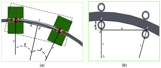
Figure 2.
Turning diagrams. (a) Whole-car double-chassis turning; (b) Single-chassis steering.
There are two steering devices either side of the front and rear load-bearing wheels of a single chassis. The steering devices comprise steering wheels, gap-adjusting interplates, and stiff springs. The steering devices are transformed by the expansion and contraction of the springs so that their guide wheels continuously fit on both sides of the track; i.e., the four guide wheels of a single chassis always fit on the track surface, as shown in Figure 2b. In the figure, point E is the tangent point between the rear guide wheel and the inner side of the track, and point F is the tangent point between the front guide wheel and the inner side of the track. The straight line l1 connects point E and the center of the guide wheel. A horizontal line is drawn from point F to cross the line l1 at point G. The distance k between points F and G is the horizontal distance (mm) between the tangent point of the front guide wheel and the inner side of the track to the center of the rear guide wheel on a two-dimensional plane. P is the distance between points E and G (mm), i.e., the compression amount of the steering spring in the steering device.
The horizontal distance between point F and the center of its guide wheel is negligible, and the distance k between points F and G is thus approximately equal to the distance between the centers of the two guide wheels on the same side for a straight track. According to Figure 2b, we have
The minimum turning radius of the chassis thus relates to the compression of the spring p and the distance k between the two guide wheels. With the maximum compression of the spring known, a smaller distance k between the two guide wheels corresponds to a smaller minimum turning radius. According to the actual transportation needs [17], while mm, mm, mm, for a body length of 1600 mm and body width of 800 mm, the minimum turning radius of the body is 800 mm because the distance between the two articulated discs is less than 1600 mm, and the theoretical minimum turning radius of the whole car is thus 3130 mm.
3.1.2. Analysis of the Climbing Capacity and Calculation of the Maximum Climbing Angle
The friction between the tire and track powers the overall car [18], and greater friction between the tire and track corresponds to a stronger driving force and better climbing ability [19]. As shown in Figure 3, the kinetic equation of the monorail car in the driving process is
where is the rotational inertia of the driving wheel (kg·m2); is the angular acceleration of the driving wheel (rad·s−2); is the driving torque of the wheel motor (Nm); is the friction acting between the wheel motor and track (N); and is the radius of the tire of the driving wheel (m). The relationship between the driving torque of the wheel motor and the power is obtained as follows:. If the wind resistance is ignored, when the monorail car is running on the horizontal track at constant speed in a straight line, . The driving wheel is the active wheel, subject to sliding friction, and the load-bearing wheel is the driven wheel, subject to rolling friction. The equilibrium formula of forces is , where is the normal reaction force of the track and the driving wheel (N), is the sliding-friction coefficient of the track and the driving wheel, is the normal reaction force (N) of the track and the driven wheel, and is the sliding-friction coefficient of the track and the driven wheel. Substituting this formula into Equation (2) yields
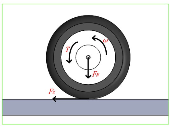
Figure 3.
Force analysis of the driving wheel.
As an actual application scenario, we consider an estimated weight of the overall car m > 660 kg, R1 = 0.15 m, and speed greater than 20 km·h−1. A material friction coefficient table gives = 0.05, assume = 0.30. For the monorail car traveling on a horizontal track at constant speed, the wheel motor power P should exceed 6.42 kW. Referencing a wheel motor model and parameter table, this paper takes the power of the wheel motor as 7 kW [20]. The theoretical value of is 0.33 after bringing P = 7 kW into Equation (3). If wind resistance is ignored, when the monorail car is running at constant speed on a climbing track, the kinematic formula is
Assuming that the climbing speed is 6 km·h−1 and other conditions remain unchanged, the theoretical maximum climbing angle is obtained as 28° for a total vehicle weight of 660 kg using Equation (4).
3.1.3. Design and Principles of the Anti-Tilt Device
The anti-tip device comprises a spring, base plate, vertical plate, and anti-tip wheel. The anti-tip wheel connects with the vertical plate through the base plate, and the vertical plate is fixed on the chassis of the car body with screws and nuts. The base plate and vertical plate are connected to the spring with coaxial bolts. When the car is running on a horizontal straight track, the base plate and vertical plate become vertical, whereas when the car is tilted, the angle between the base plate and vertical plate is adjusted accordingly through the spring, such that the overall car is balanced and there is no rollover. The running stability of the monorail car requires the maximum tilt angle of the monorail car on one side to be less than 5°. When the center of gravity of the car is on the right side of the track, the right anti-tip wheel interacts with the bottom of the track and stabilizes the whole car [21].
In Figure 4a, G is the gravitational force acting on the overall car (N), d1 is the horizontal distance of the center of gravity of the overall car from the midline of the track (mm), FN1 is the reaction force of the track acting on the tire (N), f1 is the friction force acting between the tire and track (N), d2 is the vertical distance from f1 to the bottom of the track (mm), FN2 is the reaction force of the track acting on the anti-sway wheel (N), f2 is the friction force acting between the anti-sway wheel and track (N), and d3 is the horizontal distance from f2 to the center line of the track (mm). If the center of gravity of the overall car is offset from the center to the right at a distance of d1, the center point at the bottom of the track is taken as the origin, and a force analysis of the overall car is carried out according to Figure 4a:
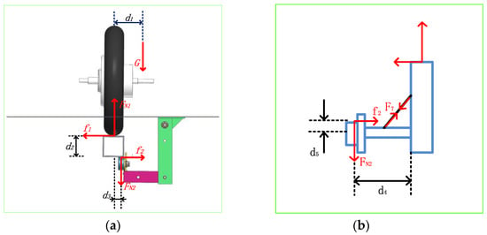
Figure 4.
Force analysis. (a) Whole-car force analysis (b) Force analysis of the anti-tip device.
The monorail car is assumed to have a maximum tilt of five to one side when it is moving down a horizontal, straight track. At this time, the monorail car is in a critical state of tilt, f1 reaches its maximum value, and =, brought into Formula (5) can be obtained:
The anti-tip device is then subjected to another force analysis, as shown in Figure 4b, where d4 is the distance from FN2 to the end of the horizontal plate (mm), d5 is the vertical distance from f2 to the center of the anti-tip wheel (mm), and FT is the tension of the spring (N):
The relationship between and can be obtained by combining Equations (5)–(7)
where is the coefficient of static friction acting between the tire and track, and is the angle between the spring and the bottom plate of the anti-tip device. We suppose that the carriage load is evenly distributed, the maximum load is 300 kg, the total weight of the car is 660 kg, and the maximum tilt angle of the monorail car on one side is 5°. is then 42.5° when the tilt angle of the monorail car is 5°, the static friction coefficient of the tire and the track [22]. According to the application scenario, the design body width is 800 mm, from the trapezoidal center of gravity calculation formula to get the maximum of d1 is 20 mm. The length of d2, d3, d4, d5 is 80, 30, 140, and 100 mm respectively. Then, at maximum load, the carriage undergoes a maximum deflection of 5°, and FT = 21,943 N. Currently, the spring elongation 4.2 mm, and the spring elasticity coefficient k ≥ 5224 N·mm−1 .
3.2. Simulation Experiments
The monorail car body size, wheel motor parameters, double-chassis dimensions, spring elasticity coefficient of the anti-tip device, and other key parameters are obtained through theoretical analysis and a three-dimensional model is established. To further verify the rationality of the design of the above key components, the three-dimensional model is imported into ADAMS software for simulation analysis [23,24]. After the steps of mechanism simplification, adding material information, restraint and spring and tire, a 660 kg load is applied and a 1:1 track model is established. The track is divided into a horizontal straight track, horizontal curved track, and climbing straight track. The length of the horizontal straight track is 20 m. The horizontal curved track is divided into 10 sections, each having a length of 10 m and a track radius of 3.5 to 2.6 m. The climbing straight track is divided into 10 sections, each having a length of 10 m and a track inclination of 18° to 27. The simulation experiment is shown in Figure 5.

Figure 5.
Monorail car simulation experiment. (a) horizontal straight track (b) climbing straight track (c) horizontal curved track.
According to the theoretical calculations and the actual working conditions, the simulation experiment is first conducted for the car traveling between 10 and 25 km·h−1 on the horizontal straight track and the sections of horizontal curved track with different radii of curvature, to verify that the car can travel normally under these conditions. The experimental results are given in Table 1.

Table 1.
Simulation experiment on straight and curved horizontal tracks.
The results of the simulation experiment show that the monorail car can travel normally when the track radius is greater than 3.2 m within the speed range of 10–25 km·h−1. The simulation experiment thus verifies that the maximum speed of the fully loaded car is 25 km·h−1 and the minimum turning radius is 3.2 m.
The simulation experiment is next conducted for the car traveling between 4 and 7 km·h−1 on the sections of climbing straight track with different gradients to verify whether the car can travel normally under these conditions. The experimental results are given in Table 2.

Table 2.
Simulation experiment on a climbing track.
The results of the simulation experiment show that the monorail car travels normally at a speed of 4–6 km·h−1 when climbing the straight rail track with a slope less than 24°. The simulation experiment thus verifies that the maximum slope that can be climbed by the fully loaded car is 24°. The maximum speed of the monorail car at this time is 6 km·h−1.
The simulation experiment is finally conducted for the car traveling between 0 and 25 km·h−1 with a center-of-mass vibration on the section of horizontal curved track having a turning radius of 3.2 m [25,26]. The maximum offset of the car’s center of gravity on both sides of the horizontal plane perpendicular to the track is recorded at different speeds. The experimental results are presented in Figure 6.
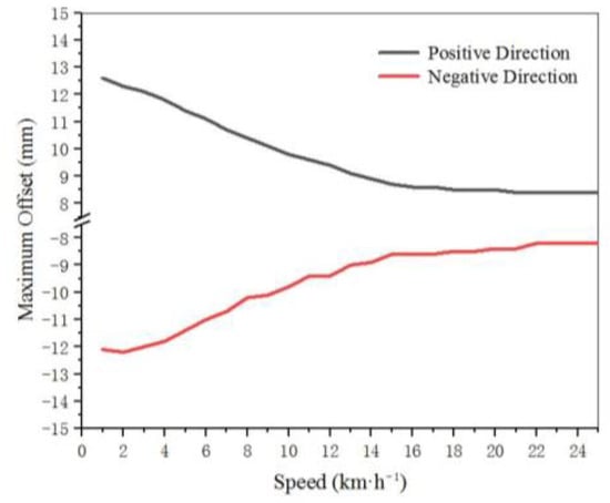
Figure 6.
Simulation experiment of a gravity offset.
The results of the simulation experiment show that when the car travels on the horizontal curved track with a turning radius of 3.2 m, the center of gravity of the car shifts more when the speed is low, and the maximum single-side offset is 12.6 mm. Assuming that the overall weight of the car is evenly distributed, and the height of the center of mass of the car from the track is 150 mm according to the dimensions of the monorail car, the maximum single-side tilt angle of the monorail car is obtained as 4.8°. The simulation experiment thus verifies that the monorail car anti-tip device can control the car within a single-side tilt angle of 5°.
The above simulation results show that the minimum turning radius and maximum climbing degree of the monorail car as well as the unilateral tilt degree are consistent with the theory, and the dual-chassis structure and the anti-sway device meet the design requirements.
3.3. Performance Testing
To verify the reliability of the theoretical design and simulation experiments of the monorail car, physical tests were conducted for the performance of the monorail car in terms of the maximum load capacity, maximum running speed at full load, climbing degree, minimum turning radius, and vibration of the car. The test track ran down two sides of a machinery manufacturing plant and had a total length of 100 m. The horizontal straight track was 20 m in length, the horizontal curved track was 30 m in length and had radii of curvature of 3.3, 3.2, and 3.1 m, and the climbing straight track was 50 m in length and had slopes of 25°, 24°, 23°, 22°, and 21°. The speed test instrument used was “WP20041X” wheel motor with its own data display program, the slope measurement instrument was “KeeGong-201811151450 digital-display inclinometer”, the vibration test instrument was “RS485 vibration sensor”, and the data collector was “LoRR collector”. The field test is shown in Figure 7a.
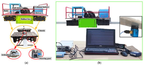
Figure 7.
Car site test. (a) Performance test charts (b) Vibration test chart.
3.3.1. Car Speed, Load, Turning, and Climbing Tests
To test the transport performance of the monorail car, the speed of the monorail car was adjusted linearly using an EM-100S Rand controller. The maximum speed of the car was tested at no load and at loads of 50, 100, 150, 200, 250, 300, and 350 kg on the horizontal straight, horizontal curved, and climbing straight sections of track. The results of tests and analyses of the transport performance parameters of the monorail car are given in Table 3.

Table 3.
Monorail car performance parameters.
The test results show that the maximum transport capacity of the monorail car was 300 kg, the maximum running speed with a full load was 20 km·h−1, the steepest slope was 21°, and the minimum turning radius was 3.3 m. The theoretical and simulation experiments ignored the friction and air resistance (other than the friction of the driving wheels) and the positive pressure of the driving wheels on the track due to the instability of the heavy load [27]. Therefore, the maximum running speed and the maximum climbing degree of the monorail car with a full load in the actual test were slightly less than the theoretical and simulation experimental values. Owing to random error in the installation of the actual test, the spring compression of the single-chassis steering device during turning of the car did not reach the theoretical value, and the minimum turning radius was thus slightly larger than the theoretical and simulation experimental values.
3.3.2. Vibration Test
To verify the anti-tip effect of the anti-tip device and the reliability of the theoretical and simulation results, the RS485 vibration sensor and LoRa data collector were used to collect data on the motion of the monorail car in three directions. The prototype equipment of the vibration test is shown in Figure 7b. The sensors were fixed at the level of the car’s center of gravity as the body and directly below the track [28,29,30].
With the car fully loaded under the working conditions, the vibration of the car and track was collected at a low traveling speed on the curved track with a radius of 3.3 m. The data of the single-side vibration frequency and amplitude were analyzed and processed to obtain the experimental results shown in Figure 8. In the figure, the x-direction is the horizontal direction perpendicular to the side of the track, the y-direction is the direction along the track, and the z-direction is the vertical direction perpendicular to the upper plane of the track.
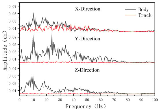
Figure 8.
Frequency amplitude comparison of the track and chassis.
The test results show that the amplitude of vibration of the car body was small, the vibration frequency was within 80 Hz in the three directions, and the car’s single-side amplitude of tilt was within 8 mm. The actual vibration amplitude was less than the theoretical and simulation values, and the anti-sway device thus had a certain anti-sway ability, in line with the design requirements [31].
4. Discussion
The monorail car uses a wheel hub motor as the power unit, with the friction between the wheel hub and the track as the driving force, with low kinetic energy loss and high transport efficiency, and its maximum driving speed can reach 20 km·h−1, while the existing gear-rack meshing monorail car generally operates at less than 7.2 km·h−1 [3,9], with its maximum operating speed increased by 177.8%. The paper innovatively uses the dual-chassis structure, so that the minimum turning radius of the monorail car is not affected by the body length. This ensures the transportation volume when the minimum turning radius of the monorail car is reduced to 3.3 m, and when the turning radius of the traditional monorail car is generally between 4 and 8 m [4,7]. The monorail car’s maximum turning radius is reduced by 17.5%. The anti-tip device designed in the paper improves the stability of the monorail car, reduces the vibration amplitude of its center of gravity to 8 mm, the maximum deflection of the whole car is less than 5° on one side, and the maximum load capacity reaches 300 kg. Compared with the 7YGS-45 transport car and other existing monorail car [3,4,7,9,18], the comprehensive transport performance of the friction-driven monorail car using the dual-chassis structure is excellent, especially the minimum turning radius and the maximum driving speed.
The dual-chassis structure designed in the paper effectively solves the problem of large turning radius of the monorail car, and the anti-tip device ensures the operational stability of the monorail. The use of wheel motors greatly improves its driving speed. The monorail car is economical and environmental friendly, with high transportation efficiency, which solves the problem of labor shortage in today’s increasingly serious problem of aging population. It also provides a new solution to the problem of forest fruit transportation in hilly mountains, and lays the foundation for intelligent transportation of forest fruit in mountains.
The friction-driven monorail car powered by a wheel hub motor has good transport performance, high transport efficiency and great development potential, which is the development direction of forest fruit transportation equipment [20]. Compared with gear-rack meshing monorail car, this car is only suitable for low slope mountainous hilly forest area or special plain forest fruit park due to the limitation of the friction coefficient between wheel and track. In further research, improvements will be made for its mechanical structure or friction coefficient to improve the climbing ability of monorail car, expand the scope of application, and further improve the mechanization level of forest fruit transportation in hilly mountainous areas.
5. Conclusions
An electric monorail car with friction drive is developed in this paper, with a double chassis structure and an anti-sway device. Key parameters were derived from theoretical analysis, and their feasibility was verified by the Adams simulation test. The transport performance of monorails and the related conclusions were derived from practical tests.The main findings of the paper are as follows.
- (a)
- A theoretical basis for designing monorail vehicles of mountain forests and other similar transportation machines is provided in this paper.
- (b)
- The proposed monorail car ran well and passed a transportation test in that it met the requirements of the transportation of forest fruit on the low slopes of mountains. The maximum weight of the car was 300 kg. The maximum speed at full load was 20 km·h−1. The minimum turning radius was 3.3 m. The maximum climbing degree was 21°. The transportation efficiency was high, the stability was good, and the car thus met the requirements of transportation design.
- (c)
- The innovative double-chassis structure and steering device designed in this paper were verified to be feasible in a theoretical calculation, simulation experiment, and physical test, and the minimum turning radius of the monorail car was reduced to 3.3 m, which met design requirements.
- (d)
- The anti-tilt device designed in this paper effectively prevented the monorail car from tilting. The deflection of the center of gravity of the overall car was controlled within 12.6 mm, and the tilt of the body was controlled within 5° on one side, allowing the car to run more stably on the track.
Author Contributions
Conceptualization, H.X. and D.X.; methodology, H.X. and C.Z.; software, H.X.; validation, H.X. and C.Z.; formal analysis, H.X. and D.X.; investigation, H.X. and C.Z.; resources, W.L.; data curation, X.B.; writing—original draft preparation, H.X.; supervision, D.X. and X.B. All authors have read and agreed to the published version of the manuscript.
Funding
This research was funded by the National Key Research and Development Program of China (2019YFD1002401).
Institutional Review Board Statement
Not applicable.
Informed Consent Statement
Not applicable.
Data Availability Statement
Test methods and data are available from the authors upon request.
Acknowledgments
This work was supported by the National Key Research and Development Program of China (2019YFD1002401). We thank Liwen Bianji (Edanz) for editing the language of a draft of this manuscript.
Conflicts of Interest
The authors declare no conflict of interest.
References
- Arthur, C.N.; Robert, H. Influence of Rail Transit on Development Patterns in the Mountain Mega-Region with a Surprise and Implications for Rail Transit and Land-Use Plannin. Transp. Res. Rec. 2021, 2675, 374–390. [Google Scholar]
- Ján, K.; Pavel, Ť.; Pavol, H.; Jozef, K.; Zdeněk, A. The Operational Reliability Analysis of Machinery: A Case Study of Forest Forwarders and Their Technological Equipment. Forests 2021, 12, 404. [Google Scholar]
- Yue, L.; Zhen, L.; Tian, H.; Shi, L.; Shu, S.; Shuang, H. Design of drive system for battery-drive monorail transporter for mountainous orchard. J. Agric. Eng. 2017, 33, 34–40. [Google Scholar]
- Chen, Y.; Hong, T.; Sun, T. Analysis on minimum turning radius and maximum carrying capacity of monorail vehicles for mountain orchard. J. Agric. Eng. 2012, 28, 50–56. [Google Scholar]
- Yamamoto, S.; Kanamitsu, M.; Ajiki, K.; Fujiwara, M.; Tanaka, K. S-shaped multipurpose monorail for hillside orchards. Jpn. Agric. Res. Q. JARQ 2018, 41, 147–152. [Google Scholar] [CrossRef]
- Li, J.; Zhong, M.; Zhang, Y.; Bao, X.; Li, S.; Liu, M. Optimized design of the power consumption test of mountain orchard transporters. Int. J. Agric. Biol. Eng. 2021, 014, 107–114. [Google Scholar] [CrossRef]
- Li, S.; Xing, J.; Zhang, Y.; Meng, L.; Fan, Q. 7YGS-45 type self-propelled double-track mountain orchard transporter. J. Agric. Mach. 2011, 42, 85–88. [Google Scholar]
- Yu, O.; Tian, W.; Tian, H.; Xu, S. Calibration and Analysis of Mechanical Modeling for Traction Wire Rope of Mountainous Orchard Carrier. Sci. Math. Probl. Eng. 2021, 2021, 7391524. [Google Scholar] [CrossRef]
- Zhang, K.; Zhang, Y.; Zhou, B.; Yuan, Q.; Lu, G.; Zhao, L. Driving Performance of Single-track Rubber Roller Driving Device. J. Agric. Mach. 2013, 44, 111–116. [Google Scholar]
- Xiao, W.; Linkui, H.; Zixue, D.; Liang, C.; Zhen, Y. Research on parameter optimization based on multi-body dynamics model of monorail vehicle aiming at reducing running wheel wear. Proc. Inst. Mech. Eng. Part K J. Multi-Body Dyn. 2022, 236, 588–601. [Google Scholar]
- Leng, H.; Ren, L.; Ji, Y.; Huang, Y. Radial adjustment mechanism of a newly designed coupled-bogie for the straddle-type monorail vehicle. Veh. Syst. Dyn. 2019, 58, 1407–1427. [Google Scholar] [CrossRef]
- Gaevskiy, V.V.; Ivanov, A.M. Problems of the application of intelligent driver assistance systems on a single-track vehicles. J. IOP Conf. Ser. Mater. Sci. Eng. 2018, 386, 012021. [Google Scholar] [CrossRef]
- Ali, S.; Yıldız, S.; Sivrioğlu. Improving curving performance of a straddle type monorail vehicle by using semi-active devices. Int. J. Heavy Veh. Syst. 2021, 28, 385–408. [Google Scholar]
- Ji, Y.; Ren, L.; Huang, Y. Passive radial mechanism of a bogie with the auxiliary steering device for the straddle monorail vehicle. Veh. Syst. Dyn. 2020, 59, 1–25. [Google Scholar]
- Yongzhi, J.; Pingbo, W.; Jing, Z.; Hao, G. Comparison of the curve negotiation properties of two different articulated monorail vehicles. Proc. Inst. Mech. Eng. Part F J. Rail Rapid Transit 2019, 233, 831–843. [Google Scholar]
- Zou, J.; Chen, B.; Zhan, S.; Huang, C.; Wang, X. Theoretical Derivation of Gauges for Straddle-type Monorail Vehicle. Sci. J. Phys. Conf. Ser. 2021, 1910, 012052. [Google Scholar] [CrossRef]
- Subarmono; Wibisono, M.A.; Pujawira, T.I. Light Monorail Body Carriage Design. Appl. Mech. Mater. 2016, 4225, 259–265. [Google Scholar] [CrossRef]
- Maciel, G.P.R.; Barbosa, R.S. Monorail vehicle model to study influence of tyre modelling on overall dynamics. Int. J. Heavy Veh. Syst. 2016, 23, 317–332. [Google Scholar] [CrossRef]
- Lu, C.; Bo, D.; Yu, C. Analysis of Running Stability and Tire Wear of Monorail Vehicles. Sci. IOP Conf. Ser. Earth Environ. Sci. 2019, 267, 042078. [Google Scholar] [CrossRef]
- Corno, M.; Panzani, G.; Savaresi, M.S. Single-Track Vehicle Dynamics Control: State of the Art and Perspective. IEEE/ASME Trans. Mechatron. 2015, 20, 1521–1532. [Google Scholar] [CrossRef]
- Zhang, R.; Ji, Y.; Ren, L. Pre-load on the guiding/stabilizing wheels and the critical lateral force of a straddle-type monorail vehicle. Proc. Inst. Mech. Eng. Part F J. Rail Rapid Transit 2019, 233, 160–169. [Google Scholar] [CrossRef]
- Yuan, J.; Li, R. Anti-overturning capacity and critical roll angle of straddling monorail vehicle. Proc. Inst. Mech. Eng. Part C J. Mech. Eng. Sci. 2018, 232, 4420–4429. [Google Scholar]
- Zhou, X.; Zi, D.; Zhen, Y.; Liang, C. Research on Vertical Coupling Dynamics of Monorail Vehicle at Finger-Band. Urban Rail Transit 2017, 3, 142–148. [Google Scholar]
- Jun, Z.; Zi, D.; Zhen, Y.; Zhou, X. Dynamic parameters optimization of straddle-type monorail vehicles based multiobjective collaborative optimization algorithm. Veh. Syst. Dyn. 2020, 58, 357–376. [Google Scholar]
- Yong, J.; Ping, W.; Jing, Z.; Xing, W.; Yun, Z.; Zhen, Y.; Run, G.; Xin, D. Researches on the resonance of a new type of suspended monorail vehicle-bridge coupling system based on modal analysis and rigid-flexible coupling dynamics. Veh. Syst. Dyn. 2021, 59, 135–154. [Google Scholar]
- Kai, L.; Kaiyun, W.; Zhihui, C.; Cheng, C.; Li, G. Influence of Wheel Eccentricity on Vertical Vibration of Suspended Monorail Vehicle: Experiment and Simulation. Shock. Vib. 2017, 2017, 1–10. [Google Scholar]
- Zou, Y.; Liu, Z.; Shi, K.; Song, J.; He, X.; Liu, Q. Experimental Study of the Aerodynamic Characteristics of a Suspended Monorail Vehicle-Bridge System Under Crosswinds. Sci. Int. J. Struct. Stab. Dyn. 2022, 22, 2241007. [Google Scholar] [CrossRef]
- Qing, H.; Yun, Y.; Cheng, C.; Sheng, Z.; Wan, Z. Experimental Investigation on Coupled Vibration Features of Suspended Monorail Train–Bridge System under Constant Speed and Braking Conditions. Sci. Int. J. Struct. Stab. Dyn. 2021, 21, 2150177. [Google Scholar] [CrossRef]
- Zi, D.; Liang, X.; Zhen, Y. Improving ride comfort of straddle-type monorail vehicle with single-axle bogie by active suspension. Noise Vib. Worldw. 2021, 52, 334–344. [Google Scholar]
- Yildiz, A.S.; Sivrioglu, S. Semi-active Vibration Control of Lateral and Rolling Motions for a Straddle Type Monorail Vehicle. IFAC Pap. 2016, 49, 279–284. [Google Scholar] [CrossRef]
- Du, Z.; Junchao, Z.; Zhen, Y. The research on operational reliability evaluation of straddle-type monorail vehicle. Syst. Sci. Control Eng. 2018, 6, 537–546. [Google Scholar] [CrossRef]
Disclaimer/Publisher’s Note: The statements, opinions and data contained in all publications are solely those of the individual author(s) and contributor(s) and not of MDPI and/or the editor(s). MDPI and/or the editor(s) disclaim responsibility for any injury to people or property resulting from any ideas, methods, instructions or products referred to in the content. |
© 2023 by the authors. Licensee MDPI, Basel, Switzerland. This article is an open access article distributed under the terms and conditions of the Creative Commons Attribution (CC BY) license (https://creativecommons.org/licenses/by/4.0/).