Article

Effect of Pre-Heating and Post-Heating on Electron Beam Welding of Reduced Activation Ferrite/Martensite Steel

1
Institute of Plasma Physics, Hefei Institutes of Physical Science, Chinese Academy of Sciences, Hefei 230031, China
2
Science Island Branch, University of Science and Technology of China, Hefei 230026, China
3
Anhui Province Key Laboratory of Special Welding Technology, Huainan 232000, China
4
CAS Key Laboratory of Soft Matter Chemistry, Department of Polymer Science and Engineering, University of Science and Technology of China, Hefei 230026, China
*
Author to whom correspondence should be addressed.
J. Nucl. Eng. 2021, 2(3), 225-238; https://doi.org/10.3390/jne2030021
Submission received: 31 March 2021 / Revised: 8 June 2021 / Accepted: 17 June 2021 / Published: 23 June 2021

Abstract

:
Reduced activation ferritic/martensitic (RAFM) steels are considered the main candidate material for the water-cooled ceramic breeder (WCCB) in a fusion reactor. High-energy density welding approaches, such as electron beam welding (EBW) and laser beam welding (LBW), are frequently utilized in the welding of RAFM steels. During the welding process, cracks and other defects are prone to appear. In this paper, EBW was selected for the welding of RAFM steels. Those with and without pre-heat and post-heat treatment by electron beams are studied by finite element simulation and trials. The results show that the experimental results are consistent with the simulation. In particular, in the case of similar deformation, the residual stress after electron beam heat treatment is far less than that without heat treatment. Without heat treatment, the residual stress near the weld is more than 400 MPa, while the residual stress after heat treatment is about 350 MPa. As the reduction of residual stress is essential to prevent the occurrence of cracks and other defects after welding, pre-heat and post-heat treatment by the electron beam is deemed as an effective way to greatly improve the welding quality in RAFM steel welding.

1. Introduction

In terms of scale, the energy potential of fusion is superior to all other energy sources we know on Earth [1,2,3]. Fusing atoms together in a controlled way releases millions of times more energy than a chemical reaction, such as burning coal, oil or gas, and several times more energy than nuclear fission. Reduced activated ferrite/martensite (RAFM) steels are considered the main candidate material for the structural applications of fusion reactor components, such as the water-cooled ceramic breeder (WCCB) [4,5]. Many countries in the world have done a lot of work in developing and characterizing these materials, such as CLAM in China [6], F82H in Japan [7,8], EUROFER97 in the European Union (EU) [9] and Rusfer EK-181 [10]. Meanwhile, due to the complex structure of the WCCB blanket and extremely harsh service conditions, the quality of the welding plays a decisive role in the feasibility and safety of the fusion reactor operation [11]. The welding methods suitable for RAFM steels include tungsten inert gas (TIG) welding, electron beam welding (EBW), and laser beam welding (LBW), etc. [12]. Due to the advantages of no pollution of the welding joints, high efficiency, large depth width ratio of the weld, and small heat affected area, EBW was determined to be the main WCCB blanket manufacturing technique [13]. In the welding process, the residual stress, hardness and brittleness of EBW joints of RAFM steels are very high due to the influence of thermal expansion and cold contraction, δ ferrite, carbide and chromium produced at high temperature. Therefore, cracks and other defects can easily occur during rapid cooling after welding [14,15]. R. Lindau [16], Hu Jie [17], Jiang Zhizhong [6], et al., studied the hardness and brittleness of the EBW-joints of RAFM steels by post heat treatment. However, there is little research on reducing residual stress and preventing weld cracks by changing the EBW process. The research shows that finite element simulation can be used as a powerful tool to analyze the welding performance based on scientific principles. It can provide quantitative information for the characteristics of thermal cycle, residual stress, strain, and deformation in the welding process. In the past, a lot of finite element simulation studies have been carried out on LBW, EBW and other welding methods [11,18,19,20,21,22,23,24,25].
In this paper, through the finite element software MSC Marc (2019) of MSC company in Los Angeles, CA, USA. the temperature field, residual stress, and deformation of 0.023 m thick-RAFM steels during different EBW processes were analyzed by means of experiment and finite element simulation. The temperature field distribution, stress distribution, and deformation of welded parts after welding are discussed, which provides a reference for the welding process of WCCB blanket.

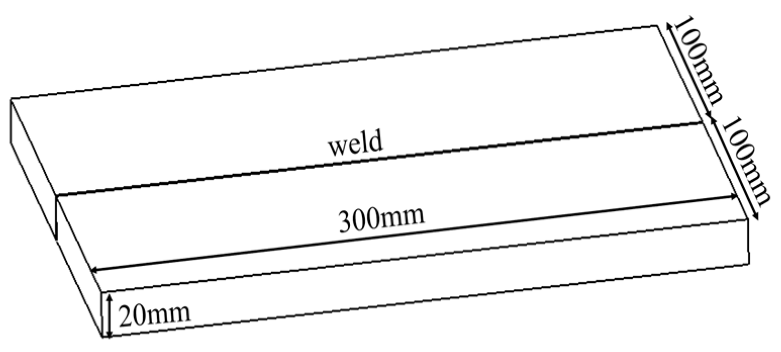
2. Experimental Conditions

The test material is RAFM steels, the chemical composition of which was measured by direct-reading of the spectrometer as shown in Table 1; the direct-reading of the spectrometer is shown in Figure 1; and the material properties are shown in Table 2 [12,26]. The sizes of the six test plates were 0.3 m × 0.1 m × 0.023 m (two of them were the heat source verification board). Surface scale on the steel plates were removed by mechanical polishing and then they were cleaned with anhydrous ethanol. The equipment for welding was a ZD150-60C CV66M chamber electron beam machine with the highest welding voltage of 150 kV at the Key Laboratory of Special Welding Technology (Huainan, China) (Figure 2). The vacuum pressure was about 1.7 × 10⁻⁸ MPa, and the volume of the vacuum chamber was 66 m3. The welding method of test plates is shown in Figure 3. Meanwhile, in order to obtain high-quality welds, electron beam scanning deflection was used in the welding process. The schematic diagram of electron beam scanning deflection is shown in Figure 4 [27]. The scanning deflection was to control the electron beam with a predetermined curve through a function generator, which makes the electron beam move in a straight line and a certain waveform (circle, triangle or square (Figure 4c)). This strong vibration stirring can improve the metal melting and solidification process, prohibit molten envelopes, refine the grain, and reduce the root spiking of the welds [27,28].
At the same time, in order to obtain an excellent welding joint, welding parameters such as beam current, focusing current, and welding speed were optimized before the test. The parameters after being optimized are shown in Table 3. Four of the six test plates were welded by butt welding in pairs (two of which were used as heat source verification). For the remaining two test plates, we first clamped and fixed them on the base plate, pre-heated them by electron beam, and then welded them after 30 s. After the welding was completed, the first post-heating followed, and the second post-heating was carried out after 40 s. The heat treatment temperature was lower than the melting point temperature of RAFM steels. There was no need to add filler during welding.
X-ray testing equipment, XXG-2505, was used to examine the quality of the welding joint. The applied voltage was 280 kV, the focal length was 0.6 m, and the current was 0.005 A. The quality of the image was verified by a wire image quality indicator (IQI). The minimum IQI value was W12 according to the standards ISO17636, and no defects were found.
The blind hole [29] method was used to detect welding residual stress by the residual stress detector of HK21B. When measuring the residual stress, connected the test plate, the strain gauge, and strain instrument with compensation correction function, opened the strain instrument and started drilling. After the reading is stable, read the strain in all directions. The hole depth should be the same during the measurement. Because there is only one middle weld, the residual stress near the weld is large and changes violently, and its value decreases as move away from the weld. Due to symmetrical distribution on both sides of the weld, we only select the points on one side of the weld to study, the test points are relatively dense in the area close to the weld area, and the test points far away from the weld are relatively loose (Figure 5) (the residual stress at the weld cannot be measured because of the reinforcement, thus we only measure the residual stress on the heat-affected zone and base metal).
Under different welding processes, the results of deformation and residual stress were compared and analyzed by experiment and finite element simulation, and the most suitable welding process was selected.

3. Finite Element Modeling

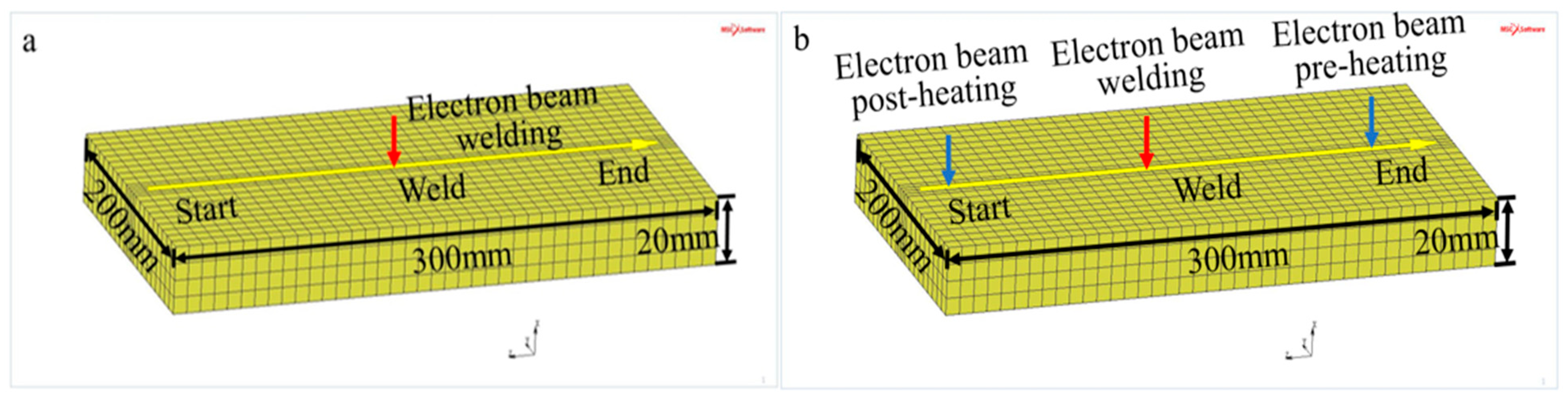
3.1. Finite Element Model

A three-dimensional finite element model was established by using the simulation software, and the thermal elastoplastic analysis method was used in this study. The whole model was composed of 3520 eight-node hexahedral elements with the capabilities of large deformation and strain. In the selection of element size, the calculation efficiency and result accuracy should be considered at the same time. Finally, the maximum element size should be 5 × 10⁻³ m, and the meshes near the weld should be refined (Figure 6), Figure 6a shows the finite element model of one time welding, and Figure 6b is the finite element model of pre-heating, welding and post heating. In the finite element analysis, we assumed that the material obeys von Mises yield criterion. On this basis, because EBW is carried out in a vacuum, other heat transfer is neglected except irradiation. The efficiency was assumed to be 90%.

3.2. Heat Conduction Equation

In the process of EBW, due to the high energy density and fast welding speed of the electron beam, when the electron beam acts on the surface of the workpiece, the melting and solidification process of the metal occurs in an instant. With the movement of the heat source, the temperature of the whole weldment changes rapidly with time and space, and the thermophysical properties of the material also change rapidly with the change of temperature. Therefore, the analysis of the welding temperature field is a typical non-linear transient heat conduction problem. In the Cartesian coordinate system, supposing that the heat source of the electron beam moves in the positive X-direction, its control equation can be written as follows [30]:
ρ C p T t   = X ( k x y x ) + y ( k y T y ) + z ( k z T z ) + Q ˙
where ρ, Cp, and k are the density, specific heat, and heat conductivity of the material respectively, T is the temperature. It is assumed that the material is isotropic in X, Y and Z-directions, then k x = k y = k z , so Equation (1) can be simplified as:
ρ C p T t   = k ( 2 T 2 X + 2 T 2 y + 2 T 2 z ) + Q ˙

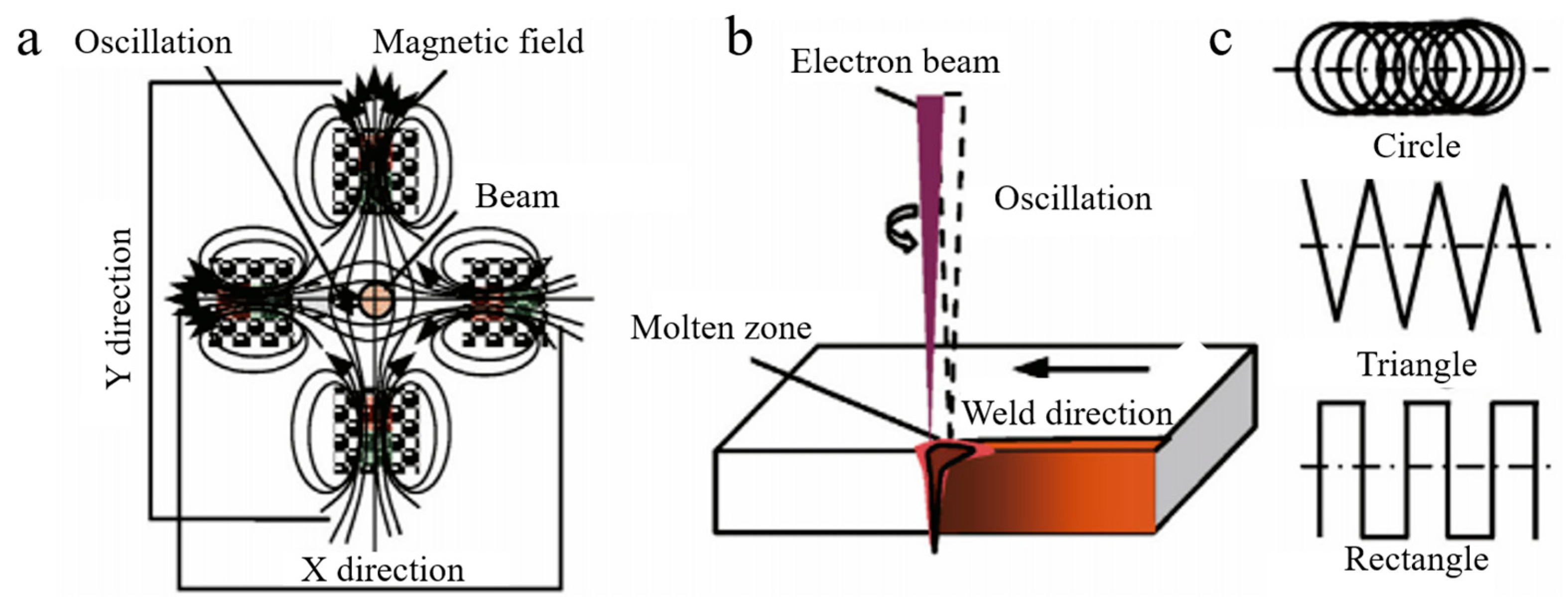
3.3. Heat Source Model

For the Gauss model, the penetration of the arc is not considered. Therefore, Goldak’s double ellipsoid heat source distribution model is adopted in our study. Assuming that the energy fractions of the front and back ellipsoids are f s and f p respectively, and f s + f p = 2, then the heat source distribution of the front and back ellipsoids are as follows [31]:
q ( x , y , z ) = 6 3 f s Q π a b c 1 π e 3 x 2 / a 2 e 3 y 2 / b 2 e 3 z 2 / c 1 2
q ( x , y , z ) = 6 3 f p Q π a b c 2 π e 3 x 2 / a 2 e 3 y 2 / b 2 e 3 z 2 / c 2 2
where Q is the input heat source power, a, b, c1, c2 are the parameters defining the shape of the ellipsoid, c1, c2 are the length of the front and back ellipsoids respectively, a is the width of the weld, and b is the depth of the weld. The energy density of the EBW pool is given by the following Equation (5) [32]:
q ( x , y , z , t ) = 6 3 Q π a b c π exp ( 3 x 2 / a 2 ) · exp ( 3 y 2 / b 2 ) · exp { [ z + v ( τ t ) ] 2 / c 2 }
where Q is the power of EBW, v and t are the EBW speed and welding time respectively, and c is the energy distribution parameter.

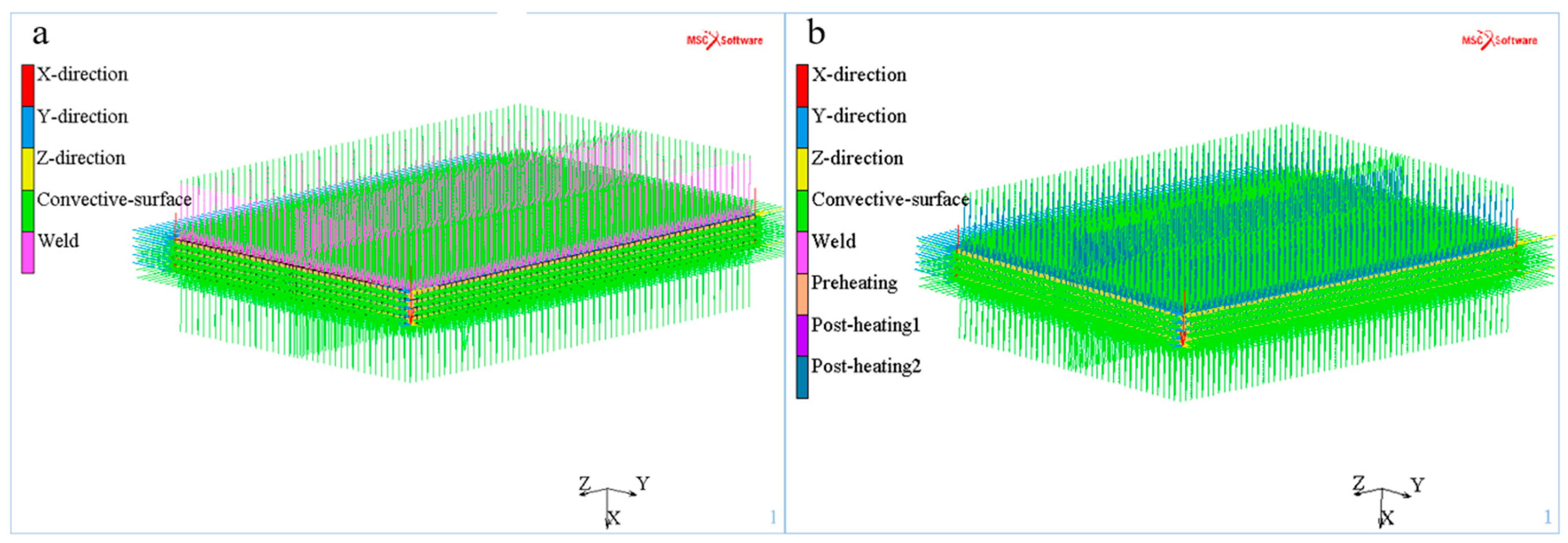
3.4. Boundary Conditions

EBW was carried out in a vacuum chamber, and radiation heat dissipation was set as the main heat dissipation mode in MSC Marc software [31]:
H = 24.1 × 10 4 ε T 1.61
where ε is the emissivity or degree of blackness of the surface.
In the finite element model, we define the X, Y, and Z-direction constraints according to the actual welding situation, and all the outer surfaces of the test plate are defined as heat dissipation surfaces, as represents in Figure 7, where the X, Y, and Z directions in the figure refer to the constraints of the X, Y, and Z directions.

4. Results and Discussion

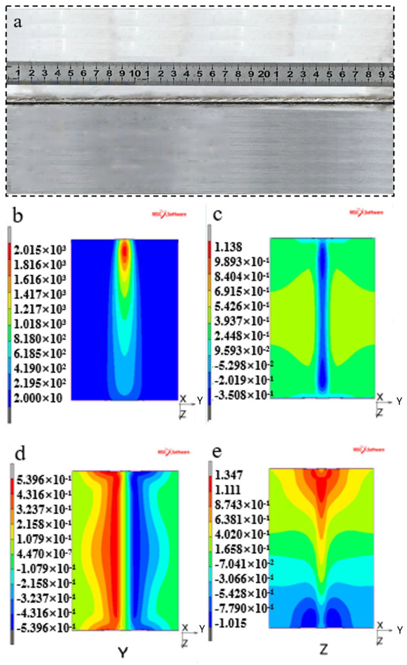
4.1. Verification of Heat Source Model

Firstly, the heat source is checked by simulation combined with the test. After welding, the transverse contraction of the test plate is 0.9 × 10⁻³ m, and the maximum width of the weld is 6.5 × 10⁻³ m (Figure 8a). The dotted line in Figure 8a indicates the width of the original test plate, and the points A, B, C and D represent the specific positions for measuring the deformation of the test plate in the X-direction, through the measurement of the machine tool, the deformations of the four positions in the X-direction are 0.29 mm, 0.27 mm, 0.32 mm and 0.35 mm, respectively. Figure 8b–e shows the finite element simulation results of the test plate. In the welding process, the maximum temperature is 2288 K (Figure 8b), and the transverse shrinkage is 1.079 × 10⁻³ m (Figure 8d). The maximum deformations in the X direction and the Z direction are 1.14 × 10⁻³ m (Figure 8c) and 1.35 × 10⁻³ m (Figure 8e), respectively. The results show that the deformation of finite element simulation is in good agreement with that of the welding test. Therefore, in the subsequent welding simulation, the checking heat source and boundary condition can be used continuously.

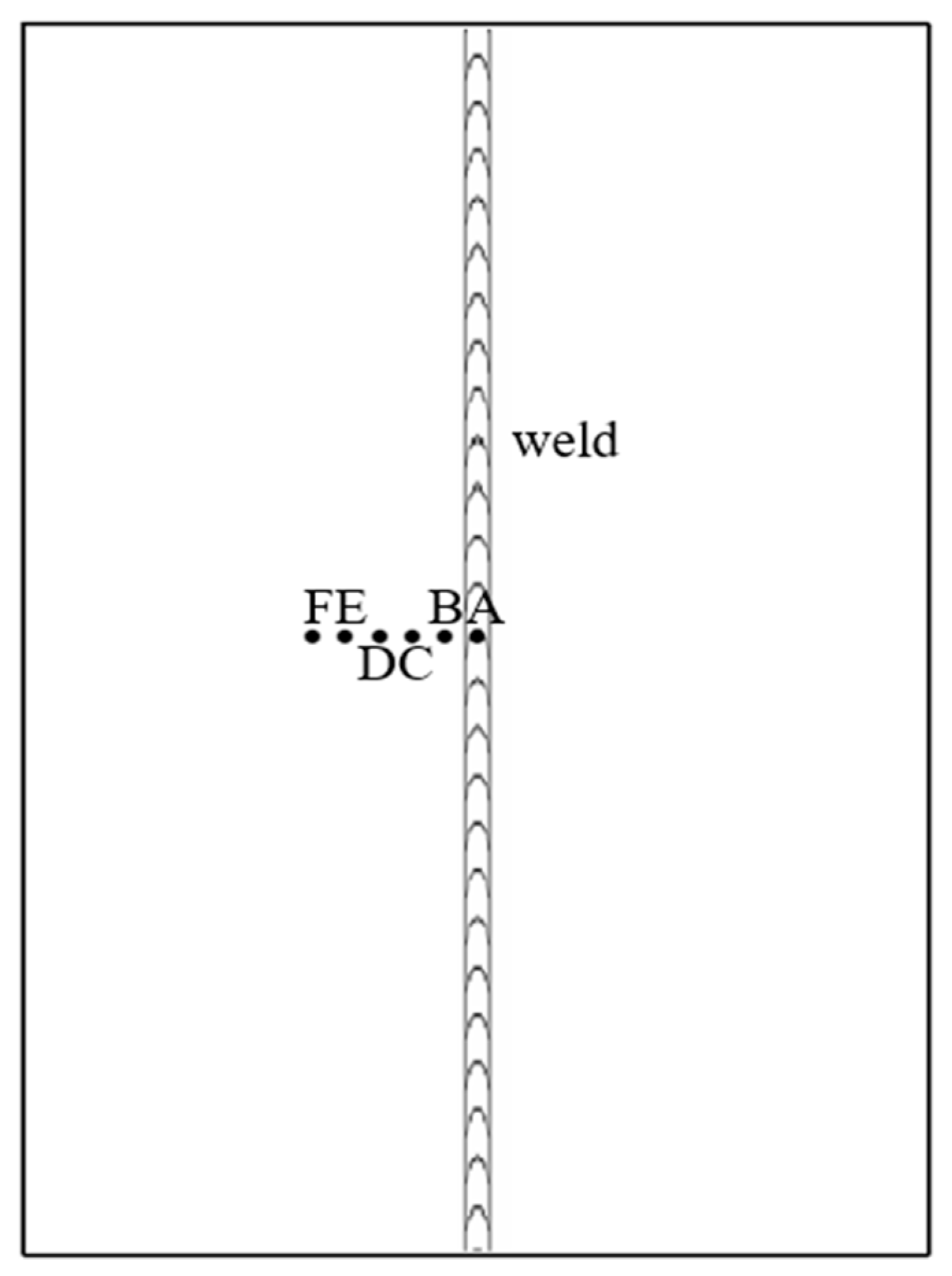
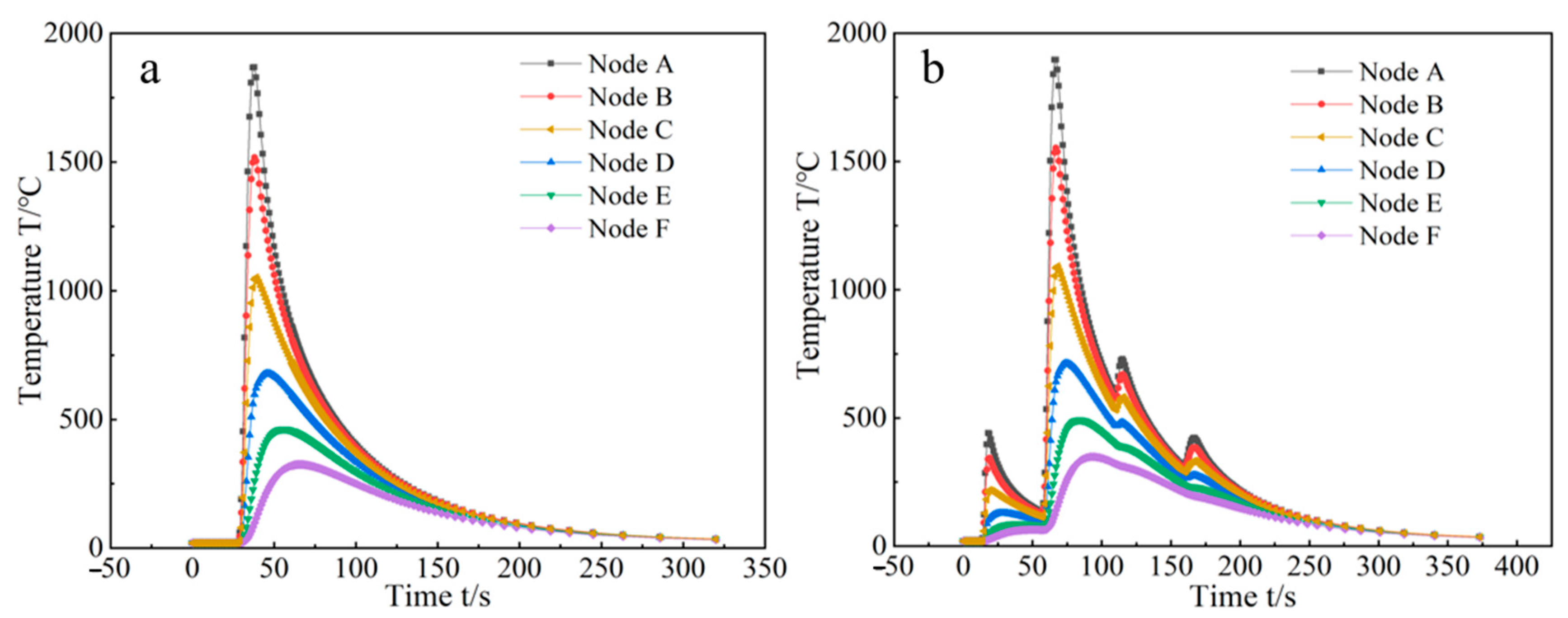
4.2. Welding Temperature Field

Figure 9 is the front view of the test plate after EBW. Six points on the surface of the test plate were taken to analyze the temperature field distribution. As shown in the figure, the distance between the six points is 3 × 10⁻³ m, and point A is in the middle of the weld.
Figure 10 shows the temperature change of six points with time during welding. It can be seen from Figure 10a that the temperature of the weld centerline exceeds 2173 K, and the temperature of point B is higher than the melting point temperature of the material, so it is also in the melting zone. During welding, the highest temperature of the C~F point is below the melting point of RAFM steels, so these four points are in the heat-affected zone of the weld. As shown in Figure 10b, the pre-heating temperature before welding was between 473 K and 773 K. The welding temperature is the same as that of the one time welding. After welding, the electron beam was used two times for rapid heating to delay the rapid cooling process. The first heating temperature was higher than the second heating temperature.
As shown in Figure 10b, the pre-heating temperature before welding was between 473 K and 773 K (the test pre-heating temperature was 723 K). The welding temperature is the same as for one welding. After welding, the electron beam was used two times for rapid after-heating according to the test heating temperature (723 K and 623 K) to delay the rapid cooling process. Compared with Figure 10a,b, it is found that the cooling time of pre-heating after welding is nearly 30 s longer than that of one welding. Reducing the cooling rate after welding has a great effect on preventing cracks in RAFM steels during rapid cooling after EBW with high energy density.

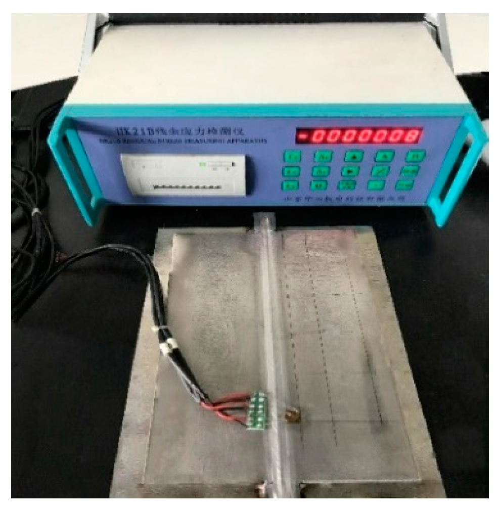
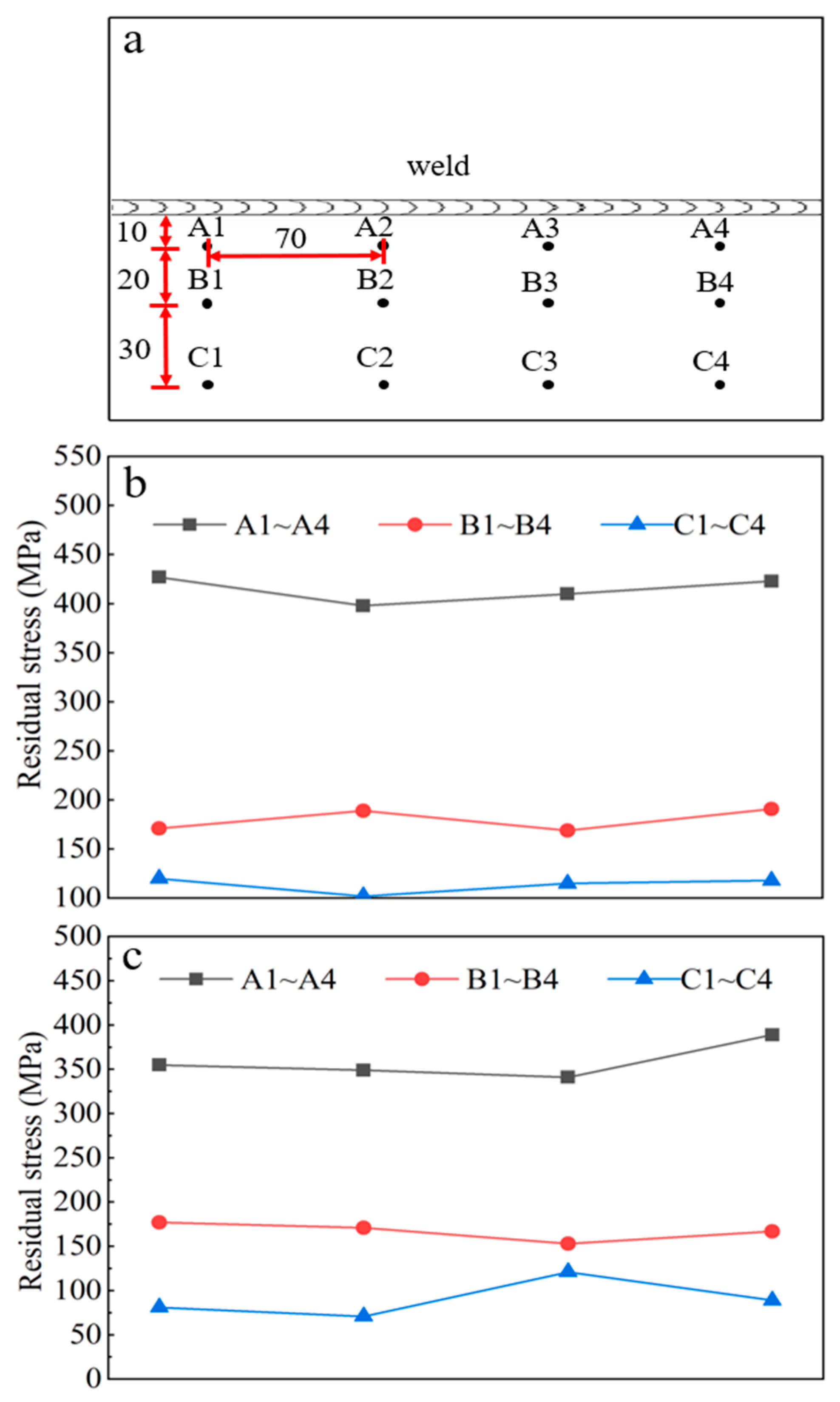
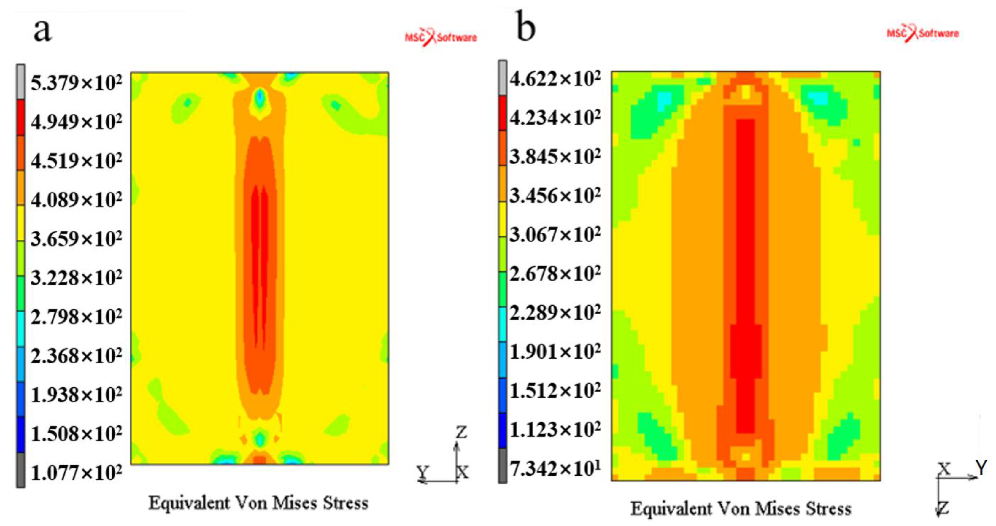
4.3. Residual Stress

The distribution of residual stress in the heat-affected zone and base metal under different welding processes was measured by the blind hole method. Because the residual stress on both sides of the weld has the characteristic of symmetrical distribution, we only tested one side (there is reinforcement at the weld, which cannot be measured, and removing the reinforcement will affect the stress distribution) (Figure 11). Figure 11a represents the distribution of the strain gauge when measuring the residual stress on the test plates. The transverse distances of points A1~A4, B1~B4, and C1~C4 from the weld were 1 × 10⁻² m, 3 × 10⁻² m, and 6 × 10⁻² m respectively, and the distance between each point in the longitudinal direction of the weld was 7 × 10⁻² m. Figure 11b,c show the stress distribution under different welding processes. Under one-time welding process, the maximum residual stress and the minimum residual stress are about 400 MPa and more than 100 MPa, respectively (Figure 11b). Under the pre-heating, welding and post heating process, the residual stress decreases as a whole, more in the heat affected zone and slightly in the base metal, and the maximum value is about 350 MPa, and the minimum value is about 80 MPa (Figure 11c). It can be seen that the welding residual stress is greatly reduced under pre-heating and post heating. This is mainly because pre-heating and post heating reduce the thermal impact of the electron beam on the test plates and the welding temperature gradient. It plays an important role in preventing the weld cracks.
The equivalent stress under different welding processes is obtained by finite element simulation analysis (Figure 12). Figure 12a,b are the simulation results of cooling to below 323 K after welding. The common feature is that the equivalent stress is concentrated near the welds and increases with distance; it gradually decreases and becomes uniform. The equivalent stress is mainly caused by the thermal expansion and cold contraction in the process of metal melting and solidification, the huge temperature gradient inside and around the weld, and the large thermal impact. The maximum equivalent stress of the one-time welding process is 537.9 MPa. The maximum equivalent stress of pre-heating, welding, and post-heating is 462.2 MPa, which is less than that of the one-time welding process. The main reason is that pre-heating, welding, and post-heating reduce the cooling rate, thermal shock, and temperature gradient of EBW. Compared with Figure 11 and Figure 12, the results show that the equivalent stress of the weld under pre-heating, welding, and post-heating is less than that of the weld after one-time welding. These results are similar when the transverse distance is 1 × 10⁻² m from the welds. The simulation results are larger than the test results at the position 2 × 10⁻² m and further away from the welds. There are two main reasons for this. Firstly, the test plate must be removed from the clamping position when measuring the residual stress, which will lead to partial release of residual stress. Secondly, the test results were measured after the test plate was welded and, in this process, the residual stress on the base metal was partially released.

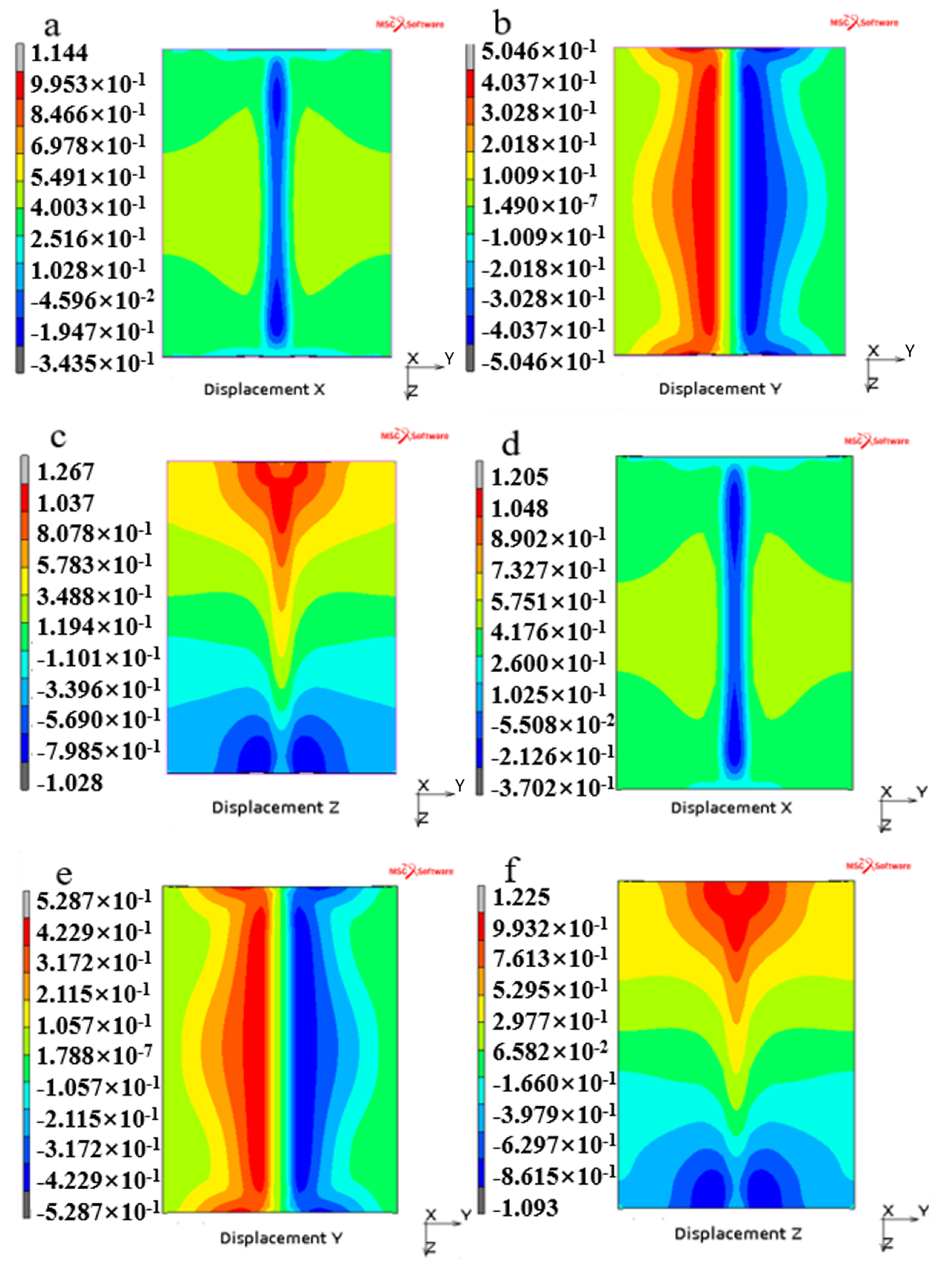
4.4. Welding Deformation

Under the one-time welding process, the deformation of test plate in X, Y, and Z directions is shown in Figure 13a–c. The deformation of the test plate in X, Y, and Z directions during pre-heating, welding and post-heating is shown in Figure 13d–f. By comparing a and d in Figure 12, the maximum deformation of the test plate under pre-heating, welding, and post-heating process is greater than that of the test plate under the one-time welding process in the X-direction, and the maximum deformation of a diagram and d diagram occurs at the welding seam, it shows that the maximum deformation of the test plates in the X direction caused by weld reinforcement. As represented in Figure 13b,e, it can be found that the deformation of the test plate in the Y direction is slightly smaller under the one-time welding process. However, the position of the maximum deformation is similar under the two welding processes, which occurs at both ends and in the middle of the test plates. Figure 13c,f, show the deformation of the test plates in the Z direction. In the Z direction, the deformation of the two welding processes is similar, and the maximum deformation position is also similar, which mainly occurs at both ends of the weld. The finite element simulation results of the test plate are basically consistent with the test results.
By comparing the deformation of the test plate in three directions under the two welding processes, we can find that, in the welding process, pre-heating and post-heating of the weld have little effect on the deformation of the weld. Therefore, only the residual stress is considered, and it is beneficial to reduce the residual stress by pre-heating and post-heat treatment in the welding process of WCCB, which will prevent the weld cracking in RAFM steels.

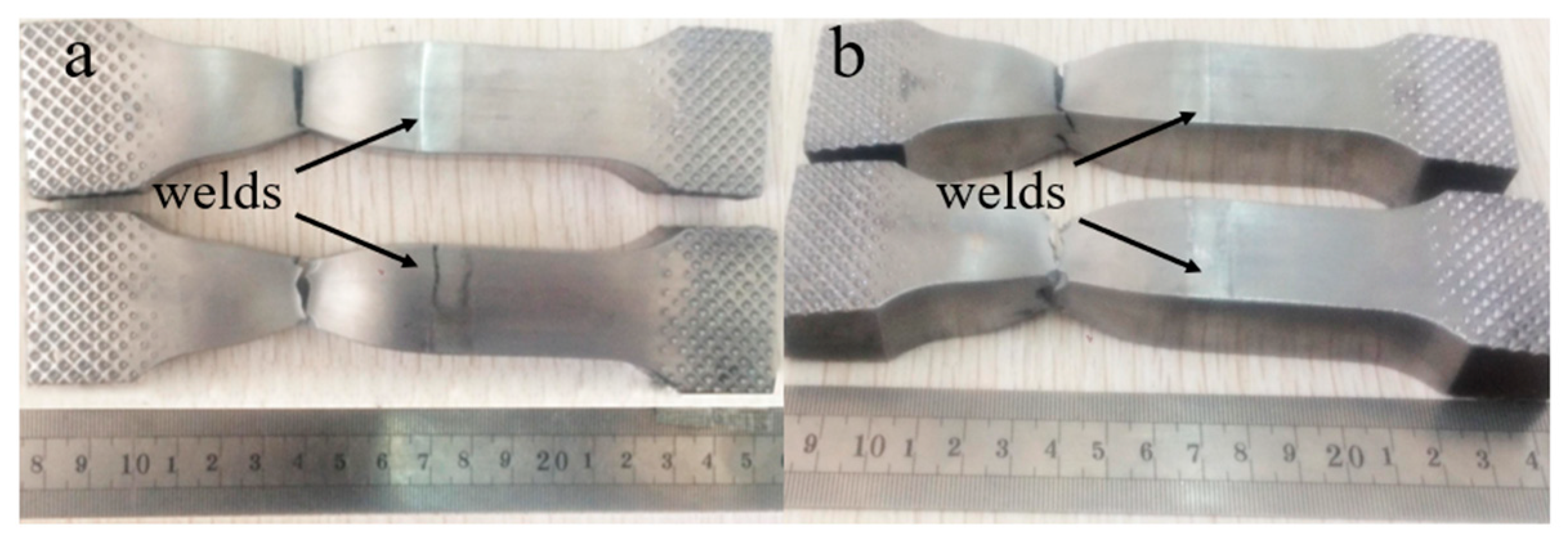
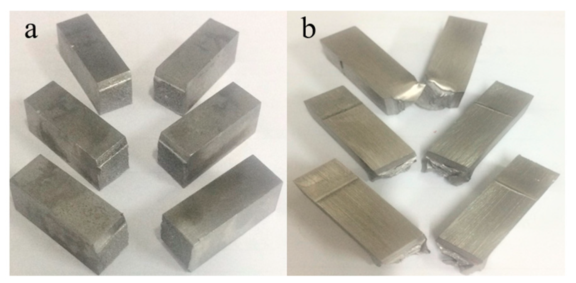
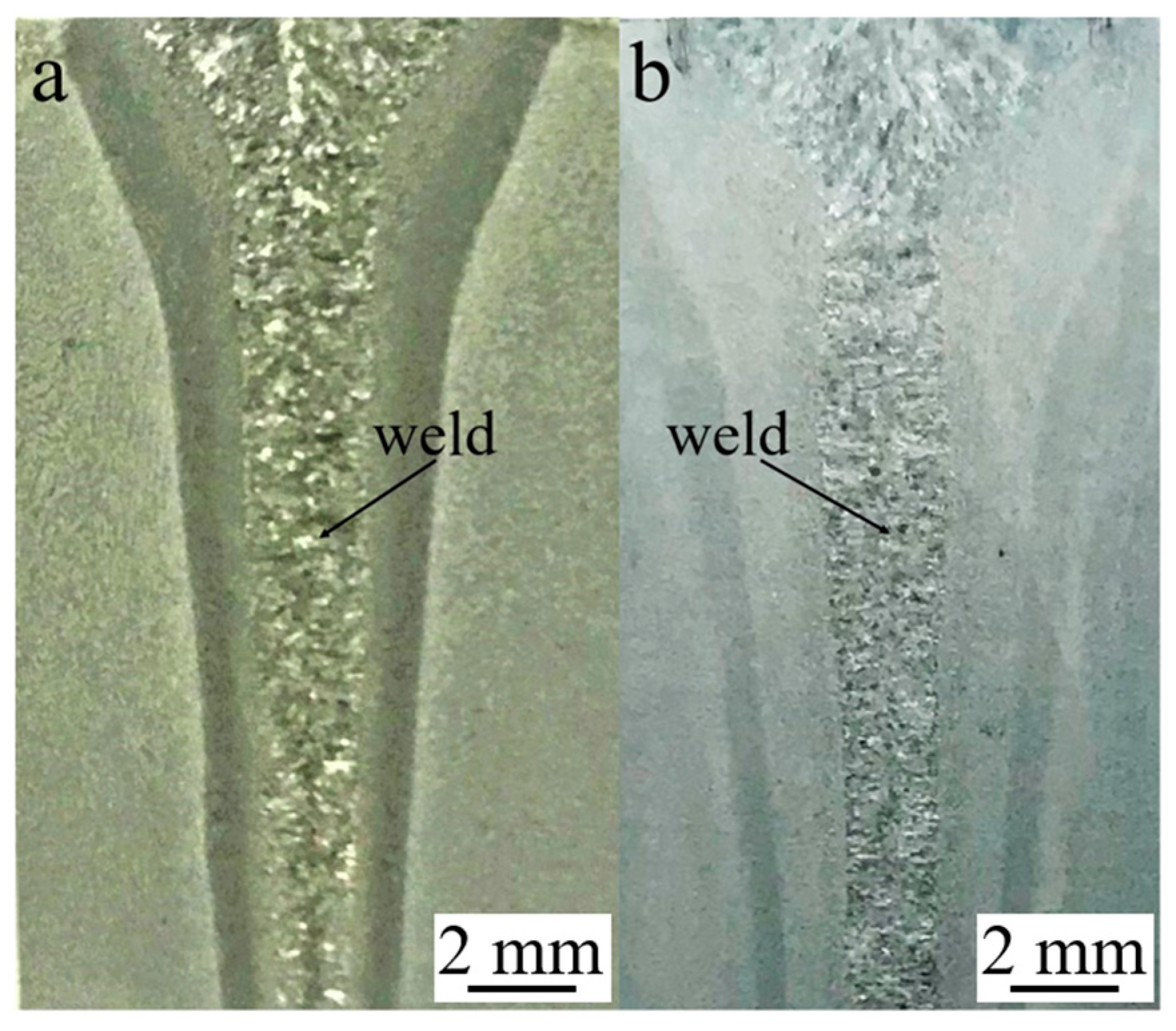
4.5. Properties of Electron Beam Welding (EBW) Joint

In order to study the effect of pre-heating and post-heating on the properties of the EBW joint, the microstructure and mechanical properties of the EBW joint were analyzed. Figure 14a,b is the tensile property analysis of the EBW joint, and Figure 15a,b is the impact property analysis of the EBW joint. It can be seen from Figure 14a,b that the fracture still occurs on the base metal after the tensile test of pre-heating and post-heating the EBW joint, which proves that the overall tensile strength is greater than that of the base metal. As can be seen from Figure 15a,b, the impact absorption energy of the EBW joint with only EBW are 13 MPa, 14 MPa, and 16 MPa, and the impact absorption energies of the EBW joint with pre-heating and post-heating are 16 MPa, 19 MPa and 19 MPa. Pre-heating and post-heating are equivalent to heat treatment of welded joints, so the structure is relatively uniform. The metallographic phase of the EBW joint is shown in Figure 16. Figure 16a shows the disposable EBW joint, and Figure 16b shows the EBW joint heated after pre-heating. As shown in Figure 16a, the maximum weld width of the joint after one-time welding is 6 mm. After pre-heating and post-heating, the maximum weld width is 8 mm (Figure 16b). However, the microstructure of the two kinds of welded joints is similar.

5. Conclusions

(1) In conclusion, different welding processes were tested and simulated, and the effects of different welding processes on the thermal cycle and deformation were compared and analyzed. At the same time, the residual stress was measured by using the blind hole method.
(2) Through the test and simulation results, it was found that the equivalent stress of the one-time welding process is greater than that of the pre-heating, welding, and post-heating processes. The test results are basically consistent with the simulation results near the weld, while the simulation results are greater than the test results on the base metal far away from the welds, and the reason is related to the release of residual stress.
(3) In the first welding process, the deformation of the test plate in X and Y directions is slightly less than that in the second welding process, and the deformation in the Z direction is slightly greater than that in the second welding process. In the future welding process, we will choose the second welding process. In addition, enough allowance will be left for welding transverse shrinkage.
(4) The mechanical properties and metallography of the EBW joint under different welding processes were compared and analyzed. The results showed that the tensile strength of the joints is greater than that of the base metal. The impact energy of the EBW joint after pre-heating and post-heating is higher, and the weld width is larger, but the metallographic structure of the joint is similar.

Author Contributions

Conceptualization, Y.Z. and J.W.; methodology, J.W. and Z.L. (Zhihong Liu); software, Z.L. (Zhihong Liu) and S.L.; validation, S.L., M.L. and Z.L. (Zhenfei Liu); formal analysis, M.L. and Z.L. (Zhenfei Liu); investigation, M.A. and S.L.; resources, J.M.; data curation, M.A. and J.M.; writing—original draft preparation, Y.Z.; writing—review and editing, Y.Z. and M.A.; visualization, Y.Z. and Z.L. (Zhenfei Liu); supervision, M.L.; project administration, M.L.; funding acquisition, J.W. All authors have read and agreed to the published version of the manuscript.

Funding

This work was supported by Comprehensive Research Facility for Fusion Technology Program of China under Contract (No. 2018-000052-73-01-001228) and National Key R&D. Program of China (Grant No. 2017YFE0300604, 2017YFE0300503).

Institutional Review Board Statement

Not applicable.

Informed Consent Statement

Not applicable.

Data Availability Statement

The data presented in this study are available on request from the corresponding author.

Acknowledgments

The authors are also grateful to the Hefei Juneng Electro Physics High-Tech Development Co. for their contribution to this research.

Conflicts of Interest

The authors declare no conflict of interest.

References

  1. Fang, J. Nuclear fusion energy-clean energy in the future. Sci. Technol. West. China 2012, 11, 55–56. [Google Scholar]
  2. Huang, Q.; Wu, Y.; Li, J.; Wan, F.; Chen, J.; Luo, G.; Liu, X.; Xu, Z.; Zhou, X.; Ju, X.; et al. Status and strategy of fusion materials development in China. J. Nucl. Mater. 2008, 30, 400–404. [Google Scholar] [CrossRef]
  3. Zheng, S.; Wu, Q.; Huang, Q.; Liu, S.; Han, Y. Influence of different cooling rates on the microstructure of the HAZ and welding CCT diagram of CLAM steel. Fusion Eng. Des. 2011, 86, 2616–2619. [Google Scholar] [CrossRef]
  4. Liu, S.; Li, X.; Ma, X.; Jiang, K.; Li, M.; Huang, K.; Lei, M.; DelNevo, A.; Agostini, P. Updated design of water-cooled breeder blanket for CFETR. Fusion Eng. Des. 2019, 146, 1716–1720. [Google Scholar] [CrossRef]
  5. Lei, M.; Wu, Q.; Xu, S.; Xu, K.; Ma, X.; Liu, S. Design and analysis of the equatorial inboard WCCB blanket module for CFETR. Fusion Eng. Des. 2020, 161, 111889. [Google Scholar] [CrossRef]
  6. Hu, J.; Jiang, Z.Z.; Huang, J.H.; Chen, S.H.; Zhao, X.K.; Zhang, H. Effects of heat treatment processes on microstructure and impact toughness of weld metal of vacuum electron beam welding on CLAM steel. J. Trans. China Weld. Inst. 2012, 33, 67–71. [Google Scholar]
  7. Hishinuma, A.; Kohyama, A.; Klueh, R.; Gelles, D.; Dietz, W.; Ehrlich, K. Current status and future R&D for reduced-activation ferritic/martensitic steels. J. Nucl. Mater. 1998, 258–263, 193–204. [Google Scholar] [CrossRef]
  8. Kano, S.; Yang, H.; McGrady, J.; Hamaguchi, D.; Ando, M.; Tanigawa, H.; Abe, H. Study of radiation-induced amorphization of M23C6 in RAFM steels under iron irradiations. J. Nucl. Mater. 2020, 533, 152088. [Google Scholar] [CrossRef]
  9. Dulieu, D.; Tupholme, K.; Butterworth, G. Development of low-activation martensitic stainless steels. J. Nucl. Mater. 1986, 141–143, 1097–1101. [Google Scholar] [CrossRef]
  10. Polekhina, N.A.; Litovchenko, I.Y.; Almaeva, K.V.; Bulina, N.V.; Korchagin, M.A.; Tyumentsev, A.N.; Chernov, V.M.; Leontyeva-Smirnova, M.V. Features of Phase Transformations of Low-activation 12%-Chromium Ferritic-Martensitic Steel Ek-181. Russ. Phys. J. 2020, 62, 2314–2318. [Google Scholar] [CrossRef]
  11. Rai, R.; Burgardt, P.; Milewski, J.O.; Lienert, T.J.; DebRoy, T. Heat transfer and fluid flow during electron beam welding of 21Cr–6Ni–9Mn steel and Ti–6Al–4V alloy. J. Phys. D Appl. Phys. 2009, 42, 025503. [Google Scholar] [CrossRef]
  12. Huang, Q.; Li, C.; Li, Y.; Chen, M.; Zhang, M.; Peng, L.; Zhu, Z.; Song, Y.; Gao, S. Progress in development of China low activation martensitic steel for fusion application. J. Nucl. Mater. 2007, 367–370, 142–146. [Google Scholar] [CrossRef]
  13. Li, C.; Huang, Q.; Wu, Q.; Liu, S.; Lei, Y.; Muroga, T.; Nagasaka, T.; Zhang, J.; Li, J. Welding techniques development of CLAM steel for test blanket module. Fusion Eng. Des. 2009, 84, 1184–1187. [Google Scholar] [CrossRef]
  14. Zhang, X.L.; Li, R.F.; Liu, Q.Z.; Du, H.H. Welding procedure test of P91 heat resistant steel. Metalworking (Hot Work) 2011, 16, 39–41. [Google Scholar]
  15. Sun, X.; Wang, H.H. Martensite in weld metal of new heat resistant steel P91. Welding 2010, 4, 7–12. [Google Scholar]
  16. Lindau, R.; Klimenkov, M.; Jäntsch, U.; Möslang, A.; Commin, L. Mechanical and microstructural characterization of electron beam welded reduced activation oxide dispersion strengthened—Eurofer steel. J. Nucl. Mater. 2011, 416, 22–29. [Google Scholar] [CrossRef]
  17. Jiang, Z.; Huang, J.; Chen, S.; Ju, X. Microstructure transformation and mechanical properties of electron beam welded joints of fusion CLAM steel. Trans. China Weld. Inst. 2011, 32, 45–48. [Google Scholar]
  18. Lundback, A.; Runnemalm, H. Validation of three-dimensional finite element model for electron beam welding of Inconel 718. Sci. Technol. Weld. Join. 2013, 10, 717–724. [Google Scholar] [CrossRef]
  19. Li, C.W.; Wang, Y. Three-dimensional finite element analysis of temperature and stress distributions for in-service welding process. Mater. Des. 2013, 52, 1052–1057. [Google Scholar] [CrossRef]
  20. Lacki, P.; Adamus, K. Numerical simulation of the electron beam welding process. Comput. Struct. 2011, 89, 977–985. [Google Scholar] [CrossRef]
  21. Kiyoshima, S.; Deng, D.; Ogawa, K.; Yanagida, N.; Saito, K. Influences of heat source model on welding residual stress and distortion in a multi-pass J-groove joint. Comput. Mater. Sci. 2009, 46, 987–995. [Google Scholar] [CrossRef]
  22. Kim, Y.-C.; Hirohata, M.; Inose, K. FEM Simulation of Distortion and Residual Stress Generated by High Energy Beam Welding with Considering Phase Transformation. Open J. Met. 2014, 4, 31–39. [Google Scholar] [CrossRef] [Green Version]
  23. Joshi, S.; Hildebrand, J.; Aloraier, A.S.; Rabczuk, T. Characterization of material properties and heat source parameters in welding simulation of two overlapping beads on a substrate plate. Comput. Mater. Sci. 2013, 69, 559–565. [Google Scholar] [CrossRef]
  24. Bonakdar, A.; Molavi-Zarandi, M.; Chamanfar, A.; Jahazi, M.; Firoozrai, A.; Morin, E. Finite element modeling of the electron beam welding of Inconel-713LC gas turbine blades. J. Manuf. Process. 2017, 26, 339–354. [Google Scholar] [CrossRef]
  25. Anca, A.; Cardona, A.; Risso, J.; Fachinotti, V.D. Finite element modeling of welding processes. Appl. Math. Model. 2011, 35, 688–707. [Google Scholar] [CrossRef]
  26. Davis, J.W.; Smith, P.D. ITER Materials Properties Handbook (MPH); ITER Doc. G 74 MA 16 04-05-07 R0.1 (Internal Project Document Distributed to the ITER Participants); U.S. Department of Energy Office of Scientific and Technical Information: Oak Ridge, TN, USA, 1996.
  27. Fu, P.; Mao, Z.; Zuo, C.; Wang, Y.; Wang, C. Microstructures and fatigue properties of electron beam welds with beam oscillation for heavy section TC4-DT alloy. Chin. J. Aeronaut. 2014, 27, 1015–1021. [Google Scholar] [CrossRef] [Green Version]
  28. Xia, X.; Wu, J.; Liu, Z.; Shen, X.; Ma, J.; Liu, Z. Study of microstructure difference properties of electron beam welds with beam oscillation of 50 mm 316L in CFETR. Fusion Eng. Des. 2019, 138, 339–346. [Google Scholar] [CrossRef]
  29. Mathar, J. Determination of inherent stress by measuring the deformations around drilled holes. Tech. Rep. Arch. Image Libr. 1934, 56, 245–254. [Google Scholar]
  30. Tian, Y.; Wang, C.; Zhu, D.; Zhou, Y. Finite element modeling of electron beam welding of a large complex Al alloy structure by parallel computations. J. Mater. Process. Technol. 2008, 199, 41–48. [Google Scholar] [CrossRef]
  31. Goldak, J.; Chakravarti, A.; Bibby, M. A new finite element model for welding heat sources. Metall. Trans. Trans. A 1984, 15, 299–305. [Google Scholar] [CrossRef]
  32. Wu, H.; Feng, J.; He, J.; Zhang, B. Three-dimensional calculation of temperature and stress field in Al-Li alloy during electron beam welding by finite element analysis. Weld. Tech. 2004, 6, 10–12. [Google Scholar]
Figure 1. Direct-reading of the spectrometer.
Jne 02 00021 g001
Figure 2. The experimental equipment of electron beam welding (EBW).
Jne 02 00021 g002
Figure 3. Welding method of test plate.
Jne 02 00021 g003
Figure 4. Sketch of EBW with beam oscillation [27]. (a) Oscillation with electromagnetic fields, (b) beam oscillating welding, (c) wave function. Reprinted with permission from [27], 2014, Elsevier.
Jne 02 00021 g004
Figure 5. Stress measurement by blind hole method.
Jne 02 00021 g005
Figure 6. Finite element model. (a) finite element model of one time welding, (b) finite element model of pre-heating, welding and post heating.
Jne 02 00021 g006
Figure 7. Boundary conditions of finite element model. (a) one time welding, (b) pre-heating, welding, and post-heating.
Jne 02 00021 g007
Figure 8. Heat source check. (a) heat source checking plate, (b) simulated welding temperature, (c) deformation in the X-direction, (d) deformation in the Y-direction, and (e) deformation in the Z-direction.
Jne 02 00021 g008
Figure 9. Front view of test panel.
Jne 02 00021 g009
Figure 10. Temperature changes with time at points A, B, C, D, E and F. (a) one time welding, (b) pre-heating, welding, and post-heating.
Jne 02 00021 g010
Figure 11. Diagram of residual stress. (a) strain gauge distribution, (b) one-time welding, (c) preheating, welding, and post-heating.
Jne 02 00021 g011
Figure 12. Equivalent stress. (a) one-time welding, (b) pre-heating, welding and post-heating.
Jne 02 00021 g012
Figure 13. Welding deformation. (ac) the deformation of the first welding method in X, Y, and Z-directions, (df) the deformation of the second welding method in X, Y, and Z directions.
Jne 02 00021 g013
Figure 14. Tensile samples. (a) Tensile samples for one time welding. (b) Tensile samples for pre-heating, welding and post-heating.
Jne 02 00021 g014
Figure 15. Impact samples. (a) Impact samples for one time welding. (b) Impact samples for pre-heating, welding and post-heating.
Jne 02 00021 g015
Figure 16. Microstructure of EBW joint. (a) Microstructure for one time welding. (b) Microstructure for pre-heating, welding and post-heating.
Jne 02 00021 g016
Table 1. Chemical composition of reduced activated ferrite/martensite (RAFM) steels (wt%).
CrCWVTaMnSiONPTi
8.960.0931.480.160.100.480.042<0.01<0.02<0.005<0.01
Table 2. RAFM steels properties used in the simulation.
Temperature
(K)
Specific Heat
(J/(kg K))
Thermal Conductivity
(W/(m K))
Coefficient of Thermal Expansion (10−6/K)Yang’s Modulus
(GPa)
298443.817.711.8214.7
373474.018.912.0211.2
473512.420.912.4205.2
673608.724.613.1187.3
873803.226.513.8162.6
1073785.427.214.6133.6
1273623.329.415.3103.2
1473658.331.816.074.5
1673885.333.716.750.6
Table 3. Welding parameters.
Voltage
Ua (kV)
Beam Current
Ib (A)
Focusing
Current If (A)
Velocity
V (m/s)
Working Distance (m)Oscillation ShapeOscillation Frequency
fp (Hz)
1500.052.4480.0050.42circular500
Publisher’s Note: MDPI stays neutral with regard to jurisdictional claims in published maps and institutional affiliations.

