Abstract
Characterization of surface integrity is possible with three critical metrics: microstructure, surface roughness, and residual stress. The latter two are discussed in this paper for low-alloyed aluminum material quality. Ball burnishing is a regularly used finishing procedure to improve surface roughness, shape accuracy, and fatigue life, taking advantage of the fact that it can favorably influence the variation in stress conditions in the material. The effect of burnishing is investigated using finite element simulation with DEFORM 2D software using the real surface roughness of the workpiece. The FEM model of the process is validated with experimental tests, the surface roughness is measured using an AltiSurf520 measuring device, and the residual stress is analyzed with a Stresstech Xstress 3000 G3R X-ray diffraction system (Stresstech, Vaajakoski, Finland). The results indicate that the burnishing process improves the surface roughness and stress conditions of AlCu6BiPb low-alloyed aluminum, and the study shows that there is good agreement between the FE and experimental results, further revealing the effect of the process parameters on the distribution of the compressive residual stress.
1. Introduction
It is well known that the fatigue life of structures is greatly influenced by the quality of the surface, which is why great attention is paid to the specification and finish of the surfaces of machined parts in a time-effective, cost-effective, and environmentally friendly way. This is supported by the research work of Sztankovics and Varga [1] on FEM investigation of burnishing or the work of Suraratchai et al. on surface roughness modelling [2]. Surface integrity can be manipulated by the application of different mechanical surface techniques like burnishing [3,4], which is a cold plastic deformation process with many advantageous properties. For example, Kato et al. demonstrated in their research that the process improves surface characteristics [5]. Skoczylas et al. also proved this through 3D roughness parameters [6]. Luo et al. [7] and El-Axir et al. [8] addressed the beneficial effect of the process on surface hardness. Besides this, Schubnell et al. studied the influence of burnishing on stress conditions [9]. In addition to experimental tests, Posdzich et al. also verified the beneficial effect of burnishing on the residual stress with simulations [10], just like Amini et al., who used real surface roughness as a basis for modeling [11]. But still, most of the studies related to the burnishing procedure have aimed at the implementation of experimental tests to optimize parameters such as force, feed rate, speed, etc., which have influence on surface structure. However, finite element simulation of this finishing process has increasingly attracted the attention of researchers and engineers because—among other things—it reduces the high costs and time of experimental tests.
This fact was also highlighted by Saldana-Robles et al. in their research, in which a 3D FE model with random roughness was developed in the ANSYS program to analyze surface roughness after burnishing, residual stress values, and their depths on cylindrical specimens of AISI 1045 steel [12]. Aldrine et al. also investigated the residual stress caused by burnishing, but on flat aluminum alloy surfaces (Al2024-T351 and Al7075-T651). In their model, the tool is treated as a rigid body, while the workpiece undergoes an elastic–plastic deformation for which a bilinear isotropic hardening material model is applied [13]. The approach of their study and its results are intriguing, but not validated by experiments. In the study of Kuznetsov et al., the tool was also modeled as a rigid body, but they used the elasto-plastic Johnson–Cook model to describe the workpiece material (AISI 52100 hardened steel) in ABAQUS software. The aim of their work was to determine the parameter settings that most favorably affect the micro-hardness and roughness of the machined surface [14]. The model created by Chaudhary et al. was also assembled in ABAQUS to determine the influence of burnishing feed using so-called multi-path simulation. In their study—despite the fact that they mainly investigated the change in residual stress—an isotropic hardening material model was used [15].
Among the burnishing parameters, Qi et al. highlighted the effect of burnishing force on surface roughness and first developed a theoretical model based on Hertzian theory, which was then used to construct a finite element simulation [3]. Charfeddine et al. also used Hertzian theory to construct a finite element model to determine the penetration depth of the tool, but they pointed out that the theory can only be applied correctly in a modified form, as the material of the workpiece reaches the plastic deformation zone during the burnishing process [16].
In this investigation, a 2D FEM model for the ball-burnishing process is established to examine the effect of the process on surface roughness and stress conditions. The created finite element model is an improved model for low-alloyed aluminum workpiece materials by the authors [17,18] using the study cited in [19].
2. Materials and Methods
Due to its low density and favorable mechanical properties, the machinability of aluminum and its alloys is increasingly important, as evidenced by the fact that many industrial areas use them for the material quality of their products and components [20,21,22,23]. However, the machining of these material qualities with conventional chip removal technologies also presents problems in terms of surface roughness (e.g., due to the effect of tool edge geometry [24]) and residual stress (e.g., grinding leaves metallurgical defects in physical structures [25]).
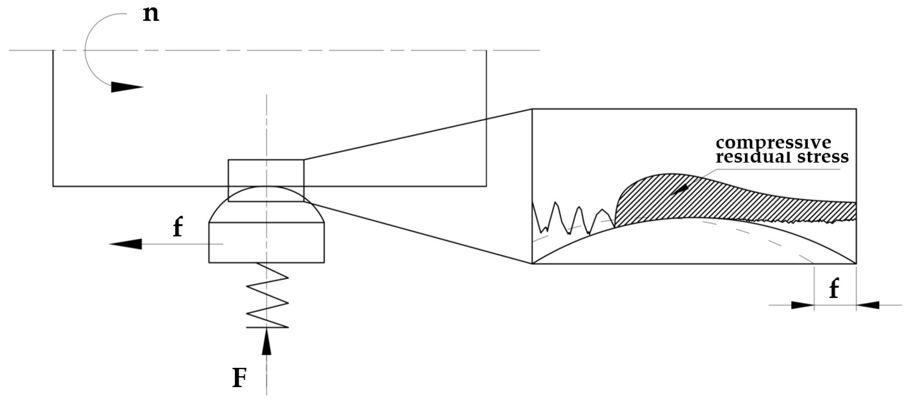
To eliminate these unfavorable effects, surface burnishing can be effectively applied, which is a chipless, environmentally friendly process performed below the recrystallization temperature. External cylindrical surfaces can be burnished on universal or CNC lathes. A schematic illustration of the process with motion conditions can be seen in Figure 1.
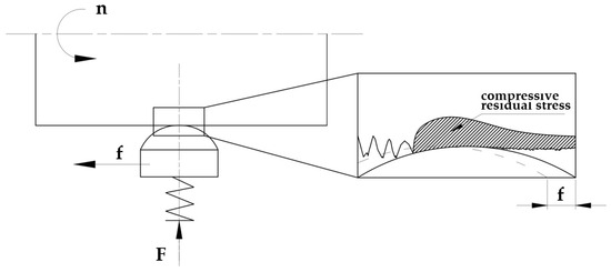
Figure 1.
Schematic illustration of burnishing treatment. n—revolution; f—feed rate; F—burnishing force.
With the help of the spring built into the tool, a suitable burnishing force—exceeding the yield strength of the workpiece material—can be created, and then the burnishing tool is fed in a straight line along the surface of the rotating workpiece with the feeding at a given rate.
As evidenced by the literature presented so far, several prominent experimental studies have investigated this method, but it should be noted that numerical simulation and modeling can be used as a faster way to understand the behavior of the materials and the processes that take place within them [26]. Using different numerical simulation techniques, researchers can gain insight into complex material responses, and this information can be used to develop constitutive models that accurately represent the material’s behavior, which is key in industrial fields like aerospace or automotive engineering.
In this investigation, the FE models of the diamond burnishing process were simulated by the DEFORM FE code as 2D simulations, because they are significantly more cost- and time-effective than the 3D versions. The simulation model included a top die as the master surface—in this case, it was the burnishing tool, as a rigid sphere with a 3.5 mm radius—and a slave surface, which was the real initial surface of the workpiece. For the subsequent validation process, the real unburnished workpiece was measured on a 4 mm long distance with an Altisurf 520 topography-measuring device, and the surface points were imported into the code as x-y coordinates. Since the results of preliminary theoretical and experimental studies, as well as the reviewed literature, show that the method works at a depth of 0.02–0.17 mm [27,28], I simplified the workpiece’s thickness to 0.2 mm to reduce the calculation time. The material grade of the workpiece (AlCu6BiPb) was selected from the system library, and due to the nature of the machining, it was modeled as an elastic–plastic object. To describe small deformations caused by burnishing, the points of the flow curve corresponding to the material quality must be approximated by a function in finite element space. In the simulations, the “power-law” relation provided by the program was used to define the variable yield stress. Formula 1 describes yield stress with deformation, where is the flow stress.
An overview of the material model used is given in Table 1.

Table 1.
Parameters of elastic–plastic material modelling.
Compared to previously created models in which isotropic hardening was used [17,18], in this model, so-called iso-kinematic hardening was used for the workpiece material, which is also known as mixed hardening, and its setting allows for a more realistic behavior of the residual stress than simple kinematic hardening.
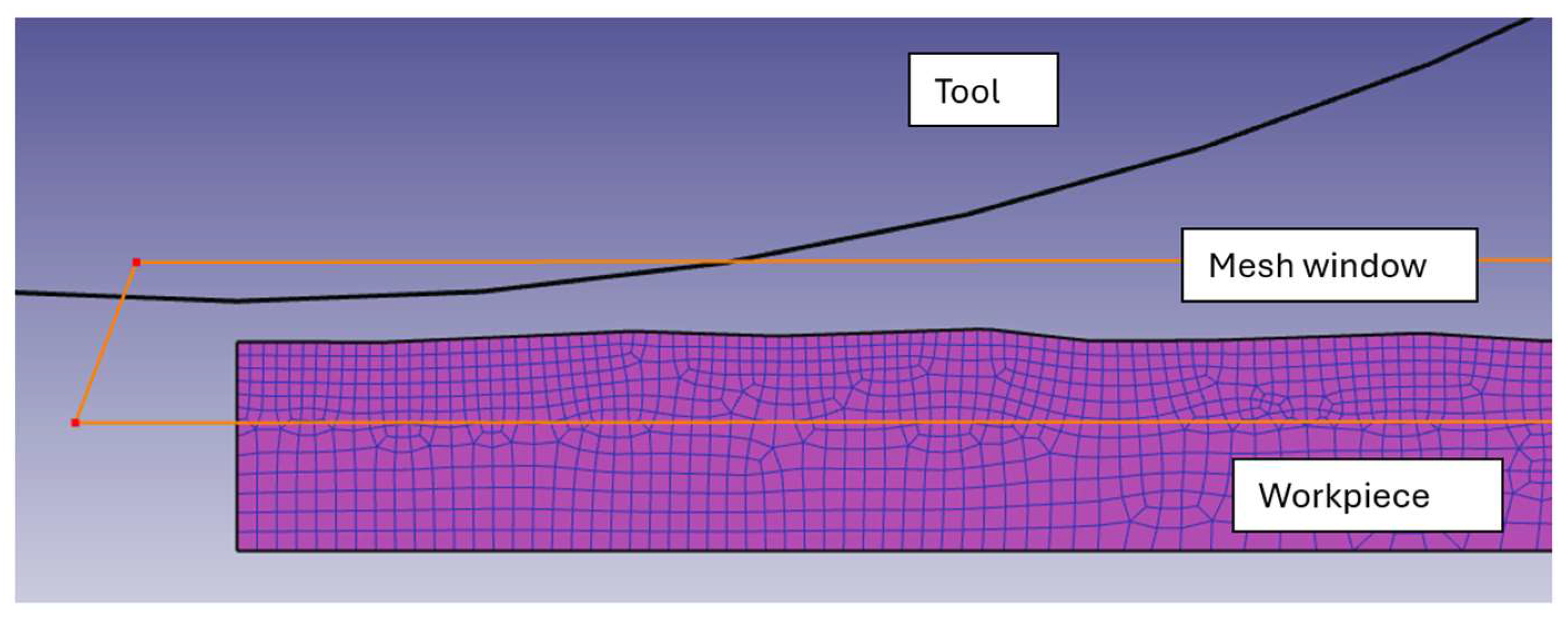
The mesh for the model was generated using the automatic meshing tool available in DEFORM 2D. The workpiece mesh had 6397 elements with 6886 nodes, and a mesh window was used to refine the elements along the expected contact area, as illustrated in Figure 2.
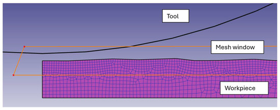
Figure 2.
A section of the FEM model.
In the simulation, the workpiece was fixed at the bottom. Based on the experience of previous FE studies, to avoid convergence errors, remeshing criteria were set for the interference depth and maximum step increment of this model. In the previous models [17,18], during the simulation of the movement, the tool loaded the surface of the workpiece with a specific force and then slid along it in a straight line, but in this study, the motion was adapted to two-dimensional conditions. The motion characteristic of the process was simulated by defining path type movement, where initially, the tool moved down vertically until it reached the precalculated indentation depth, then moved to the initial position. Next, the tool horizontally moved with the displacement value of the burnishing feed and loaded the surface of the workpiece again. The whole cycle was repeated 10 times. I calculated the tool penetration depth theoretically using the modified Hertzian theory, considering Ponomarjov’s point of view. The details of this can be found in [19].
Theoretical studies were followed by physical experiments because the results of these can be used as baseline data to validate the simulation. My burnishing experiments were executed with an OPTIMUM type OPTIturn S600 CNC lathe (Figure 3a) with a PCD spherical burnishing tool (r = 3.5 mm). The kinematic viscosity of the manual dosed oil was υ = 70 mm2/s. This operation was preceded by a finishing turning set at f1t = 0.2 and then an f2t = 0.15 mm/rev feed rate.

Figure 3.
Implementation of machining and measuring processes: (a) the burnishing process; (b) measuring of surface roughness; (c) measuring of residual stress.
Measurements of the surface roughness before and after burnishing were conducted on an Altisurf 520 measuring device with a CL2 confocal chromatic sensor (Figure 3b). For the evaluation of the data, a cut-off λc = 0.8 mm and Gauss filter were applied. The valid standard of geometrical product specifications (GPS) is ISO 22081:2021.
I similarly measured the residual stress on the workpiece with the X-ray diffraction measuring method, which is a commonly used measuring technique, and in some cases, it can also be used to examine the depth of residual stress. For example, Qian et al. combined it with the chemical etching method to measure residual stress at different depths of the material [29].
In this experiment, non-destructive tests were realized with an Stresstech Xstress 3000 G3R (Figure 3c) diffractometer using Xtronic software and the following equation, which is called the Bragg equation [30]:
where:
- ➢
- n is the integer determined by the order given;
- ➢
- λ is the wave-length of the X-ray;
- ➢
- dhkl is the spacing between the planes in the atomic lattice;
- ➢
- Θ is the angle between the incident ray and the scattering planes.
The equipment was developed for direct residual stress measurement, during which the X-ray tube and the detector system were tilted over the sample at rest. The measuring process was performed in 5–9 tilt positions, with a beam spot diameter of 1–3 mm, in both the tangential and axial directions, as it was assumed that the direction of the processing would have an influence on the changing of the stress conditions. However, in the following section, I will only consider the residual stress in the axial direction, since I simplified the process to 2D in the FEM simulation.
Table 2 summarizes the parameters set during burnishing, as well as the results of the previous measurement tests.

Table 2.
The initial values of the theoretical and experimental tests.
3. Results
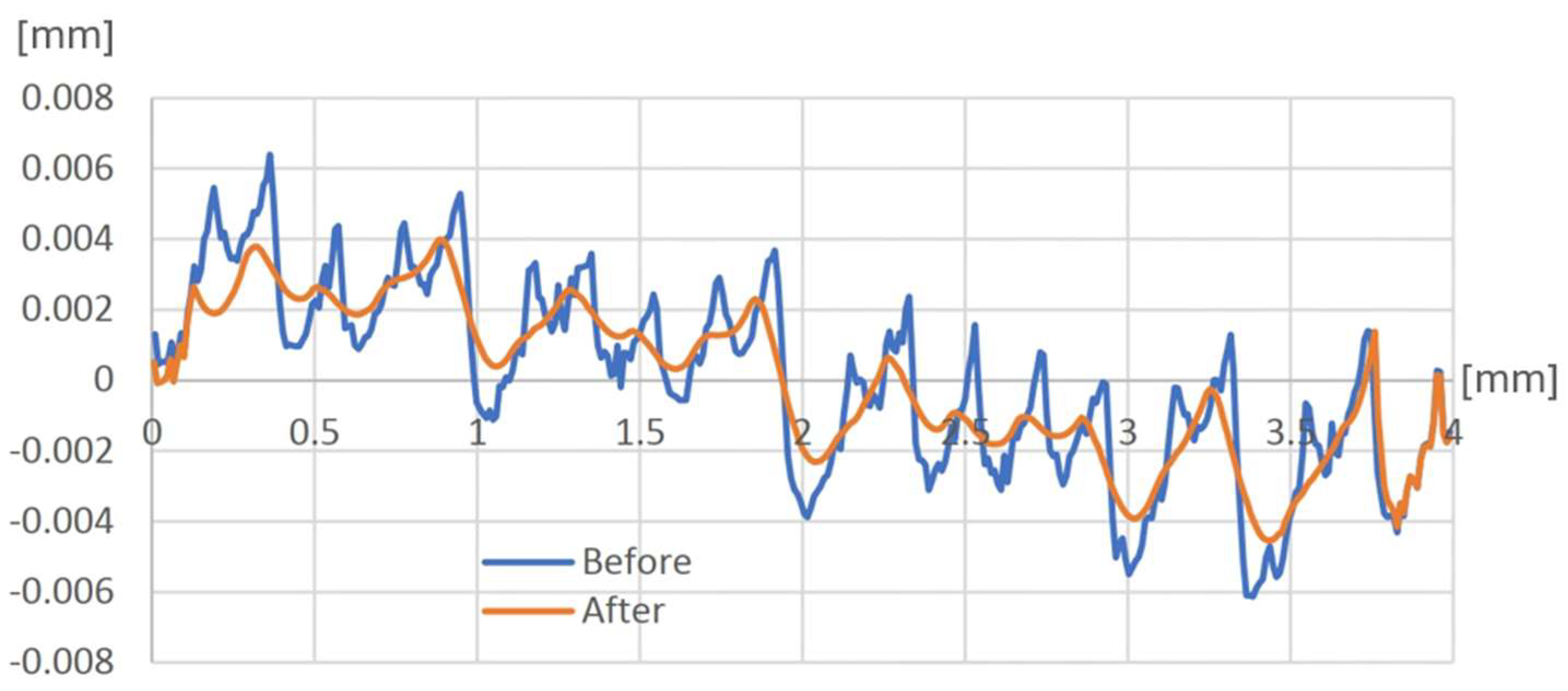
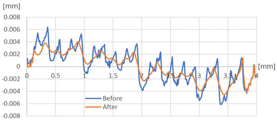
Among the evaluations, I first present the change in surface roughness caused by burnishing and compare the theoretical and experimental values. After running the simulation, the problem arose that the meshing distorted the original surface roughness (and thus the subsequent result), so it was necessary to remesh the workpiece with a larger number of elements and nodes. Due to this remeshing, the surface roughness changed from the physically measured 1.478 µm to 1.457 µm. In the DEFORM software, as the coordinates of the profile points can be inserted, they can be collected in a text/Excel file and the roughness parameters can be determined by applying the appropriate formulae. Scheme 1 shows the difference in the average surface roughness in millimeters between the turned meshed surface (before burnishing) and the burnished surface after running the simulation.
Scheme 1.
Change in the surface profile after simulation.
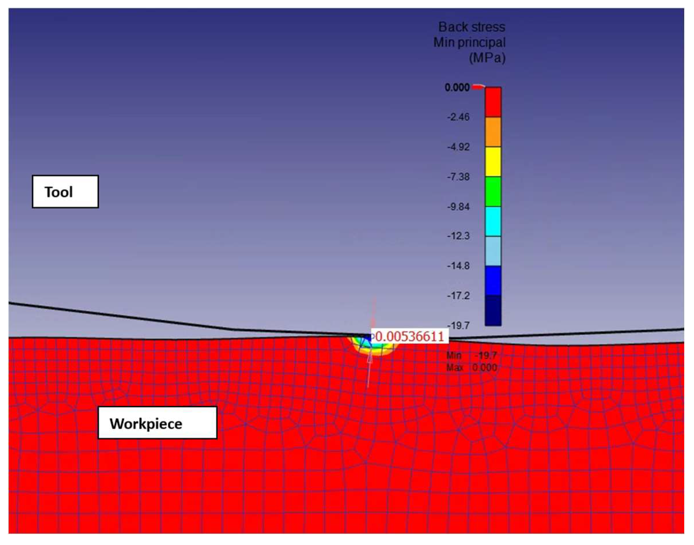
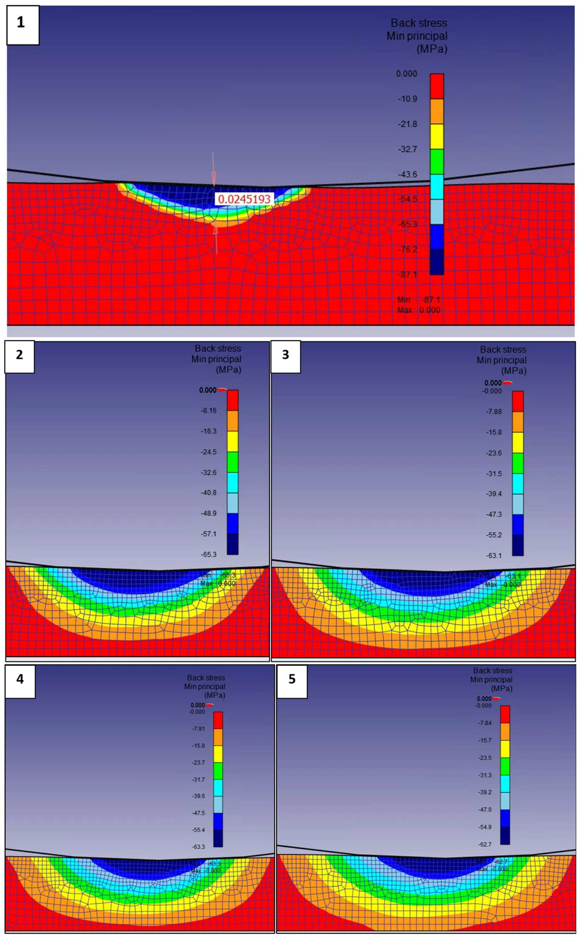
For the examination of residual stress, the configuration shown in Figure 4 was used for the evaluation of the simulation, where the first contact between the tool and the workpiece can be seen with the resulting compressive residual stress and its depth.
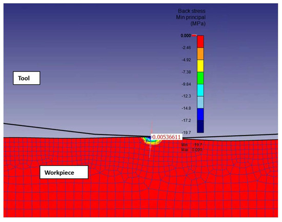
Figure 4.
Changing of stress conditions during the first contact.
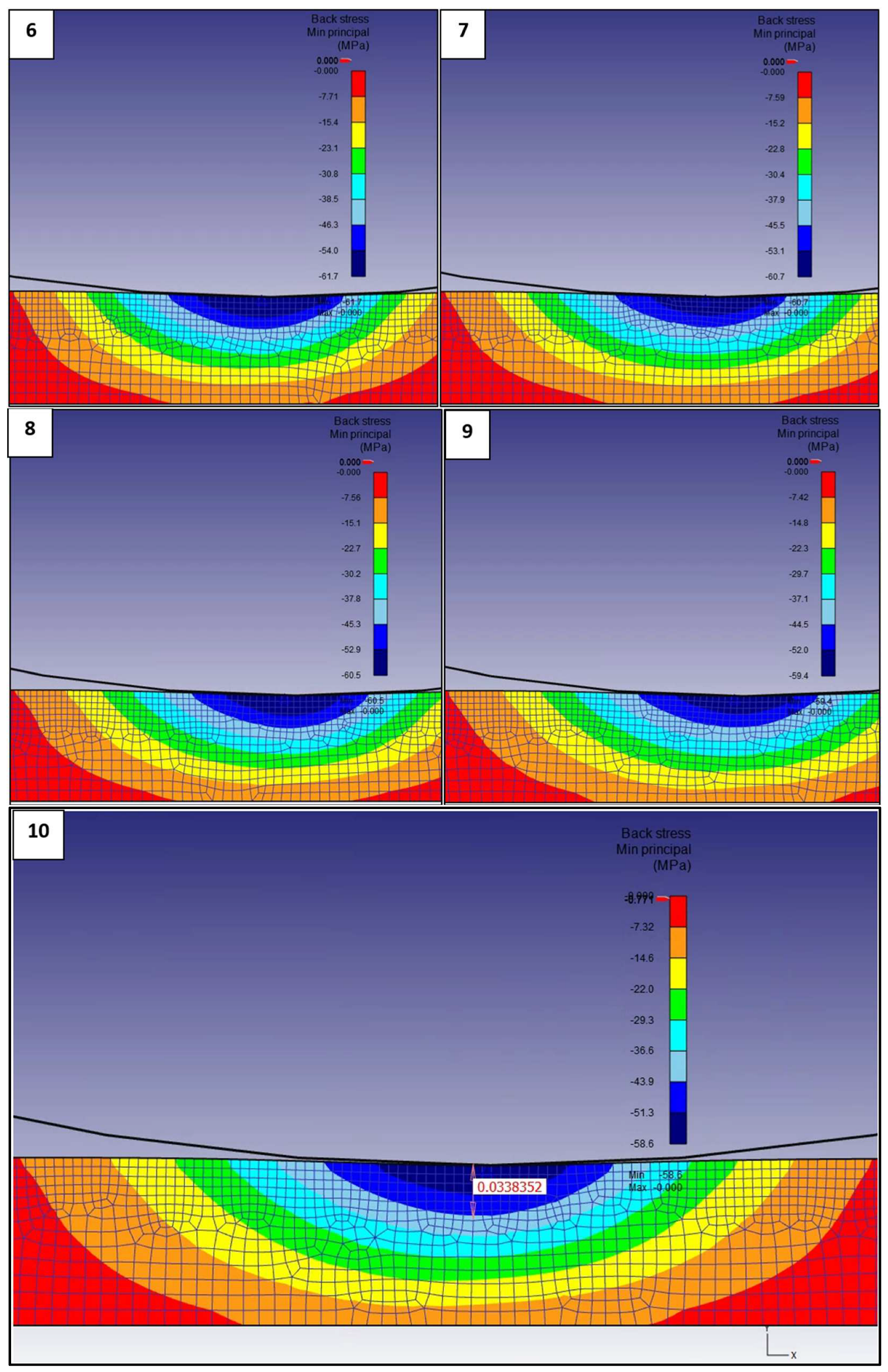
As was mentioned, the process of “loading-unloading-displacement” was repeated 10 times, and Figure 5 shows the distribution of the minimum principal residual stress for each full loaded step according to the 0.001 mm step.
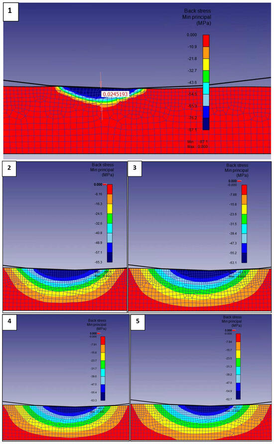
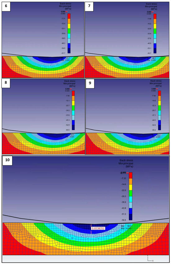
Figure 5.
Changing of stress conditions for the 10 full loaded steps.
The figures show not only the numerical value of the generated residual stress, but also the depth and distribution, which must be highlighted separately in the case of the first and tenth steps.
4. Discussion and Conclusions
This paper presents finite element modeling of diamond burnishing based on the measurement of the roughness of a previously turned surface. The aim of the study was to theoretically and experimentally examine the influence of the burnishing process on the changing of the surface roughness and stress conditions of a low-alloyed aluminum workpiece. The simulation of burnishing was performed with the DEFORM 2D FE code, in which the tool was modeled as a rigid body and the surface of the workpiece as an elastic–plastic object using the iso-kinematic hardening rule. The real process was carried out with an OPTIMUM type OPTIturn S600 CNC lathe, with a PCD spherical tool and manually dosed oil. Before and after the experiment, non-destructive X-ray residual stress analysis was performed using a Stresstech Xstress 3000 G3R diffractometer, while measurements of surface roughness were executed using an Altisurf 520 measuring device.
The results from the simulations were compared with the experimental data to determine the convergence of the solution, and based on this, the following conclusions can be drawn:
- The value obtained during the theoretical determination of the indentation depth of the tool—which is of key importance—was 2.34 µm, while in the real case, it was 3.62 µm. The two results come close enough to form the basis for further theoretical and experimental investigations.
- Correct modeling of surface roughness requires a high number of elements and nodes in the mesh, which significantly increases the calculation time, but it is still possible and preferable to model the process in two dimensions than in 3D. The numerical results of the realized experiment and the simulation are summarized in Table 3.
 Table 3. Numerical results of arithmetical mean roughness (Ra).
 - The results of the X-ray diffraction measurements showed that the burnished surface had a compressive residual stress between (−88.6) and (−138.6) MPa. Comparing these values with the FEM simulation results, where this range was between (−58.6) and (−87.1) MPa, it can be observed that these values were the same only for the first tool penetration. One possible explanation for this may be that different remeshing criteria should be set and/or the material quality should not be selected from the software library, but should also be set to its real parameter values on the basis of a preliminary yield strength examination.
- One of the advantages of FEM is that it provides information on the residual stress distribution, and it can be seen that the minimum (and preferred) value of residual stress at the first contact between the tool and the workpiece was 0.005366 mm, increasing to 0.03383 mm at the end of the machining (Figure 5);
- In relation to the former statement, it can also be stated that the distribution of residual stress is more characteristic at a greater depth than expected, so it is necessary to extend the thickness of the workpiece to a greater value during the simulation.
- The values of the residual stress vary unfavorably as it relaxes excessively, which leads to the conclusion that the value of the burnishing feed rate is too low. This is significant because, by increasing this parameter setting, time and cost can be saved in terms of both real burnishing and simulation calculations.
- Based on the results obtained so far, it may be considered that it is preferable to test the finite element simulation of the process for surface roughness and residual stress conditions separately, and then the effect of a higher feed rate should be investigated.
Funding
This research received no external funding.
Institutional Review Board Statement
Not applicable.
Informed Consent Statement
Not applicable.
Data Availability Statement
The original contributions presented in the study are included in the article, further inquiries can be directed to the corresponding author.
Conflicts of Interest
The author declare no conflict of interest.
Correction Statement
This article has been republished with a minor correction to the reference 26. This change does not affect the scientific content of the article.
References
- Sztankovics, I.; Varga, G. FEM analysis of the burnishing process of X5CrNi18-10 stainless steel. Cut. Tools Technol. Syst. 2022, 97, 137–144. [Google Scholar]
- Suraratchai, M.; Limido, J.; Mabru, C.; Chieragatti, R. Modelling the influence of machined surface roughness on the fatigue life of aluminium alloy. Int. J. Fatigue 2008, 30, 2119–2126. [Google Scholar] [CrossRef]
- Qi, B.; Huang, X.; Guo, W.; Ren, X.; Chen, H.; Chen, X. A novel comprehensive framework for surface roughness prediction of integrated robotic belt grinding and burnishing of Inconel 718. Tribol. Int. 2024, 195, 109574. [Google Scholar] [CrossRef]
- Chomienne, V.; Valiorgue, F.; Verdu, C. Influence of ball burnishing on residual stress profile of a 15-5PH stainless steel. CIRP J. Manuf. Sci. Technol. 2016, 13, 90–96. [Google Scholar] [CrossRef]
- Kato, H.; Ueki, H.; Yamamoto, K.; Uasunaga, K. Wear resistant improvement by nanostructured surface layer produced by burnishing. Mater. Sci. Forum 2018, 917, 231–235. [Google Scholar] [CrossRef]
- Skoczylas, A.; Zaleski, K. Selected properties of the surface layer of C45 steel parts subjected to laser cutting and ball burnishing. Materials 2020, 13, 3429. [Google Scholar] [CrossRef]
- Luo, H.; Liu, J.; Wang, L.; Zhong, Q. The effect of burnishing parameters on burnishing force and surface microhardness. Int. J. Adv. Manuf. Technol. 2006, 28, 707–713. [Google Scholar] [CrossRef]
- El-Axir, M.H.; Othman, O.M.; Abodiena, A.M. Improvements in out-of-roundness and micro-hardness of inner surfaces by internal ball burnishing process. J. Mater. Process. Technol. 2008, 196, 120–128. [Google Scholar] [CrossRef]
- Schubnell, J.; Farajian, M. Fatigue improvement of aluminum welds by means of deep rolling and diamond burnishing. Weld. World 2022, 66, 699–708. [Google Scholar] [CrossRef]
- Posdzich, M.; Stöckmann, R.; Morczinek, F.; Putz, M. Investigation of a plain ball burnishing process on differently machined AluminiumEN AW 2007 surfaces. MATEC Web Conf. 2018, 190, 11005. [Google Scholar] [CrossRef]
- Amini, C.; Jerez-Mesa, R.; Travieso-Rodriguez, J.A.; Lluma, J.; Estevez-Urra, A. Finite element analysis of ball burnishing on ball-end milled surfaces considering their original topology and residual stress. Metals 2020, 10, 638. [Google Scholar] [CrossRef]
- Saldana-Robles, A.; Aguilera-Gomez, E.; Plascencia-Mora, H.; Ledesma-Orozco, E.; Reveles-Arredondo, J.; Saldana-Robles, N. FEM burnishing simulation including roughness. Mechanik 2015, 2, 79–91. [Google Scholar] [CrossRef][Green Version]
- Aldrine, M.E.; Mahendra Babu, N.C.; Anil Kumar, S. Evaluation of induced residual stresses due to low plasticity burnishing through finite element simulation. AMMMT 2017, 4, 10850–10857. [Google Scholar] [CrossRef]
- Kunetsov, V.; Smolin, I.; Skorobogatov, A.; Akhmetov, A. Finite element simulation and experimental investigation of nanostructuring burnishing AISI 52100 steel using an inclined flat cylindrical tool. Appl. Sci. 2023, 13, 5324. [Google Scholar] [CrossRef]
- Chaudhary, A.; Kumar Baral, S.; Tiwari, G.; Dumpala, R. Finite element analysis of ball burnishing: Evolution of residual stresses and surface profile in Ti-6Al-7Nb alloy. Eng. Res. Express 2023, 5, 045015. [Google Scholar] [CrossRef]
- Charfeddine, Y.; Youssef, S.; Sghaier, S.; Sghaier, J.; Hamdi, H. Study of the simultaneous grinding/ball-burnishing of AISI 4140 based on finite element simulations and experiments. Int. J. Mech. Sci. 2021, 192, 106097. [Google Scholar] [CrossRef]
- Ferencsik, V.; Gal, V. FE investigation of surface burnishing technology. Rezan. I Instrum. V Tehnol. Sist./Cut. Tool Technol. Syst. 2020, 93, 3–8. [Google Scholar] [CrossRef]
- Ferencsik, V. Finite element analysis of changing of stress condition caused by diamond burnishing. Rezan. I Instrum. V Tehnol. Sist./Cut. Tool Technol. Syst. 2024, 100, 139–147. [Google Scholar]
- Ferencsik, V. Analytical analysis of the theoretical surface roughness in the case of burnishing of cylindrical workpiece. Rezan. I Instrum. V Tehnol. Sist./Cut. Tool Technol. Syst. 2023, 99, 101–109. [Google Scholar]
- Felho, C.; Sztankovics, I.; Maros, Z.; Kun-Bodnar, K. FEM simulation of the flange turning in the production of aluminium aerosol cans. Manuf. Technol. 2023, 23, 810–818. [Google Scholar] [CrossRef]
- Horvath, R.; Dregelyi-Kiss, A.; Matyasi, G. The examination of surface roughness parameters in the fine turning of hypereutectic aluminium alloys. Sci. Bull.-Univ. Politeh. Buchar. Ser. D 2015, 77, 205–216. [Google Scholar]
- Basak, H.; Ozkan, M.T.; Toktas, I. Experimental Research and ANN Modelling on the Impact of the Ball Burnishing Process on the Mechanical Properties of 5083 Al-Mg Material. Kovove Mater. 2019, 57, 61–74. [Google Scholar] [CrossRef]
- Rodriguez, A.; Calleja, A.; Lopez de Lacalle, L.N.; Pereira, O.; Gonzalez, H.; Urbikain, G.; Laye, J. Burnishing of SFW Aluminium Al-Cu-Li Components. Metals 2019, 9, 260. [Google Scholar] [CrossRef]
- Horvath, R.; Sipos, S. Gyémántszerszámmal esztergált alumínium felületek mikrogeometriai jellemzőinek vizsgálata. Óbuda Univ. E-Bull. 2010, 1, 325–343. (In Hungarian) [Google Scholar]
- Abodena, A. Optimization of surface roughness of brass by burnishing. Int. J. Eng. Inf. Technol. 2019, 5, 90–96. [Google Scholar]
- Swamy, S.; Usha, P.; Meheta, A.; Al-Fatlawi, M.; Thethi, H.P.; Pratap, B.; Bandhu, D. RETRACTED: A review of numerical simulation and modeling in high strain rate deformation processes. E3S Web Conf. 2024, 505, 03005. [Google Scholar] [CrossRef]
- Gribovszki, L. Gépipari Megmunkálások; Tankönyvkiadó Vállalat: Budapest, Hungary, 1977; pp. 418–442. (In Hungarian) [Google Scholar]
- Dudas, I. Gépgyártástechnológia III; Műszaki Könyvkiadó: Komárom-Esztergom, Hungary, 2011; Volume 3, pp. 77–152. (In Hungarian) [Google Scholar]
- Qian, W.; Wang, Y.; Liu, K.; Yin, W.; He, X.; Xie, L. Experimental Study on the Effect of Shot Peening and Re-Shot Peening on the Residual Stress Distribution and Fatigue Life of 20CrMnTi. Coatings 2023, 13, 1210. [Google Scholar] [CrossRef]
- Fitzpatrick, M.E.; Fry, A.T.; Holdway, P.; Kandil, F.A.; Shackleton, J.; Suominen, L. Determination of residual stresses by X-ray diffraction. Meas. Good Pract. Guide 2005, 52, 5–68. [Google Scholar]
Disclaimer/Publisher’s Note: The statements, opinions and data contained in all publications are solely those of the individual author(s) and contributor(s) and not of MDPI and/or the editor(s). MDPI and/or the editor(s) disclaim responsibility for any injury to people or property resulting from any ideas, methods, instructions or products referred to in the content. |
© 2024 by the author. Licensee MDPI, Basel, Switzerland. This article is an open access article distributed under the terms and conditions of the Creative Commons Attribution (CC BY) license (https://creativecommons.org/licenses/by/4.0/).

