Article

Modeling, Validation, and Controllability Degradation Analysis of a 2(P-(2PRU–PRPR)-2R) Hybrid Parallel Mechanism Using Co-Simulation

1
Hebei Provincial Key Laboratory of Parallel Robot and Mechatronic System, Yanshan University, Qinhuangdao 066000, China
2
Shenzhen Research Institute, Yanshan University, Shenzhen 518000, China
3
School of Mechanical Engineering, Tangshan Polytechnic University, Tangshan 063299, China
*
Author to whom correspondence should be addressed.
These authors contributed equally to this work.
Dynamics 2025, 5(3), 30; https://doi.org/10.3390/dynamics5030030
Submission received: 5 June 2025 / Revised: 2 July 2025 / Accepted: 8 July 2025 / Published: 11 July 2025

Abstract

This work systematically addresses the dual challenges of non-inertial dynamic coupling and kinematic constraint redundancy encountered in dynamic modeling of serial–parallel–serial hybrid robotic mechanisms, and proposes an improved Newton–Euler modeling method with constraint compensation. Taking the Skiing Simulation Platform with 6-DOF as the research mechanism, the inverse kinematic model of the closed-chain mechanism is established through G F set theory, with explicit analytical expressions derived for the motion parameters of limb mass centers. Introducing a principal inertial coordinate system into the dynamics equations, a recursive algorithm incorporating force/moment coupling terms is developed. Numerical simulations reveal a 9.25% periodic deviation in joint moments using conventional methods. Through analysis of the mechanism’s intrinsic properties, it is identified that the lack of angular momentum conservation constraints on the end-effector in non-inertial frames leads to system controllability degradation. Accordingly, a constraint compensation strategy is proposed: establishing linearly independent differential algebraic equations supplemented with momentum/angular momentum balance equations for the end platform. Co-Simulation results demonstrate that the optimized model reduces the maximum relative error of actuator joint moments to 0.98%, and maintains numerical stability across the entire configuration space. The constraint compensation framework provides a universal solution for dynamics modeling of complex closed-chain mechanisms, validated through applications in flight simulators and automotive driving simulators.

1. Introduction

In recent years, skiing has emerged as a new trend in winter sports. Particularly, dual-skiing has gained widespread popularity among skiing enthusiasts due to its characteristics of easy accessibility, high entertainment value, and rich technical variations [1,2,3,4,5,6]. Concurrently, developing a ski simulator capable of replicating advanced skiing maneuvers to enable year-round practice has become a critical priority for both industrial and academic communities.
Current skiing simulators primarily employ three degree-of-freedom(DOF) or six degree-of-freedom(DOF) parallel mechanisms, such as Stewart platforms [7,8,9]. Owing to their structural simplicity and mature control methodologies, these mechanisms have become essential tools in fields such as motion simulation and complex skill training, including applications like automotive-driving [10] simulators and excavator-operation trainers [11,12,13,14,15]. Given the extensive applicability of such parallel mechanisms, establishing accurate performance models and conducting in-depth mechanical analyses are critical steps toward optimizing their functionality [16]. Moreover, precise dynamic modeling is required to evaluate the performance of skiing simulators, as it serves as a critical factor in quantifying their ability to replicate real-world skiing mechanics.
Existing dynamic modeling approaches in the literature primarily encompass three classical methodologies: the Newton–Euler method [17,18,19,20,21,22,23], Lagrangian equation [24,25,26,27,28], and the Principle of Virtual Work [29,30,31,32].
The principle of virtual work enables efficient dynamic modeling through two fundamental operations: (i) Projection of inertial effects via kinematic Jacobians to construct configuration-dependent equations of motion, (ii) Inherent elimination of non-working constraint forces through orthogonality to virtual displacement vectors. This approach achieves dimensional reduction commensurate with the system’s degrees of freedom while preserving physical consistency. Despite its computational efficiency advantages, the virtual work principle exhibits critical limitations for skiing simulator applications: (1) Inherent inability to quantify constraint torques essential for ski-binding force analysis; (2) Mathematical breakdown under finite rotational displacements (>120°) due to non-commutative properties of rotation tensors. These limitations fundamentally preclude its application in systems requiring high-fidelity modeling of complex 3D trajectories characteristic of high-difficulty skiing maneuvers.
The Lagrangian framework proves fundamentally unsuitable for skiing simulators due to three barriers: (1) Factorial complexity in Christoffel symbol calculations (O(n!) for n > 4 joints), (2) Non-decoupling of actuator dynamics from time-varying binding constraint Torques, (3) Numerical instability in inertia matrix inversion. Co-Simulation results demonstrate 2.3 ± 0.4 ms latency and ±0.38° synchronization error—exceeding ISO 14839-1:2018 [33].
Class II vibration control thresholds [34] for 6-DOF systems simulating carving turns with <1.5 ms/±0.25° requirements.
In contrast, The Newton-Euler recursive algorithm addresses limitations through three key advantages: (1) Forward-backward force propagation replaces cubic-complexity matrix operations with linear-time calculations, (2) Direct binding reaction moment computation via Jacobian matrix transformations at joint interfaces, (3) Microsecond-level processing enabling 10 kHz control frequencies for 12-DOF systems—essential for certified skiing simulators demanding sub-millisecond actuation precision. It has become the predominant dynamic modeling framework for hybrid mechanisms. Representative applications include: Feng et al. [35] employed the Newton-Euler method to establish a dynamic model for a hybrid quadruped walking lander and optimized its joint energy consumption. With advancements in mathematical tools like screw theory and Lie group/Lie algebra, Liu et al. [36] developed a dynamic model for a multi-joint deep-sea exploration underwater robot using screw theory combined with Newton-Euler equations, enabling detailed hydrodynamic coefficient analysis and motion performance verification.
Hybrid parallel mechanisms are now widely used in various fields. However, dynamic modeling methods have not developed at the same pace. A major challenge is obtaining precise dynamic solutions for these mechanisms. This difficulty arises from multi-joint dynamic couplings. Heterogeneous actuation configurations also complicate the modeling. Zhang [37] proposed a dual-node joint modeling approach. Their method introduced multi-joint impedance coupling, enabling dynamic composition at interconnected nodes. Yang [38] established an analytical stiffness model coupled with Lagrangian equations. They validated this model using a simplified dynamic framework. Shen [39] developed dynamics for a novel 5-DOF hybrid mechanism and created spatial deformation compatibility equations. This approach mitigates redundant constraints. These studies validated their models through co-simulation using platforms such as Adams with MATLAB 2022b/Python 3.12.
To ensure superior rigid-body motion performance characterized by micron-level precision and millisecond-scale dynamic response, rigorous co-simulation validation of dynamic models becomes imperative. This research investigates a 2(P-(2PRU–PRPR)-2R hybrid parallel mechanism. The dynamic equations are formulated through G F set theory (Generalized Function Set theory [40] provides a systematic type synthesis framework by mapping kinematic constraints to mathematical sets) integrated with the Newton-Euler recursive algorithm. The proposed model’s force and moment, velocity, and acceleration profiles are rigorously validated through a cross-platform co-simulation approach including SolidWorks 2022 modeling and Adams dynamics simulation, supplemented by comparative verification against MATLAB/Simulink theoretical computations. Cammarata’s modular modeling framework [41] motivates the integration of deformation compatibility equations governing material constitutive behavior, notably improving the model’s predictive accuracy. The present investigation establishes a theoretical foundation for both rigorous characterization of dynamic behaviors and synthesis of control laws in such hybrid parallel mechanism. For model accuracy awakening validation, this study adopts the industry-standard high-fidelity co-simulation methodology to validate complex dynamic models before physical implementation.
This manuscript summary outlines the paper’s structure: Section 2 elaborates on the kinematics. Section 3 then establishes the Newton–Euler equations and presents co-simulation for verification. Subsequently, Section 4 incorporates deformation methods to enhance the Newton–Euler model, comparing the accuracy of the original and optimized versions. Finally, Section 5 summarizes the paper and discusses its limitations.

2. Mechanism Description and Kinematic Analysis

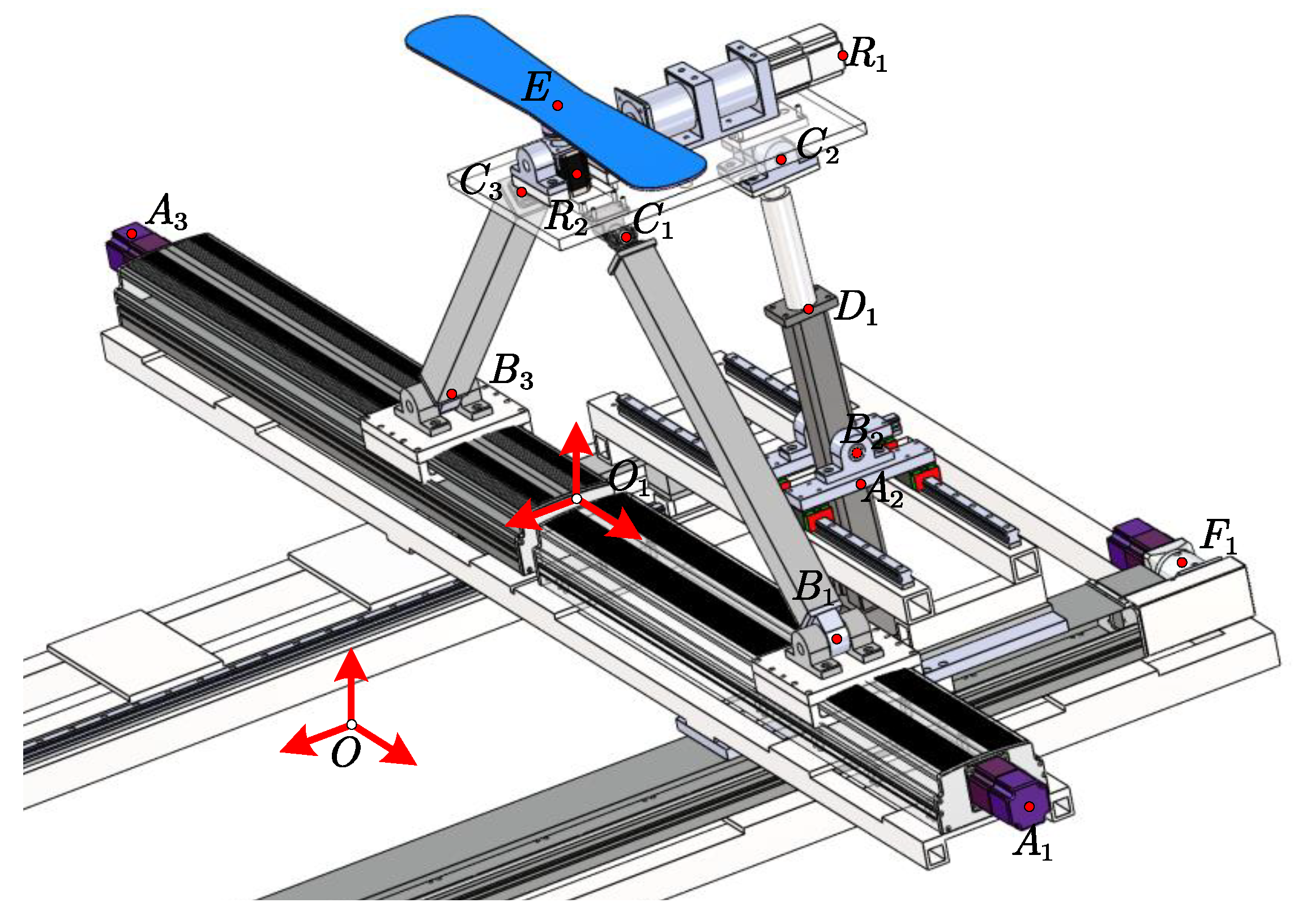
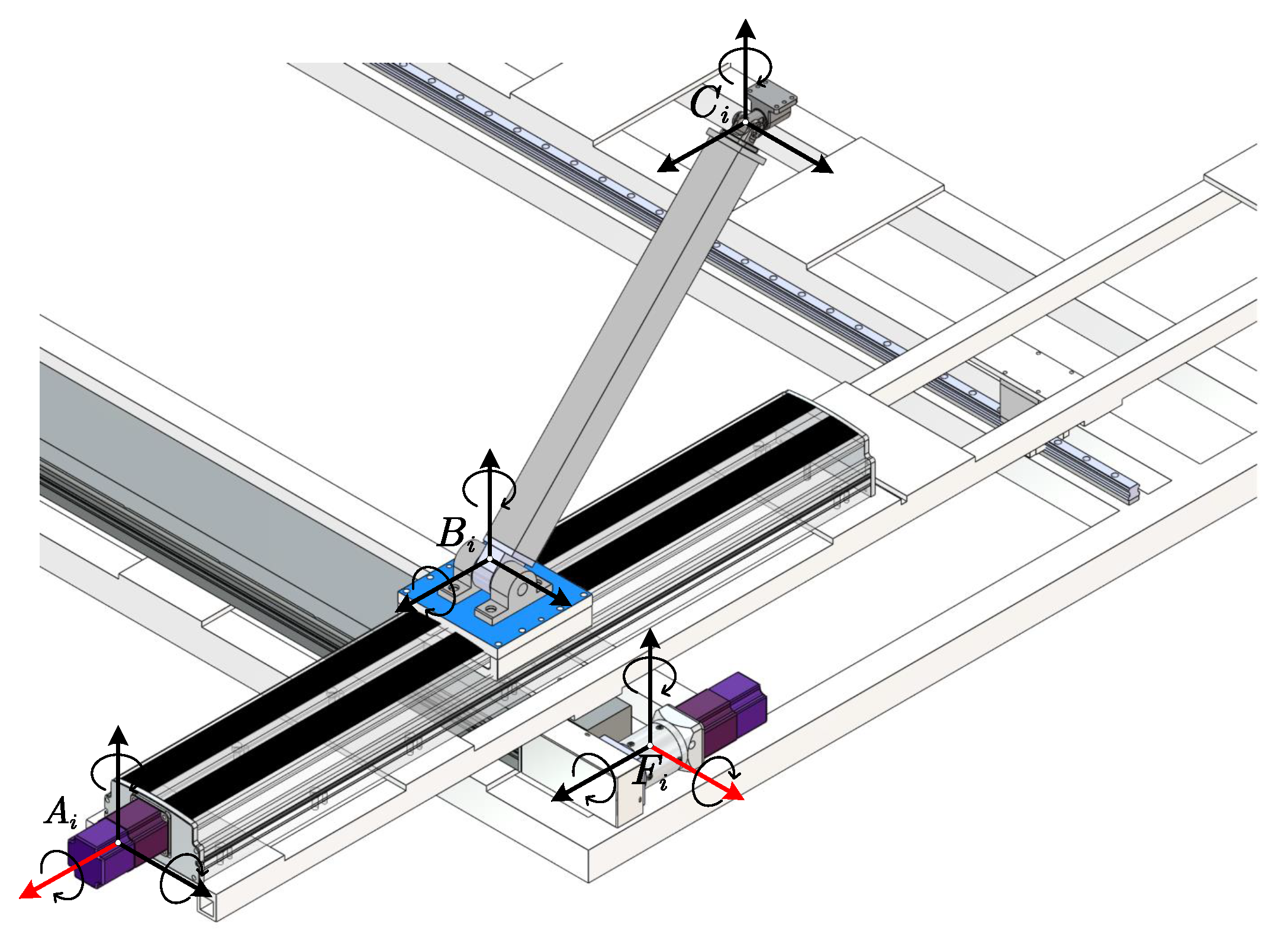
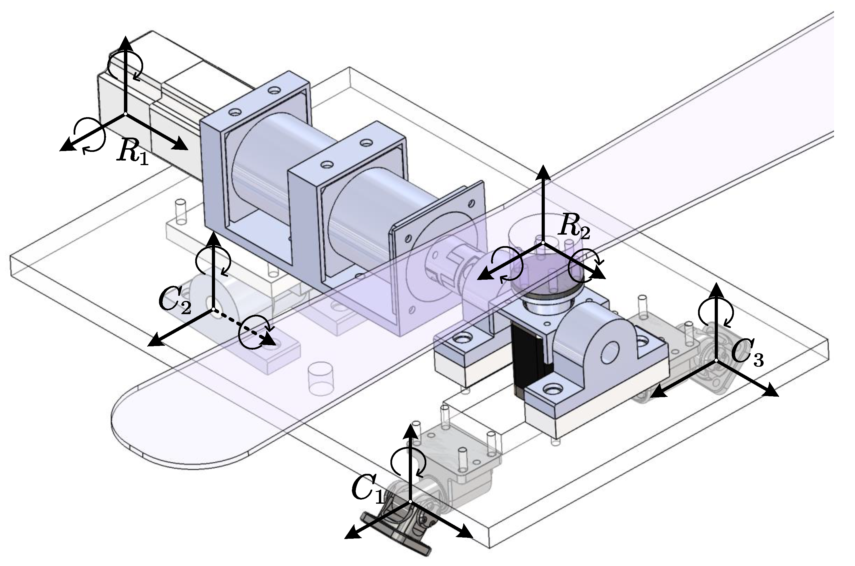
2.1. Mechanism Description

The assembly diagram of the 2(P-(2PRU–PRPR)-2R) mechanism is shown in Figure 1.
As evident from the Figure 1, the mechanism comprises two mirror-symmetrically arranged hybrid parallel modules to achieve high-fidelity dynamic simulation of skiing postures.Taking a unilateral hybrid mechanism for description, The stationary base assembly incorporates a tendon-driven pulley system (P). The intermediate layer integrates two axially aligned PRU-PRPR hybrid Subchains, comprising Worm-gear linear drives (P), Revolute joints (R), passive universal joints (U), and Electric cylinder (P) with fixed linkages. The end-effector level features two direct-drive rotary motors (2R) kinematically coupled to the skiing simulation platform.The PRU and PRPR kinematic Subchains are anchored to the stationary platform through prismatic joints (P). The PRU chain interfaces with a universal joint (U) via a rigid linkage, extending to the parallel module’s moving platform, whereas the PRPR chain integrates a linear actuator (P) connecting to a revolute joint (R) positioned beneath the moving platform. The parallel module’s upper stage houses a horizontally oriented pitch-axis motor with 500:1 reduction and a longitudinally aligned steering motor.
The driving pairs of the mechanism consist of: (i) the pulley (P) on the fixed platform, (ii) the worm gear (P) in the PRU chain, (iii) the electric cylinder (P) in the PRPR chain, (iv) the rotary motor (R) with a reducer, (v) the rotary motor (R) without a reducer.
The analytical framework initiates with the establishment of a coordinate system anchored at the kinematic center of unilateral mechanism’s (Figure 2), subsequently employing G F Set Theory to characterize the system’s degree of freedom. The red arrow represents the coordinate system and the mechanism coordinate system.
For the 2PRU–PRPR hybrid parallel subsystem, the G F set can be formulated as:
G F 1 ( T a T b 0 ; R α 00 )
Equation (1) establishes the parallel kinematic subsystem exhibits two translational and one rotational degrees of freedom (2T1R).
G F i set for the serial kinematic subsystem is formulated as:
G F 2 ( T a 0 00 ; 000 ) G F 3 ( 000 ; R α 4 R β 4 0 )
In summary, the G F set of the unilateral hybrid parallel-serial mechanism is mathematically defined as:
G F 1 G F 2 G F 3 = G F ( T a T b T c ; R α R β R γ )
The unilateral mechanism demonstrates 6-DOF mobility under G F Set Theory constraints (Equation (3)), whose symmetry-driven replication constructs a redundantly actuated 12-DOF hybrid parallel-serial topology. This hyper-redundant architecture achieves asynchronous bipedal gait emulation of ski-board dynamics through independently actuated kinematic chains governing left/right end-effector trajectories.

2.2. Inverse Kinematics for Hybrid Mechanisms

With reference to the global coordinate system shown in Figure 2, the actuated joint variables are parameterized as:
q = [ L 1 , L 2 , L 3 , α , β , γ ] T
with the following geometric constraints:
O 1 A 2 = a 2 A i B i = a i b i i = 1 , 2 , 3 O P C 1 = O P C 3 = b 1 = b 3 O P C 2 = c 2 B j C j = b j c j j = 1 , 3
where all rotations follow the right-hand rule convention.
The homogeneous transformation matrix for the serial–chain moving platform is derived using Denavit–Hartenberg (D–H) parameters listed in Table 1:
R P E = R 1 E R P 1 = c θ 1 c θ 2 s θ 1 c θ 1 s θ 2 d L R s θ 1 s θ 1 c θ 2 c θ 1 s θ 1 s θ 2 d L R c θ 1 s θ 2 0 c θ 2 0 0 0 0 1
where d L R denotes the translational displacement along the z-axis for revolute joints.
The parallel kinematic module, which provides two translational and one rotational (2T1R) degrees of freedom, has its homogeneous transformation matrix formulated as:
R P O 1 = 1 0 0 d x 0 c α s α 0 0 s α c α d z 0 0 0 1
where d x and d z denote translational displacements along the x- and z-axes, c = c o s · , s = s i n · , and α represents the rotation angle about the x-axis of the parallel module, respectively.
The tendon-driven pulley assembly mounted on the stationary platform exclusively provides y-axis translational motion. Its homogeneous transformation matrix is directly derived as:
R O 1 O = 1 0 0 0 0 1 0 L y + L 0 0 0 1 0 0 0 0 1
where L y denotes the translational displacement along the y-axis and L 0 represents the initial distance | | O O 1 | | under the reference configuration. The inverse kinematic solution for the mechanism’s pose is formulated as follows:
L 1 = x E + hc α s β + c 1 + b 1 c 1 2 z E h c α c β h 01 a 1 b 1 2 L 2 = a 2 d 2 c α 2 + z E h c α c β h 01 a 2 b 2 + d 2 s α 2 L 3 = x E hc α s β + c 3 + b 3 c 3 2 z E h c α c β h 01 a 3 b 3 2 L 4 = y E + h s α y O 1 θ y = β θ z = γ

2.3. Kinematic Analysis of Ski Simulation Platform

The mechanism is decomposed into three Kinematically Independent Subsystems via homogeneous transformation matrices, enabling simplified parametric analysis of hybrid parallel-serial systems through systematic decoupling of their kinematic interactions.

2.3.1. Kinematic Analysis of PRU Chains

The PRU Chains, as shown in Figure 3, is analyzed using closed-loop vector methodology to derive its kinematic Equation (10).
O O 1 l O O 1 + R O 1 O L A i l A i + L A i B i l A i B i + L B i C i l B i C i = R P O p i + r p i c i
where l O O 1 l A i l A i B i , i = 1 , 3 .
By selecting the intermediate vector O B i , Equation (10) can be decomposed into:
O O i l O O i + R O 1 O L A i l A i + L A i B i l A i B i = O B i O B i + R O 1 O L B i C i l B i C i = R P O O P i + P i C i
Temporal differentiation of Equation (11):
v o o 1 + R O 1 O L ˙ A i l A i + w B i × l A i B i L A i B i = v B i v B i + w B i × l B i C i L B i C i = R P O v P i + w P i × P i C i
The derivative L ˙ A i is analytically isolated by taking the dot product of both sides of Equation (12) with the unit vector l A i :
L ˙ A i = R O O 1 v B i l A i v A i = v B i
Let l B i C i be defined as the unit vector of the projection of B i C i onto the fixed platform, and let ε denote the angle between l B i C i and l B i C i .
The angular velocity component w B i is analytically isolated by taking the dot product of both sides of Equation (13) with the unit vector l B i C i :
w B i = R P O v P i + w P i × P C i v B i × l B i C i L B i C i cos ε
The position vector of the centroid for the rigid link B i C i is defined as B i C i = L B i C i l B i C i 2 , enabling subsequent derivation of the centroidal velocity and angular velocity through kinematic analysis:
v B i C i = v B i + w B i × L B i C i l B i C i 2 w B i C i = w B i
Through temporal differentiation of Equation (15), the linear and angular accelerations of individual components within the PRU kinematic chain are analytically derived:
a A i = a B i = v ˙ A i = v ˙ B i w ˙ B i = R P O v ˙ P i + w ˙ P i × P i C i v ˙ B i × l B i C i L B i C i sin ε v ˙ B i C i = v ˙ B i + L B i C i w ˙ B i × l B i C i L B i C i w B i 2 l B i C i 2 w ˙ B i C i = w ˙ B i

2.3.2. Kinematic Analysis of PRPR Subchains

The PRPR kinematic chain, illustrated in Figure 4, shares a closed-loop vector formulation analogous to Equation (12). The velocity and acceleration formulations of the A 2 B 2 subchain are identical to those defined in Equations (13)–(16). For the B 2 C 2 subchain, which incorporates a linear actuator (electric cylinder), kinematic analysis necessitates its decomposition into upper and lower linkage assemblies to derive centroidal velocities through rigid-body dynamics.
The position vector from revolute joint B 2 to the centroid of the lower linkage assembly in the prismatic joint is defined as: B 2 P B D = L B D l B D 2 . B 2 to the centroid of the upper linkage assembly in the prismatic joint is defined as: B 2 C 2 = L B C L D C 2 l B C , Therefore, the kinematic state at the centroid is characterized by the following derived quantities:
v P B G = v B 2 + w B 2 × L B G l B D 2 v P G D = v B 2 + w B 2 × L B D L G D 2 l B D w P B G = w P G D = w B 2
v ˙ P B G = v ˙ B 2 + L B G w ˙ B i × l B D 2 L B G w B i 2 l B D 2 v ˙ P G D = v ˙ B 2 + L B D L G D 2 w ˙ B i × l B D L B D L G D 2 w B i 2 l B D w ˙ P B G = w ˙ P G D = w ˙ B i

2.3.3. Kinematic Analysis of Serial Subchains

The serial chain of the platform comprises one pulley(P) joint and two revolute (R) joints, directly actuated by drive motors. The kinematic state of this 3-DOF system is characterized by the following velocity and acceleration profiles:
v F i = v R i w P i = w R i a F i = v ˙ R i w ˙ P i = w ˙ R i

3. Dynamic Modeling and Analysis of Hybrid Mechanisms

The dynamic model is established using the Newton-Euler formulation, incorporating the following simplifying assumptions: (i) Instantaneous effect of actuated joint forces/moments; (ii) External loads on the moving platform are reducible to a force-moment pair acting through its geometric center; (iii) All components are homogeneous rigid bodies with coincident geometric centers and centers of mass, the latter exhibiting a fixed offset along the negative Z-axis; (iv) Kinematic parameters (mass-center coordinates, velocities, accelerations, angular velocities, and angular accelerations) are transformed into the base coordinate system via homogeneous transformation matrices.

3.1. Dynamic Force/Torque Analysis of Kinematic Components

Based on the structural decomposition illustrated in Figure 2, the unilateral mechanism can be systematically divided into three functional subsystems for modular force analysis:
(1) PRU-Pulley Subsystem: Integrating a PRU (Prismatic-Revolute-Universal) kinematic chain with a tendon-driven pulley transmission system;
(2) PRPR Hybrid Subsystem: Composed of a PRPR (Prismatic-Revolute-Prismatic-Revolute) closed-loop configuration;
(3) End-effector Subsystem: Functioning as the terminal motion interface;
(4) This model assumes linear material behavior and does not account for thermal gradients, hysteresis, or actuator dynamics.

3.1.1. Force/Torque Analysis of PRU-Pulley Subsystem

Force analysis is performed on the kinematic chains of the PRU-Pulley Subsystem as illustrated in Figure 5, where: Red vectors denote actuation forces; Black vectors represent constraint forces; Curved black vectors indicate constraint moments.
As demonstrated in Figure 5, the force and moment equilibrium equations of the mechanism’s dynamics can be expressed as:
F j i m j g + F k 1 = F j i · r j i + M j i + M k 1
where, j = A , B , C , F denotes reference points of kinematic subsystem, i = 1 , 3 , 4 , 6 denotes component identifiers within subsystem, F j i and M j i denotes constraint force/Torque on subsystem, F k 1 = m j v ˙ j i and M k 1 = I T J j + m j d j 2 I w ˙ j denotes inertial force/Torque on subsystem, m j denotes the mass at centroid of each chain, r j i Position vector of chain’s centroid., The black arrow represents constraint force, and the red arrow represents driving force, The following representations are the same.
Simplification of Equation (20):
I r j i 0 0 I F j i M j i = G 1
where
G 1 = m j P 1 0 0 P 1 H T J j + d j 2 v ˙ j i w ˙ j i
P 1 = g / v ˙ j i w ˙ j i

3.1.2. Force/Torque Analysis of PRPR Hybrid Subsystem

Force analysis is performed on the kinematic chains of the PRPR Hybrid Subsystem as illustrated in Figure 6.
The force and moment equilibrium equations of the mechanism’s dynamics can be expressed as:
F L i m L + F k 2 = F L i · r L i + M L i + M k 2
where L = A , B , C , D denotes reference points of kinematic subsystem, i = 2 , 5 denotes component identifiers within subsystem, F L i and M L i denotes constraint force/Torque on subsystem, F k 2 = m L v ˙ L i and M k 2 = I T J L + m L d L 2 I w ˙ L denotes inertial force/Torque on subsystem, m L denotes the mass at centroid of each chain; r L i Position vector of chain’s centroid.
Simplification of Equation (22):
I r L i 0 0 I F L i M L i = G 2
where
G 2 = m L P 2 0 0 P 2 H T J L + d L 2 v ˙ L i w ˙ L i
P 2 = g / v ˙ L i w ˙ L i

3.1.3. Force/Torque Analysis of End-Effector Subsystem

Force analysis is performed on the kinematic chains of the PRPR Hybrid Subsystem as illustrated in Figure 7.
The force and moment equilibrium equations of the mechanism’s dynamics can be expressed as:
F M i m M + F k 3 = F M i · r M i + M M i + M k 3
where M = C , R denotes reference points of kinematic subsystem, i = 1 , 2 , 3 denotes component identifiers within subsystem, F M i and M M i denotes constraint force/Torque on subsystem, F k 3 = m M v ˙ M i and M k 3 = I T J M i + m M i d M i 2 I w ˙ M i denotes inertial force/Torque on subsystem, m M denotes the mass at centroid of each chain; r L i Position vector of chain’s centroid.
Simplification of Equation (24):
I r M i 0 0 I F M i M M i = G 3
where
G 3 = m M P 3 0 0 P 3 H T J M + d M 2 v ˙ M i w ˙ M i
P 2 = g / v ˙ M i w ˙ M i
The complete dynamic model is synthesized through Equations (21), (23) and (25):
U v w Γ n = Θ q
where
U v w =
m j · P 1 0 0 P 1 H T J j + d j 2 I r j i 0 0 I m L · P 2 0 0 P 2 H T J L + d L 2 I r L i 0 0 I m M · P 3 0 0 P 3 H T J M + d M 2 I r M i 0 0 I
Γ n = v ˙ j i , w ˙ j i , v ˙ L i , w ˙ L i , v ˙ M i , w ˙ M i T
Θ q = F j i , M j i , F L i , M L i , F M i , M M i T

3.2. Dynamic Model Validation Through Numerical Simulation

To validate the accuracy of the developed dynamic model, the 3D assembly was imported into Adams simulation software for verification. Mechanism parameters, as specified in Table 2, include structural components assigned steel material properties, with the moving platform and joints modeled as rigid bodies. The end-effector trajectory was subsequently imported into both Adams and MATLAB environments for co-simulation—performing multibody dynamics simulation and numerical computation, respectively. Comparative analysis was conducted by benchmarking the simulation outcomes against numerical computations to verify the fidelity of the dynamic modeling methodology.
x = 175 s i n π / 100 t i m e y = 320 + 200 s i n π / 100 t i m e z = 70 s i n π / 60 t i m e θ 1 = 44 d + 60 d s i n π / 100 t i m e θ 2 = 3 d + 10 d s i n π / 100 t i m e
The variations in Z-axis force and moment are analyzed in Figure 8. The consistent trends between the simulated curves and actual motion trajectories are demonstrated in Figure 8a,b. Furthermore, Figure 8c reveals that the maximum relative error of real-time force variation throughout the operational cycle remains within 0.53%, demonstrating high temporal fidelity of the dynamic model, Validating the dynamic model’s fidelity to physical behavior. However, as is shown in Figure 8d, significant moment deviations are observed between 120 and 170s under the predefined trajectory, with a peak relative error of 9.61%. This phenomenon indicates a progressive degradation in computational accuracy of the dynamic model during high-speed reciprocating motion, whereas precision remains acceptable only under low-speed quasi-static conditions. Such pronounced computational discrepancies impose non-negligible on the control system, notably increasing real-time compensation efforts and potentially compromising trajectory tracking stability.
To enhance dynamic modeling fidelity under practical operational constraints, this study proposes an optimization methodology that establishes deformation superposition compatibility equations based on the inherent material properties of structural members. This approach rigorously analyzes geometric relationships between component deformations and end-effector pose variations, enabling precision compensation for elastokinematic effects in parallel-serial hybrid mechanisms.

4. Mechanism Deformation Compatibility Analysis

Under operational loading conditions combining external forces, gravitational effects, and inertial loads, the structural linkages in the mechanism demonstrate coupled elastostatic deformations, where compressive straining predominantly occurs in the connecting members. This elastostatic behavior is particularly pronounced in the 2PRU–PRPR kinematic subsystem, where three parallel branches impose only two degrees of freedom constraints on the moving platform, resulting in redundant moments. This dual deformation mechanism arises from the superposition of intrinsic compressive deformation (stemming from axial loading) and extrinsic bending deformation (caused by transverse moment excitation), revealing critical stress concentration patterns in over-constrained parallel modules.
The integration of material mechanics theory is essential to decouple axial and shear deformation mechanisms in structural members. this research establish independent deformation compatibility equations that satisfy both geometric continuity and static equilibrium conditions. The dual-path modeling strategy fundamentally avoids linear correlation with prior rigid-body dynamic models.
Let the deformation-induced positioning error of the end-effector platform be defined as:
Δ p = Δ x , Δ y , Δ z T
The rotational transformation matrix perturbed by kinematic errors can be expressed as:
δ P O 1 R = 1 δ z δ y δ z 1 δ x δ y δ x 1

Deformation Compatibility Formulation for Kinematic Chain

Taking the upper link of the Electric cylinder in the PRPR Subsystem as an example, the vector equation prior to compressive deformation of the subchain can be formulated as:
O D + L D C 1 · l D C 1 = p + P O R · P C 1
Following deformation, the vector equation can be revised and expressed as:
O D + L D C 1 · l D C 1 + δ l D C 1 + Δ p i = p + Δ t + δ P O R · P O R · P C 1
Subtract (30) from (31)
Δ L D C 1 · δ l D C 1 = Δ p i + Δ t + δ P O R I D C 1 · P O R · P C 1
Dot multiplying both sides of Equation (32) by l D C 1 yields:
Δ L D C = Δ p i + Δ t + δ P O R I D C 1 · P O R · P C 1 · l D C 1
where Δ L D C 1 and Δ t denote axial compression and bending deformations, respectively.
Figure 9 shows the deformation and force distribution schematic of the subchain.
p 2 i = m C 1 D · 0 , 0 , g T / L C 1 D , q 2 i = m C 1 D · v ˙ C 1 D / L C 1 D denote the uniformly distributed gravitational and inertial forces along the rod, respectively.
The axial force at position x from C 2 is obtained:
Δ L C D = 0 L C 2 D F d E · V 2 d x
where V 1 , E denote the rod’s cross-sectional area and elastic modulus, respectively.
F d = F C 2 x F C 2 y F C 2 z m C 2 D · v ˙ C 2 D . L C 2 D x L C 2 D + p 2 i . L C 2 D x L C 2 D · l C 2 D
Substituting Equation (35) into Equation (34) yields the rod’s axial deformation:
Δ L C D = 0 L C 2 D F d E · V 2 d x
The deflection vector can be analogously formulated through equivalent derivation:
Δ t = f b · l b
where
f b = M C 1 y · sin θ C 1 D · L C 1 D 2 E I
l b = R P O 1 · 0 1 0 0 × l C 1 D
By combining Equations (32), (34) and (37) to compute Δ p , we construct deformation compatibility equations that form a coupled iterative system; Solving this system yields optimized forces/moments (Figure 10), with final dynamical parameters determined via nonlinear least-squares minimization.
Optimized force-moment evolution profiles are derived through deformation compatibility equations with Table 2 parameters.
As shown in Figure 11, the implementation of the deformation compatibility equation achieves a 0.98% deviation in moment calculations(see Figure 11a,c). This result demonstrates simultaneous improvements in both moment accuracy (optimization error ≤ 1%) and force computation precision, with a maximum relative error of 0.12% (see Figure 11a,c). The numerical integrity of the proposed model is thereby confirmed.

5. Conclusions

This study establishes a precision dynamics framework for hybrid 2(P-(2PRU–PRPR)-2R mechanisms through:
(1) Unified Dynamics Formulation:
A novel synthesis methodology integrating Newton-Euler formulations, D-H parameters, and closed-loop vector techniques resolves the challenge of precise dynamic modeling for hybrid parallel mechanisms.
(2) Deformation-Compensated Validation:
Rigorous computational verification reveals: Initial rigid-body model limitations (5.2% moment deviations) Deformation compatibility equations enable:
82.3% moment accuracy improvement (final deviation ≤ 0.98%)
Force precision enhancement to 0.12% relative error Cross-platform consistency (MATLAB/Adams RMS error < 0.15%)

Author Contributions

Q.G. conducted theoretical research and wrote the original draft; H.T. conceptualized the study and prepared Figure 1, Figure 2, Figure 3, Figure 4, Figure 5 and Figure 6; Z.W. provided research facilities and secured Co-Simulation funding; Y.L. supervised the theoretical framework and secured funding for model development; B.L. and W.L. prepared Figure 7, Figure 8, Figure 9 and Figure 10. All authors have read and agreed to the published version of the manuscript.

Funding

This work was supported by Research Innovation Fund for Chinese Universities, Grant No. [2023DT022], Center of Scientific Research and Development in Higher Education Institutes Foundation, Grant No. [2023DT020]: <Research on Intelligent palletizing robot for laser cutting steel plate> and Major Science and Technology Achievement Transformation Program of Hebei Province, Grant No. [23280101Z].

Data Availability Statement

Raw simulation data storage solutions are being developed and will be accessible via institutional repository after 2025.

Conflicts of Interest

The authors declare no conflicts of interest.

References

  1. Wang, L.; Guo, F.; Lu, W.; Li, Y.; Zhang, L. Non-inertial System Dynamic Modeling of 3UPS/S Ship Stability Platform. J. Mech. Eng. 2020, 56, 20–29. [Google Scholar]
  2. Cai, A.-Y.; Yao, X.-L. Trajectory optimization with constraints for alpine skiers based on multi-phase nonlinear optimal control. Front. Inf. Technol. Electron. Eng. 2020, 21, 1521–1535. [Google Scholar] [CrossRef]
  3. SONG, C.j.; Xiao-dan, C.; Si-wen, S. Design and Implementation of Visual System of Simulated Ski Machine Based on Unity3D. Ind. Appl. Commun. 2021, 40, 158–161. [Google Scholar]
  4. Yu, Z.; Liu, Y.; Liu, Y.; Wan, Y.; Yang, W.; Daoai, W.; Feng, Z. Wearable Snow Friction Harvester Based on Traditional Skis. Tribology 2024, 44, 97–106. [Google Scholar] [CrossRef]
  5. Guan, L.; Cong, X.; Zhang, Q.; Zhou, X. Design of visualization system for indoor skiing teaching and training based on micro-inertia and Unity3D. Exp. Technol. Manag. 2021, 38, 152–156. [Google Scholar] [CrossRef]
  6. Gao, H.; Qiao, R.; Liu, J. Design of Ski Training Equipment Based on Industrial Robot Technology. Mech. Eng. 2024, 135–140. [Google Scholar]
  7. Cheng, Y.; Ren, G.; Dai, S. The multi-body system modelling of the Gough-Stewart platform for vibration control. J. Sound Vib. 2004, 271, 599–614. [Google Scholar] [CrossRef]
  8. Engin, M. Controller Design for Parallel Mechanism Solar Tracker. Machines 2023, 11, 372. [Google Scholar] [CrossRef]
  9. Olar, M.L.; Panaite, A.F.; Leba, M.; Sibisanu, R. Stewart Platform Modified into a Bio-inspirational Device of the Human Shoulder. In Trends and Applications in Information Systems and Technologies, VOL 4, Proceedings of the 9th World Conference on Information Systems and Technologies (WorldCIST), Electr Network, 30 March–2 April 2021; Advances in Intelligent Systems and Computing; Rocha, A., Adeli, H., Dzemyda, G., Moreira, F., Correia, A., Eds.; Springer: Berlin/Heidelberg, Germany, 2021; Volume 1368, pp. 151–160. [Google Scholar] [CrossRef]
  10. Zhao, L.; Huang, J. Design of virtual interactive educational games based on human perception. Entertain. Comput. 2025, 52, 100891. [Google Scholar] [CrossRef]
  11. Liu, C.; He, Q.; Tang, Q.; Ren, K.; Gong, J.; Zhang, D. Novel control strategy for the energy recovery system of a hydraulic excavator. Int. J. Agric. Biol. Eng. 2024, 17, 94–101. [Google Scholar] [CrossRef]
  12. Liu, B.; Gan, J.; Xu, J.; Ellis, D.; Zou, R.; Yu, A.; Zhou, Z. Numerical simulation of operations of hydraulic excavators for polydisperse bulk materials and different configurated buckets. Autom. Constr. 2024, 157, 105154. [Google Scholar] [CrossRef]
  13. Jaiswal, S.; Jiang, D.; Xiang, S.; Nikitina, A.; Khadim, Q.; Mikkola, A. Gamification of control valves in real-time multibody simulation of an excavator. Multibody Syst. Dyn. 2024. [Google Scholar] [CrossRef]
  14. Song, H.; Li, G.; Li, Z.; Xiong, X. Trajectory Control Strategy and System Modeling of Load-Sensitive Hydraulic Excavator. Machines 2023, 11, 10. [Google Scholar] [CrossRef]
  15. Ding, J.; Ding, H.; Yang, W. Dynamic Modeling of a Novel Multi-Loop Multi-Body Mechanism of Face-Shovel Excavator. Chin. J. Mech. Eng. 2025, 38, 38. [Google Scholar] [CrossRef]
  16. Hu, B.; Zhang, L.; Yu, J. Kinematics and dynamics analysis of a novel serial-parallel dynamic simulator. J. Mech. Sci. Technol. 2016, 30, 5183–5195. [Google Scholar] [CrossRef]
  17. Li, Y.; Guo, Y.; Zhang, Y.; Zhang, L. Dynamic Modeling Method of Spatial Passive Over-constrained Parallel Mechanism Based on Newton Euler Method. J. Mech. Eng. 2020, 56, 48–57. [Google Scholar]
  18. Huang, H.; Han, H.; Li, D.; Xu, Z.; Wu, Q. Inverse dynamics analysis of a 6-RR-RP-RR parallel manipulator with offset universal joints. Robotica 2024, 42, 1549–1567. [Google Scholar] [CrossRef]
  19. Zhao, J.S.; Wei, S.T.; Sun, X.C. Dynamics of a 3-UPS-UPU-S Parallel Mechanism. Appl. Sci. 2023, 13, 3912. [Google Scholar] [CrossRef]
  20. Boyer, F.; Gotelli, A.; Tempel, P.; Lebastard, V.; Renda, F.; Briot, S. Implicit Time-Integration Simulation of Robots With Rigid Bodies and Cosserat Rods Based on a Newton-Euler Recursive Algorithm. IEEE Trans. Robot. 2024, 40, 677–696. [Google Scholar] [CrossRef]
  21. Chen, Z.; Song, J.; Li, N.; Yan, W.; Zhao, C. Design and dynamics modeling of a novel 2R1T 3-DOF parallel motion simulator. J. Braz. Soc. Mech. Sci. Eng. 2023, 45, 234. [Google Scholar] [CrossRef]
  22. Liu, Z.; Wang, G.; Rui, X.; Wu, G.; Tang, J.; Gu, L. Modeling and simulation framework for missile launch dynamics in a rigid-flexible multibody system with slider-guide clearance. Nonlinear Dyn. 2024, 112, 21701–21728. [Google Scholar] [CrossRef]
  23. Liu, K.; Song, T.; Xu, X.; Wang, H.; Meng, Q. Dynamics modeling and typical motion performance analysis for a multi-joint autonomous underwater vehicle. Ocean. Eng. 2023, 281, 114999. [Google Scholar] [CrossRef]
  24. Liu, T. Analysis of human lower limb dynamics and gait reconstruction. J. Mech. Med. Biol. 2024, 24, 2440027. [Google Scholar] [CrossRef]
  25. Urbas, A.; Augustynek, K.; Martsenyuk, V. The Influence of the Load Modelling Methods on Dynamics of a Mobile Crane. In Perspectives in Dynamical Systems I-Applications, DSTA 2021, Proceedings of the 16th International Conference on Dynamical Systems—Theory and Applications (DSTA), Electr Network, 6–9 December 2021; Springer Proceedings in Mathematics and Statistics; Awrejcewicz, J., Ed.; Lodz Univ Technol, Dept Automat, Biomechan & Mechatron: Łódź, Poland; Polish Minister Educ & Sci: Warsaw, Poland, 2024; Volume 453, pp. 559–569. [Google Scholar] [CrossRef]
  26. Chen, R.; Gu, Y.; Qiu, G.; Huang, P. Dynamic analysis of planetary gear transmission based on Lagrange interpolation polynomials. Meas. Sci. Technol. 2024, 35, 11. [Google Scholar] [CrossRef]
  27. Yang, H.; Ni, T.; Wang, Z.; Wang, Z.; Zhao, D. Dynamic modeling and analysis of traction operation process for the shipboard helicopter. Aerosp. Sci. Technol. 2023, 142, 108661. [Google Scholar] [CrossRef]
  28. Qiu, J.; Qiu, W.; Niu, A.; Han, G.; Wang, S.; Sun, Y. Modeling and Analysis of Offshore Gangway under Dynamic Load. J. Mar. Sci. Eng. 2023, 11, 77. [Google Scholar] [CrossRef]
  29. Luo, Z.; Xiao, J.; Liu, S.; Wang, M.; Zhao, W.; Liu, H. A dynamic parameter identification method for the 5-DOF hybrid robot based on sensitivity analysis. Ind. Robot.- Int. J. Robot. Res. Appl. 2024, 51, 340–357. [Google Scholar] [CrossRef]
  30. Zhu, R.; Yang, G.; Fang, Z.; Chen, C.Y.; Li, H.; Zhang, C. Quasi-Coordinates-Based Closed-Form Dynamic Modeling and Analysis for a 2R1T PKM with a Rigid-Flexible Structure. Machines 2023, 11, 260. [Google Scholar] [CrossRef]
  31. Wu, N.; Yang, H.; Afsar, H.; Wang, B.; Fan, J. Analysis of Train-Track-Bridge Coupling Vibration Characteristics for Heavy-Haul Railway Based on Virtual Work Principle. Sensors 2023, 23, 8550. [Google Scholar] [CrossRef]
  32. Di Gregorio, R. Dynamic model of single-DOF spherical mechanisms based on instantaneous pole axes and Eksergian’s equation. Mech. Mach. Theory 2024, 200, 105720. [Google Scholar] [CrossRef]
  33. ISO 14839-1:2018; Mechanical Vibration—Vibration of Rotating Machinery Equipped with Active Magnetic Bearings—Part 3: Evaluation of Stability Margin. ISO: Geneva, Switzerland, 2006.
  34. Gupta, A.; Lee, C. Real-time control benchmarks for multi-axis motion platforms. Mechatronics 2020, 65, 102301. [Google Scholar]
  35. Feng, G.; Jia, S.; Chen, J.; Zhou, X. Newton-Eulerian Dynamics of a Walkable Lander. Spacecr. Recovery Remote Sens. 2024, 45, 53–64. [Google Scholar]
  36. Liu, Y.; Cao, X.; Wang, X.; Wang, F.; Xu, Z.; Lu, H. Forward kinematics of the 6-DOF parallel mechanism based on homogeneous transformation matrix numerical solution. J. Harbin Eng. Univ. 2013, 34, 894–898. [Google Scholar]
  37. Zhang, J.; Xie, F.; Liu, X.J. Dynamic modeling of hybrid robots through stiffness directionally releasing and multiple-node dynamics assembling. Mech. Mach. Theory 2025, 209, 106002. [Google Scholar] [CrossRef]
  38. Yang, J.; Harsono, E.; Yu, H. Dynamic modeling and validation of a hybrid-driven continuum robot with antagonistic mechanisms. Mech. Mach. Theory 2024, 197, 105635. [Google Scholar] [CrossRef]
  39. Shen, N.; Yuan, H.; Li, J.; Wang, Z.; Lu, N.; Lu, Y. Dynamic Modeling and Simulation of a Hybrid Robot. J. Mech. Robot.-Trans. Asme 2023, 15, 011012. [Google Scholar] [CrossRef]
  40. Gao, F.; Yang, J.; Ge, Q. GF Set Theory for Type Synthesis of Parallel Mechanisms; China Machine Press: Beijing, China, 2011. (In Chinese) [Google Scholar]
  41. Cammarata, A.; Maddio, P.D.; Sinatra, R.; Tian, Y.; Zhao, Y.; Xi, F. Elastostatic analysis of a module-based shape morphing snake-like robot. Mech. Mach. Theory 2024, 194, 105580. [Google Scholar] [CrossRef]
Figure 1. Assembly of the 2(P-(2PRU–PRPR)-2R) Mechanism.
Dynamics 05 00030 g001
Figure 2. Schematic of the Kinematic Coordinate System for the Unilateral Ski Simulation Platform.
Dynamics 05 00030 g002
Figure 3. Schematic of PRU Chains.
Dynamics 05 00030 g003
Figure 4. Schematic of PRPR Subchains.
Dynamics 05 00030 g004
Figure 5. Schematic of PRU-Pulley Subsystem.
Dynamics 05 00030 g005
Figure 6. Schematic of PRU-Pulley Subsystem.
Dynamics 05 00030 g006
Figure 7. Schematic of PRU-Pulley Subsystem.
Dynamics 05 00030 g007
Figure 8. Comparative Simulation of Z-axis Force/Torque in the Mechanism. (a,b) show the force/torque variation curves, while (c,d) show the variation of force/torque calculation errors.
Dynamics 05 00030 g008
Figure 9. Subchain Deformation-Force Interaction Schematic.
Dynamics 05 00030 g009
Figure 10. Iterative Optimization Framework for the Enhanced Newton-Euler Model.
Dynamics 05 00030 g010
Figure 11. (a,b) show the changes in force/torque curves before and after optimization, while (c,d) show the changes in force/torque errors before and after optimization.
Dynamics 05 00030 g011
Table 1. D–H parameters of the. serial–chain moving platform.
i α i 1 a i 1 d i 1 θ i 1
1 90 00 θ 1
2 90 0 d L R θ 2
Table 2. Key parameters of the simulated hybrid mechanism.
ParametersValues
Stroke of Pulley/m5
Stroke of Servo motor 1/rad π / 6 π / 6
Stroke of Servo motor 2/rad π / 2 π / 2
Length of fixing rod/m0.8
Stroke of electric cylinder/m 0 0.64
Length of servo motor/m0.12
Size of intermediate platform/m0.35
Disclaimer/Publisher’s Note: The statements, opinions and data contained in all publications are solely those of the individual author(s) and contributor(s) and not of MDPI and/or the editor(s). MDPI and/or the editor(s) disclaim responsibility for any injury to people or property resulting from any ideas, methods, instructions or products referred to in the content.

