Article

A New Approach for Solving Nonlinear Oscillations with an m-Degree Odd-Power Polynomial Restoring Force

by
Stylianos Vasileios Kontomaris
1,2,3,*,
Gamal M. Ismail
4,
Vassilis Alimisis
2,
Christos Dimas
5 and
Anna Malamou
5,*
1
School of Sciences, European University Cyprus, 2404 Nicosia, Cyprus
2
Department of Engineering and Construction, Metropolitan College, 15125 Athens, Greece
3
BioNanoTec Ltd., 2043 Nicosia, Cyprus
4
Department of Mathematics, Faculty of Science, Islamic University of Madinah, Madinah 42351, Saudi Arabia
5
School of Electrical and Computer Engineering, National Technical University of Athens, 9, Iroon Polytechniou St., 15780 Athens, Greece
*
Authors to whom correspondence should be addressed.
Dynamics 2025, 5(1), 9; https://doi.org/10.3390/dynamics5010009
Submission received: 14 January 2025 / Revised: 1 March 2025 / Accepted: 3 March 2025 / Published: 5 March 2025

Abstract

:
Solving nonlinear oscillations is challenging, as solutions to the corresponding differential equations do not exist in most cases. Therefore, numerical methods are usually employed to calculate the precise oscillation frequency. In addition, many interesting mathematical approaches leading to approximate solutions have also been developed. This paper focuses on a classic case of a nonlinear oscillator: the oscillator with an odd-power polynomial restoring force. This case encompasses nearly all scenarios of undamped nonlinear oscillations. The idea is to combine two well-known strategies from the literature: He’s approximation, which is simple to apply and valid for small amplitudes, and the analytical solutions for oscillations with power-law restoring forces. It is shown that by combining these approaches, a universal equation accurate for any amplitude is derived. Many tests of the proposed method’s accuracy are presented using polynomials of various degrees and classic examples, such as the rotating pendulum, cubic–quintic Duffing oscillators, and oscillators with cubic and harmonic restoring forces. In addition, a novel ‘electrical analogue’ of the oscillation with a polynomial-type restoring force is introduced to demonstrate that the methods presented in this paper can be applied in real industrial applications.

1. Introduction

Nonlinear oscillations are present in a wide range of scientific areas, including mechanics and engineering [1,2,3,4,5,6], physics [7,8,9,10,11], and mathematics [12,13,14,15]. These oscillations are typically modelled using nonlinear differential equations (NDEs). However, the complexity of NDEs due to their strong nonlinearity has led to considerable interest in developing precise approximation methods. In recent decades, a variety of techniques have been proposed to solve NDEs. Traditional perturbation methods have been inadequate for handling strongly nonlinear oscillators, as they fail to provide sufficiently accurate approximations. To overcome these shortcomings, various analytical methods have been explored. Several techniques have been employed, including the harmonic balance method [16,17], variational iteration method [18,19], homotopy analysis method [20,21], homotopy perturbation method [22,23], Li-He’s modified homotopy perturbation method [24], enhanced homotopy perturbation method [25], asymptotic method [26,27], energy balance method [28], differential transformation method [29], parameter expansion method [30,31], variational principle [32], frequency–amplitude formulation [33], and many others. Moreover, considerable efforts have been made to develop general equations that address a wide range of nonlinear oscillation cases. For example, several researchers have proposed approximate solutions for nonlinear oscillations with cubic and harmonic restoring forces [34,35]. This case holds significant importance, as it can describe a wide range of phenomena in mathematics, physics, and engineering [35,36]. It serves as a general model for many specific cases, including the Duffing equation [37], the simple pendulum [38], the cubic–quintic Duffing oscillator [39], and the capillary oscillator [40,41]. Therefore, deriving approximate solutions for general cases is of great significance in the field of nonlinear science. In this paper, the general case of oscillation with an odd-power polynomial restoring force is examined. Specifically, the following case is addressed:
d 2 x d t 2 + f x = 0
where
f x = i = 0 n c n x 2 n + 1 = c 0 x + c 1 x 3 + c 2 x 5 + c 3 x 7 + c 4 x 9 + c 5 x 11 + + c n x 2 n + 1
In Equation (2), c 0 , c 1 ,…, c n are constant coefficients. In this paper, only cases with coefficients with appropriate values to satisfy the condition x d 2 x d t 2 < 0 (for nonzero x) are considered, in order to ensure oscillatory motion.
It is important to note that an exact analytical solution does not exist for differential Equation (1) when f(x) is given by Equation (2). Therefore, the objective of this paper is to provide a simple approximation for the angular frequency in this general case. This approximation is particularly significant because it remains valid in nearly all cases of nonlinear undamped oscillations, as any odd function f(x) can be approximated by a polynomial of the form in Equation (2) using a Maclaurin series expansion. The cases mentioned above, the Duffing equation, the simple pendulum, the cubic–quintic Duffing oscillator, the capillary oscillator, etc., are all special cases of undamped oscillations that can be approximated using Equations (1) and (2) through a Maclaurin series expansion [36,37]. The number of terms in Equation (2) (i.e., the number of n-values) depends on the oscillation’s amplitude (i.e., the maximum x-value). A typical example to demonstrate this is the simple pendulum. For an amplitude of π/2, using three terms in Equation (2) (i.e., n = 2) through a Maclaurin series expansion provides excellent accuracy [37]. For larger amplitudes, a greater number of terms should be considered (n > 2).
It is important to note that there are many approximate equations in the literature focused on the quick calculation of the angular frequency of nonlinear undamped oscillations [11,14,33,36,39]. The simplest approach to solving equations with a polynomial-type restoring force was proposed by He [39]. The method is based on determining the angular frequency of the oscillation as follows:
ω H e ( 1 ) = d f x d x x = A 2 1 / 2
where A is the oscillation’s amplitude. Equation (3) is effective for the case of a Duffing oscillator, where f x = c 0 x + c 1 x 3 , [42]. Therefore,
ω H e ( 1 ) = c 0 + 3 4 c 1 A 2 1 / 2
For the cubic–quintic Duffing oscillator, where f x = c 0 x + c 1 x 3 + c 2 x 5 , a modification of Equation (3) has been proposed, as Equation (1) results in significant errors for large amplitudes (approximately 25%) [39]. Specifically,
ω H e ( 2 ) = 1 3 d f x d x x = 0.3 A + d f x d x x = 0.5 A + d f x d x x = 0.7 A 1 / 2
Equation (5), for the cubic–quintic Duffing oscillator is written as follows:
ω H e ( 2 ) = c 0 + 0.83 c 1 A 2 + 0.51783 c 2 A 4 1 / 2
The error associated with Equation (6) is small for large amplitudes (approximately 3.6%); however, for A = 1, the error is not negligible, being approximately 10% [39].
Furthermore, consider the case of power-law restoring forces ( F = c n | x | m ) [43,44]. He’s equations above fail to provide accurate approximations for this case. However, the differential equation of oscillation with power-law restoring forces can be analytically solved, as demonstrated in [44]. Considering the special case where the exponent of the restoring force is an odd number, the following can be concluded:
d 2 x d t 2 + c n x m = 0
where m = 1, 3, 5, … The analytical solution for the angular frequency of Equation (7) is provided below [43,44]:
ω p o w e r   l a w = c n π m + 1 2 Γ 3 + m 2 m + 1 Γ 1 m + 1 A m 1 2
In Equation (8), Γ represents the gamma function. The aim of this paper is to combine He’s equation with Equation (8) to derive a globally accurate formula for the angular frequency of oscillations with an m-degree odd-power polynomial restoring force, applicable to any amplitude. This paper is organized as follows: Section 2 introduces a new equation based on He’s approach and Equation (8). Section 3 demonstrates that the proposed equation is accurate for any amplitude, with an error of less than 1.6% in all cases. In Section 4, the approach is tested on a rotating pendulum (Section 4.1), showing excellent accuracy, while Section 4.2 applies it to an electrical analogue of oscillations with an odd-polynomial restoring force, highlighting its industrial relevance. Section 5 discusses the special case of oscillations with a 9th-degree polynomial restoring force. Finally, Section 6 provides additional remarks on the examples used in this paper and introduces further examples. In addition, the limitations of the proposed approach are highlighted.

2. Deriving a New Equation

This section presents the method for deriving a new approximate equation to solve nonlinear oscillations. The procedure is based on He’s approximation (Equation (3)) and Equation (8). As already mentioned, Equation (8) provides the angular frequency for Equation (1) when f x = c n x m (for m = 1, 3, 5, …). The first step is to write Equation (8) with respect to the function f x :
ω = m λ m c n A m 1 2
where
λ m = 1 + 1 m 2 π Γ 3 + m 2 ( m + 1 ) Γ 1 m + 1
Therefore,
ω 2 = m c n λ m 2 m 1 A m 1
In addition,
f x = c n x m d f x d x = m c n x m 1
By combining Equations (11) and (12), the angular frequency is calculated as follows:
ω 2 = d f x d x x = λ m 2 m 1 A
Equation (13) has a similar form to Equation (3). However, in this case the derivative is calculated at the point x = λ m 2 m 1 A (not at x = A/2) so as to be identical with Equation (11). It should be emphasized that Equation (13) with f x = c n x m is identical to Equation (8). However, the major advantage of the form of Equation (13) is that it can also be used to include cases in which f(x) is a power series function of the form: f x = c 0 x + c 1 x 3 + c 2 x 5 + + c n x m , where m = 2 n + 1 .
For example, for the cubic–quintic Duffing oscillator:
d f x d x = c 0 + 3 c 1 x 2 + 5 c 2 x 4
For, m = 3 ,
λ 3 = 1 + 1 3 2 π Γ 3 + 3 2 ( 3 + 1 ) Γ 1 3 + 1 = 2 π 3 Γ 3 4 Γ 1 4 = 0.4891
For, m = 5 ,
λ 5 = 1 + 1 5 2 π Γ 3 + 5 2 ( 5 + 1 ) Γ 1 5 + 1 = 3 π 5 Γ 2 3 Γ 1 6 = 0.3340
Hence, Equation (13) results in the following:
ω 2 = c 0 + 3 c 1 λ 3 2 3 1 A 2 + 5 c 2 λ 5 2 5 1 A 4 = c 0 + 0.7178 c 1 A 2 + 0.5578 c 2 A 4
This result, along with the following ones, will be compared to known frequencies later in the paper.
In addition, for a 7-degree polynomial restoring force:
d f x d x = c 0 + 3 c 1 x 2 + 5 c 2 x 4 + 7 c 3 x 6
For, m = 7 ,
λ 7 = 1 + 1 7 2 π Γ 3 + 7 2 ( 7 + 1 ) Γ 1 7 + 1 = 4 π 7 Γ 5 8 Γ 1 8 = 0.2551
In this case, Equation (13) yields
ω 2 = c 0 + 3 c 1 λ 3 2 3 1 A 2 + 5 c 2 λ 5 2 5 1 A 4 + 7 c 3 λ 7 2 7 1 A 6
ω 2 = c 0 + 0.7178 c 1 A 2 + 0.5578 c 2 A 4 + 0.4555 c 3 A 6
For a 9-degree polynomial restoring force:
λ 9 = 1 + 1 9 2 π Γ 3 + 9 2 ( 9 + 1 ) Γ 1 9 + 1 = 5 π 9 Γ 3 5 Γ 1 10 = 0.2068
Therefore, Equation (13) yields
ω 2 = c 0 + 3 c 1 λ 3 2 3 1 A 2 + 5 c 2 λ 5 2 5 1 A 4 + 7 c 3 λ 7 2 7 1 A 6 + 9 c 4 λ 9 2 9 1 A 8
ω 2 = c 0 + 0.7178 c 1 A 2 + 0.5578 c 2 A 4 + 0.4555 c 3 A 6 + 0.3849 c 4 A 8
The same approach can be performed for a m-degree polynomial restoring force, where m→∞. Thus, the following generic equation for an m-degree polynomial can be derived:
ω 2 = c 0 + n = 1 m c n λ m 2 m 1 A m 1
where m = 2n + 1. Equation (19) can be used for any oscillation with an m-degree odd-power polynomial restoring force. Therefore, we will test the hypothesis that Equation (13) can be used to provide an accurate approximation of the angular frequency in cases where the function f(x) in Equation (1) is given by Equation (2).

3. Comparison with Numerical Results for c 0 = c 1 = c 2 = c 3 = c 4 = 1

To check the accuracy of the proposed approach, an accurate value of angular frequency for different oscillations’ amplitudes will be first calculated as follows. By integrating Equation (1) (when also using Equation (2)) and using the initial conditions x(0) = A and d x ( 0 ) d t = 0 , the first integral of energy type is obtained [44]:
1 2 d x d t 2 + c 0 x 2 2 + c 1 x 4 4 + + c n x m + 1 m + 1 = c 0 A 2 2 + c 1 A 4 4 + + c n A m + 1 m + 1
where m = 2 n + 1 .
Consequently, the oscillations’ period is provided as follows [44]:
T n u m , = 4 0 A 1 c 0 A 2 + c 1 A 4 2 + + c n 2 A m + 1 m + 1 ( c 0 x 2 + c 1 x 4 2 + + c n 2 x m + 1 m + 1 ) d x
The angular frequency is then calculated using the equation:
ω n u m . = 2 π T n u m ,
Figure 1 presents comparative results between the proposed method and the accurate numerical results for m = 5 (the cubic–quintic oscillator), m = 7, m = 9.
The percentage differences between the accurate numerical values (Equations (21) and (22)) and the proposed approach (Equation (13)) were calculated using the equation below:
ε % = ω ω a p p ω 100 % .

4. Physical Systems That Demonstrate the Applicability of the Proposed Method

This section focuses on presenting characteristic physical systems in which the methods discussed in this paper can be easily applied to approximate the oscillation’s angular frequency. The first case is a typical example studied in theoretical and applied mechanics: the rotating pendulum. The second is an electrical oscillation, which serves as a practical example of an oscillation that can be easily set up in a laboratory using a unique combination of analog integrated circuits (ICs). Despite being two phenomenally different cases, both can be easily studied using the simple methods presented in this paper, as they are both described by a differential equation of the form of Equations (1) and (2).

4.1. The Rotating Pendulum

The classic case of a rotating pendulum—consisting of a simple pendulum system attached to a rotating base (or mounted on a massless rigid frame revolving around its neutral axis) [45,46] for large oscillation amplitudes—is used to further test the accuracy of the proposed method. The rotating pendulum serves as an ideal example for testing the proposed method, as its behaviour can vary with angular speed, functioning as an oscillatory system with either increasing or decreasing stiffness (i.e., a ‘hardening’ or ‘softening’ system), thus offering a range of cases for study. The differential equation describing the rotating pendulum is as follows:
d 2 θ d t 2 + 1 Λ c o s θ s i n θ = 0
In Equation (23), Λ is a parameter that depends on the angular speed (Ω), the length of the string (r), and the acceleration due to gravity (g): Λ = Ω 2 r g .
An analytical derivation of Equation (24) is provided in the Appendix A. The restoring force for the rotating pendulum equals to F θ = 1 Λ c o s θ s i n θ and is presented in Figure 2 for various values of Λ in the domain π / 2 θ π / 2 . As already mentioned, depending on Λ, it can serve as a model of a ‘softening’ or ‘hardening’ oscillator, representing an ideal example for testing new methods. Considering that sin 2 θ = 2 sin θ cos θ , the differential equation of the rotated pendulum (differential Equation (23)) can also be written in the following form:
d 2 θ d t 2 + sin θ Λ 2 sin 2 θ = 0 .
The first step in evaluating the accuracy of the proposed method is to find accurate numerical solutions for the angular frequency of the rotating pendulum, as follows. By integrating Equation (23) and using the initial conditions θ 0 = 0 and θ 0 = A , the first integral of energy type is obtained [44]:
1 2 d θ d t 2 + 1 2 cos θ Λ cos θ 2 = 1 2 cos A Λ cos A 2
Consequently, the oscillation’s period is provided as follows [44]:
T = 4 0 A 1 cos A Λ cos A 2 cos θ Λ cos θ 2 d θ
The angular frequency can be easily calculated using Equation (22). In addition, the angular frequency was calculated using the method proposed in this paper. Consider a simple Maclaurin series expansion to f θ = sin θ Λ 2 sin 2 θ as follows:
f θ = 1 Λ θ + 1 6 4 Λ 1 θ 3 + 1 120 1 16 Λ θ 5 + 64 Λ 1 5040 θ 7 + ( 1 256 Λ ) 362880 θ 9
Therefore,
d 2 θ d t 2 + c 0 θ + c 1 θ 3 + c 2 θ 5 + c 3 θ 7 + c 4 θ 9 = 0
where c 0 = 1 Λ , c 1 = 1 6 4 Λ 1 , c 2 = 1 120 1 16 Λ , c 3 = 64 Λ 1 5040 , c 4 = ( 1 256 Λ ) 362880 .
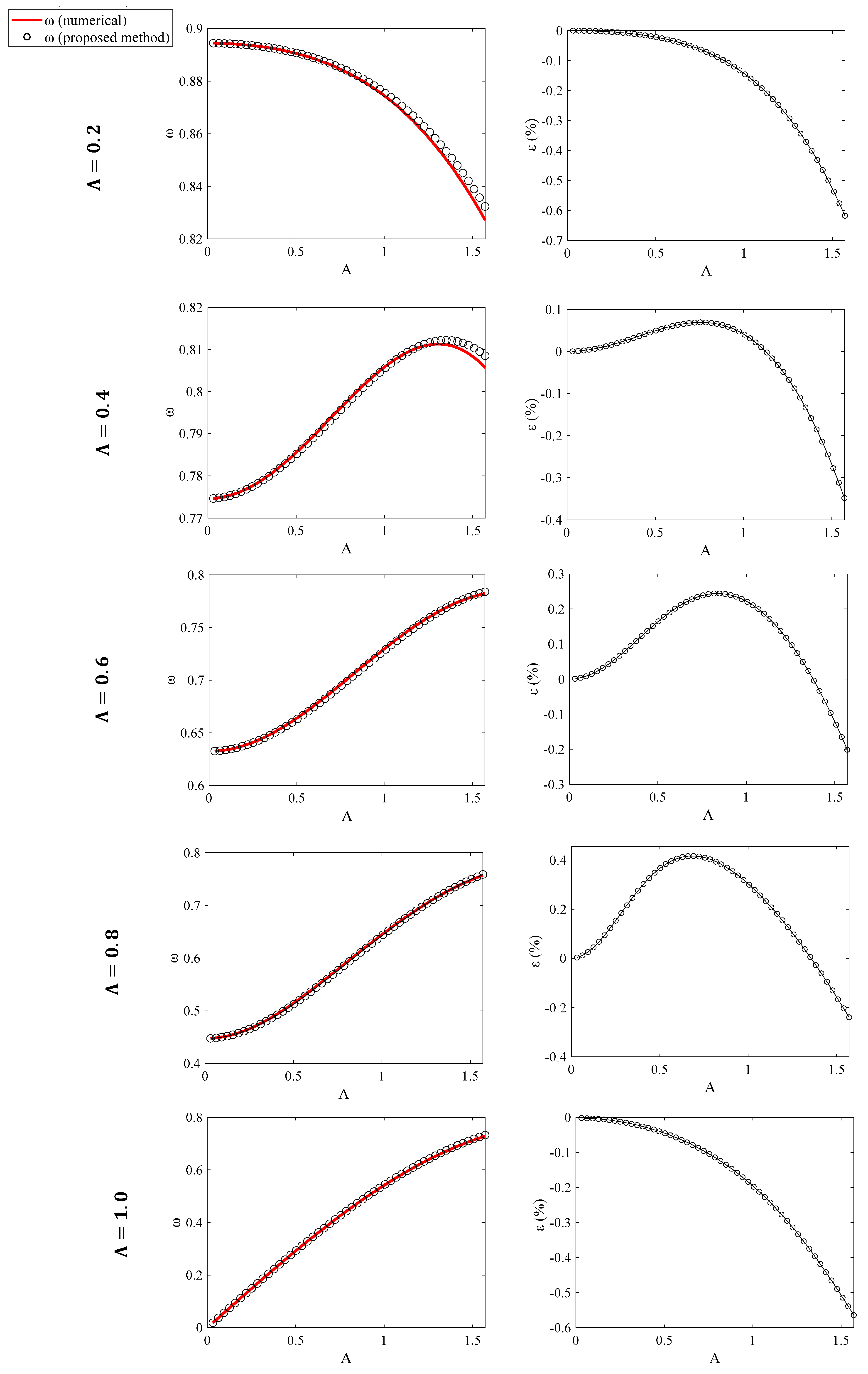
Equation (29) is in the appropriate form to apply to Equation (18). The results obtained using Equations (27), (22), and (18) are presented comparatively in Figure 3 for various values of the parameter Λ ( 0.2 Λ 1.0 ). The amplitudes presented in Figure 3 are in the range π 20 A π 2 . The error was negligible (in any case smaller than 0.62%). The results are also compared with He’s original equations in Table 1.
For the case of the rotating pendulum, Equation (3) can be written as below (since f θ = sin θ Λ 2 sin 2 θ ):
ω H e ( 1 ) = cos A 2 Λ c o s ( A ) .
In addition, Equation (5) is written as follows:
ω H e ( 2 ) = 1 3 cos 0.3 A Λ c o s ( 0.6 A ) + cos 0.5 A Λ c o s ( A ) + cos 0.7 A Λ c o s ( 1.4 A )
The results presented in this paper have additionally been compared with those from other methods, which is worth highlighting [45]. In particular, He et al. used the Homotopy Pertubation Method (HPM) to solve Equation (23) [45]. Two specific cases are presented in this paper. The case with r = 0.6   m ,   Ω = 1.5   r a d / s (where Λ = 0.1378 ) (Table 2 and Figure 4) and the case with r = 1.1   m ,   Ω = 2   r a d / s (where Λ = 0.4490 ) (Table 3 and Figure 5). The values of θ with respect to t, using the accurate numerical results, the HPM (as presented in [45]), and the approximate methods introduced in this paper, are shown comparatively. The trivial solution θ = A c o s ( ω t ) was used for the case of the approximate approach proposed in this paper (where ω is the angular frequency as calculated using Equation (18)). The amplitude of the oscillation was considered as A = 1   r a d in all cases. In addition, the percentage differences between the accurate value of θ and the values calculated using the HPM and the methods presented in this paper are also shown. It is evident from Table 2 and Table 3 and Figure 4 and Figure 5 that the method presented in this paper provides accurate results in every case.

4.2. Electrical Oscillations

In this section, a circuit described by Equations (1) and (2) is presented. This section primarily aims to provide a practical example of an oscillation that can be easily set up in a laboratory using a unique combination of analog integrated circuits (ICs). However, the goal extends beyond merely showcasing a new application of oscillations. It also seeks to present a scenario with real components affected by circuit non-idealities such as noise, mismatch, temperature variations, and offset effects. Demonstrating how to obtain reliable approximate solutions for real-world scenarios significantly underscores the importance of this approach. The following paragraphs outline the implementation details. The initial circuit, depicted in Figure 6, is an analog integrated current-mode differentiator that utilizes a current conveyor transconductance amplifier (CCTA) [47]. By configuring impedance Z 1 as the resistor and impedance Z 2 as the capacitor, this circuit is capable of solving the following equation:
I o u t = τ d I i n d t
The output current is denoted as I o u t , while the input current is represented by I i n . The time constant factor is given by:
τ = I B 1 R 1 C I B 2
Here, I B 1 , I B 2 are the external bias currents for the two CCTA blocks, R 1 is the resistor connected to the X input, and C is the capacitor connected to the corresponding nodes ( Y , O ). In our set up, we utilized an additional differentiator block, identical to the one shown in Figure 6, in series with the first differentiator. Specifically, the input of the second differentiator was connected to the output of the first differentiator to achieve the second derivative of the function. The output of the second differentiator block, as a function of the input to the first differentiator block, is given as follows:
I o u t = τ 2 d 2 I i n d t 2
The second block, consisting of a combination of analog ICs, implements the corresponding part of the polynomial (Equation (2)). The following function is used:
f I i n = a   I i n + β I i n 3 + γ I i n 5 ,
where a = 1 2 ,   β = 1 6   and   γ = 7 120 . The implementation of the multiplication of I i n with parameters α , β , γ using analog ICs is illustrated in Figure 7. An analog multiplier [48] is utilized to achieve this. Additionally, the multiplication factor α , β , γ is approximated with the tuning of the normalized current I n o r m for each case. The transistor-level implementation of the analog integrated multiplier is shown in Figure 8. Based on translinear principle [49,50], the mathematical equation which describes its behaviour is given as follows:
I o u t = I b i a s I b I m u l
As a result, the equation which describes the multiplication (division between numerator and denominator) is given as follows:
I o u t = I n o r m I i n x I d e n
where x = 1 , 3 , 5 and I n o r m I d e n is the related parameter α , β , γ .
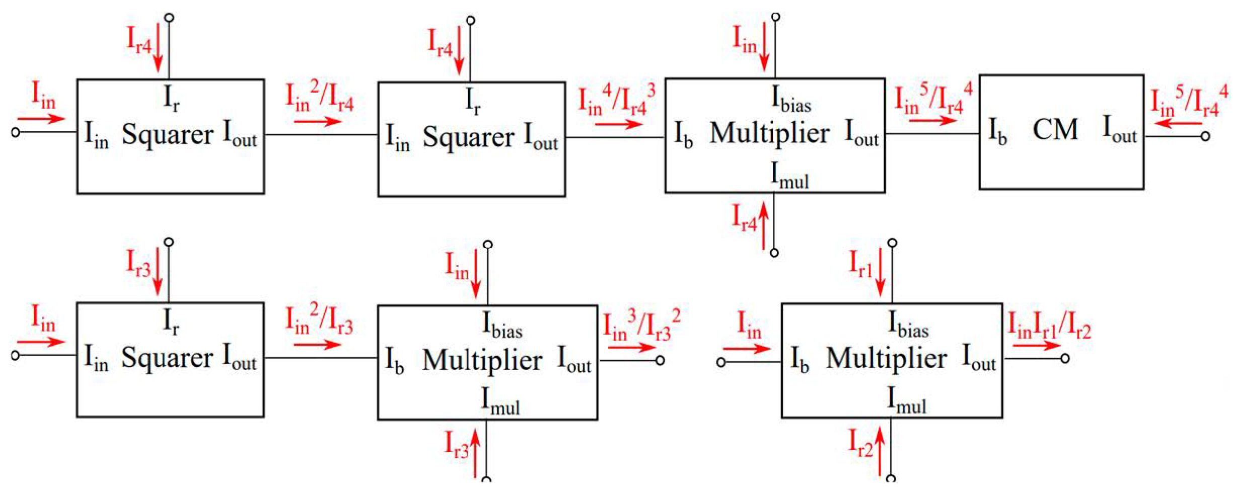
Since x = 1 ,   3 ,   5 , we need five multipliers to implement the 5th order case. To reduce the required hardware, the squarer shown in Figure 9 is introduced. The squarer circuit [50] is based on translinear principles [49] and the equation that describes its behaviour is given as follows:
I o u t = I i n 2 I r
Since Figure 10 is a current mode implementation, by connecting the output nodes, we can conclude in the following equation:
f I i n = I i n I r 1 I r 2 + I i n 3 I r 3 2 I i n 5 I r 4 4 .
The use of an extra current mirror (CM) circuit changes the sign (from plus to minus).
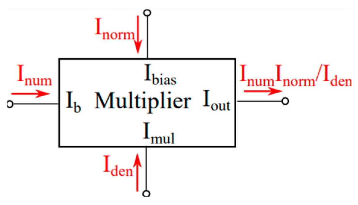
Since the 3rd and 5th order terms of f I i n are not normalized (Equation (34)), we use an alternative current-mode multiplier to achieve the necessary multiplications with the normalized current (Figure 11). Based on translinear principle [49,50,51], the mathematical equation which describes its behaviour is given as follows:
I o u t = k I x I y
where k is a normalized circuit parameter.
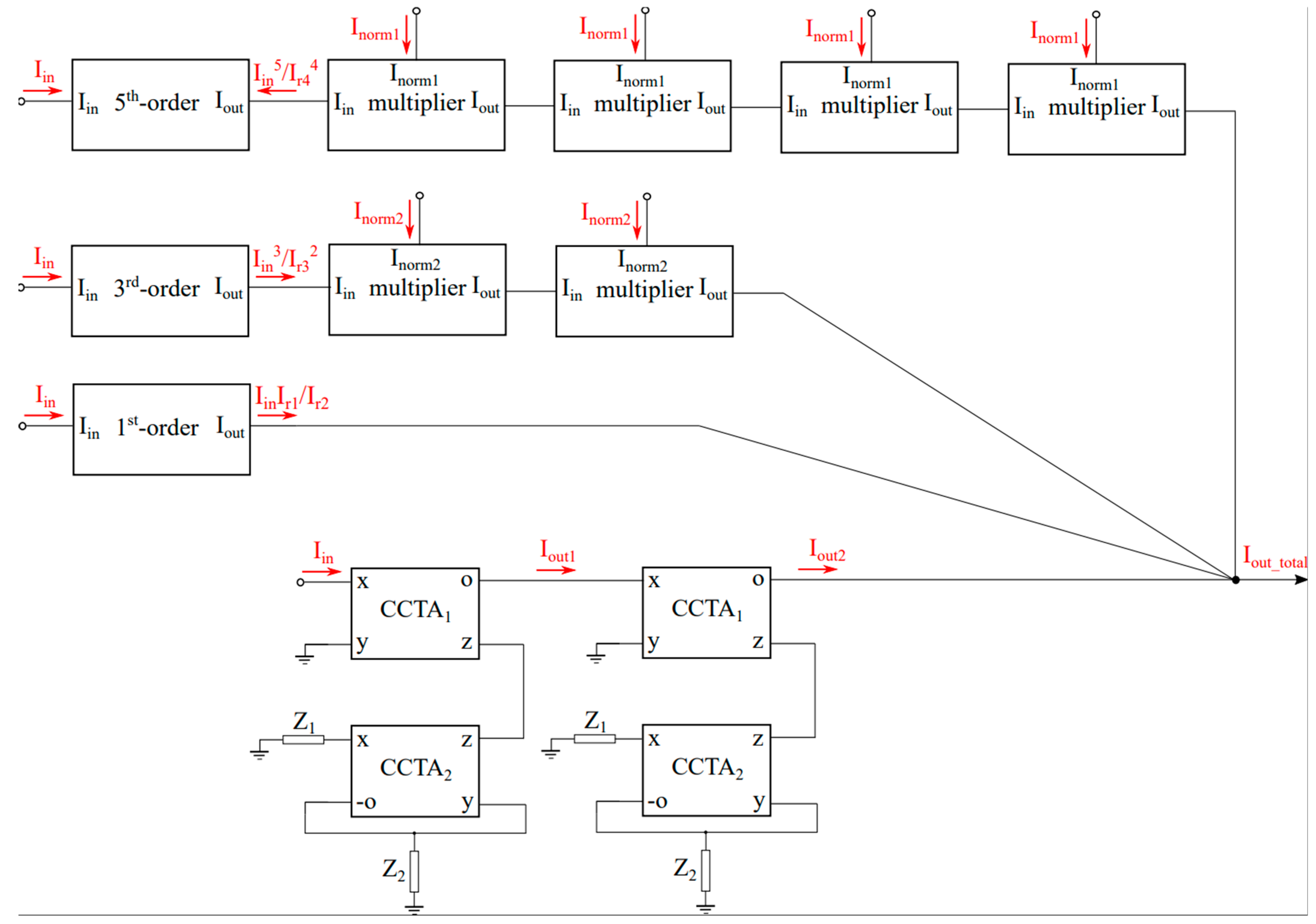
The high-level implementation of the differential equation is shown in Figure 12. It consists of both terms. One extra point here is that we have multiplied the output current of each term (3rd and 5th order) with the normalized currents provided by the alternative multipliers. Extra CMs are used to convert the sign in the differential equation. More specifically, the resulting equation is as follows:
τ 2 d 2 I i n d t 2 + I i n I r 1 I r 2 + I i n 3 I r 3 2 I n o r m 2 2 I i n 5 I r 4 4 I n o r m 1 4 = 0
For the specific application the differential equation is as follows:
d 2 I i n d t 2 + 1 2 I i n + 1 6 I i n 3 7 120 I i n 5 = 0
We can easily compare the related Equations (40) and (41) to find the parameter currents. For τ = 1 , we can easily calculate the related currents: I r 1 = 1 2 I r 2 = 100   n A , I n o r m 2 = 1 6 I r 3 = 20   n A , and I n o r m 1 = 2.0306 I r 4 = 70   n A . In Table 4, the angular frequency calculated for the electrical analog, along with the accurate numerical results of Equation (42) and the results from the proposed by this paper equation, are shown. The values of the current that were used were in the range 0.1 I i n 1   ( μ A ) . There is a percentage difference of approximately 0.2–4% between the results provided by the circuit and the accurate numerical results. This is an expected result because, as previously mentioned, the high-level implementation of the realized blocks was conducted using real components, which entail non-idealities. However, the differences are small; therefore, the equations presented in this paper provide accurate results for real-world applications.

5. The 9th Degree Polynomial Case

An alternative method for addressing various applications involving polynomial-type restoring forces is also presented below. Consider, for example, a differential equation in the form of Equations (1) and (2), with a 9th degree polynomial restoring force, as follows:
d 2 x d t 2 + c 0 x + c 1 x 3 + c 2 x 5 + c 3 x 7 + c 4 x 9 = 0
By considering a trivial solution of the form x = A c o s ( ω t ) for the differential Equation (43) and using the series expansion of the trigonometric functions while omitting the terms higher than the first order, the following is concluded [11,52]:
ω 2 A cos ω t + c 1 A cos ω t + c 2 A 3 cos 3 ω t + c 3 A 5 cos 5 ω t + c 4 A 7 cos 7 ω t + c 5 A 8 cos 9 ω t = 0
ω f o u r i e r = c 0 + 3 4 c 1 A 2 + 5 8 c 2 A 4 + 35 64 c 3 A 6 + 63 128 c 4 A 8
Equation (44) is a classic equation that has also been derived through various approaches in the literature. Liu employed He’s variational method to derive Equation (44) [53]. Yazdi et al. used He’s Max–Min Approach and obtained the exact same equation [54]. Similarly, Younesian et al. [55] applied He’s frequency–amplitude formulation and also derived Equation (44). Numerous other studies have reached the same conclusion (e.g., [56,57]). This reflects a strong interest within the nonlinear science community in developing methods that yield simple, practical equations for approximating oscillation frequencies. However, Equation (44) has been proven to be accurate only for small oscillation amplitudes [52,53,54,55,56,57]. To demonstrate this, the results obtained using Equations (18) and (44), with all coefficients set to unity ( c 0 = c 1 = = c 4 = 1 ), along with the exact numerical results, are presented in Figure 13a. The percentage differences between the accurate numerical results, the proposed approach (Equation (18)), and the results provided by Equation (44) are presented in Figure 13b. Only the proposed approach yields excellent results for large amplitudes.
This result is further demonstrated in Table 5, where very large amplitudes are considered. ε 1 ( % ) represents the error when using Equation (44), while ε 2 ( % ) represents the error when using the proposed equation (Equation (18)). Only Equation (18) yields accurate results for large amplitudes.
It is also worth discussing the rationale behind the proposed equations (Equations (13)–(18)). Various methods [11,39,52,53,54,55,56,57] have demonstrated that the angular frequency of an oscillator with an odd m-degree polynomial-type restoring force can be approximated by a generic equation of the form:
ω = c 0 + β 1 c 1 A 2 + β 2 c 2 A 4 + + β n c n A m 1
where β 1 , β 2 , , β n are constants that need to be determined. For A 1 , ω c 0 , which is the case of simple harmonic motion.
For A 1 , and similar values of the c-coefficients, the term with the highest power in the polynomial given by Equation (2) becomes dominant. For example, if c 0 = c 1 = c 2 = = c n = 1 , the highest-order term becomes dominant, and Equation (45) simplifies as follows:
ω β n c n A m 1
However, Equation (46) is similar to Equation (8) under the following condition:
β n = π m + 1 2 Γ 3 + m 2 ( m + 1 ) Γ 1 m + 1
Therefore, the main idea behind this paper is to consider that all the β-coefficients are given by the equation above ( β n = m λ m as already explained in Section 2). In addition, this is the reason why, for A = 1, the error is the largest in all cases. In this scenario, no dominant factor exists. However, even in this case, the error remains small compared to other solutions. For a 9th-degree polynomial, the error is 1.66% when using Equation (18), which is lower than the 2.94% error provided by the classic Equation (44).

6. Discussion and Further Considerations

In this paper, a new equation for solving nonlinear oscillations with an odd polynomial restoring force is presented. The idea was to combine He’s equation [39] with the equation for a power-law restoring force [44] to derive an accurate formula for determining the oscillation’s angular frequency, regardless of its amplitude. It was shown that the proposed approach (which leads to Equation (11)) provides an accurate solution for any odd polynomial-type restoring force, regardless of whether it exhibits ‘hardening’ or ‘softening’ behaviour. To test both ‘hardening’ and ‘softening’ behaviours, a rotating pendulum was used as an example, as it exhibits both behaviours depending on the angular frequency. The results of the proposed approach were accurate in all cases. In addition, special attention should be given to the examples presented concerning the rotating pendulum. The cases that were studied were for 0 < θ 0 π / 2 and Λ 1 in order to ensure an oscillation around the equilibrium position θ = 0 . For example, consider the case with Λ = 1 . By setting the restoring force in Equation (25) to zero, the following equation is obtained:
sin θ + 1 2 sin 2 θ = 0
Equation (48) is a trigonometric equation with the following solution:
θ = κ π ,   κ Ζ .
Therefore, for the domain π / 2 θ π / 2 , F θ = 0 for κ = 0   ( i . e . , θ = 0 ) . In addition, as presented in Figure 14a, for θ > 0 , F θ < 0 . Therefore, the criteria for oscillatory motion are fulfilled. On the contrary, considering Λ = 1.1 , Equation (48) yields the following:
sin θ + 1.1 2 sin 2 θ = 0
Equation (50) has the following set of solutions:
θ 1 = κ π θ 2 = 2 κ π cos 1 10 11 θ 3 = 2 κ π + cos 1 10 11 ,   κ Ζ
For κ = 0 , Equation (51) results in θ 1 = 0 , θ 2 = 0.4297   r a d , and θ 3 = 0.4297   r a d . Therefore, in this case, there are three equilibrium positions (positions where F θ = 0 in the domain π / 2 θ π / 2 ). It is noteworthy that for Λ > 1 , θ > 0 , F θ > 0 near θ = 0 . Therefore, cases with small displacements ‘around the position θ = 0 ’ were not considered since they do not meet the criteria for an oscillatory motion. In these cases, the methods as presented in this paper are not valid. In Figure 14, the restoring force F with respect to the angular displacement θ (Figure 14a) and the potential energy U with respect to θ (Figure 14b) are presented comparatively for Λ = 0.8 ,   1 ,   1.2 .
The equations presented in this paper have applications beyond the rotating pendulum, polynomial restoring forces, and electrical oscillators. Another important example is oscillation with cubic and harmonic restoring forces. This is an example of tremendous importance, as it can describe nearly any undamped nonlinear oscillator [35,36]. Therefore, consider the following case:
d 2 x d t 2 + x + x 3 + sin x = 0
The term sin(x) can be expressed as a Maclaurin series:
sin x = x x 3 3 ! + x 5 5 ! x 7 7 ! + x 9 9 ! = x x 3 6 + x 5 120 x 7 5040 + x 9 362,880
Therefore, Equation (52) is modified as below:
d 2 x d t 2 + 2 + 5 x 3 6 + x 5 120 x 7 5040 + x 9 362,880 = 0
where c 0 = 2 , c 1 = 5 / 6 , c 2 = 1 / 120 , c 3 = 1 / 5040 , and c 4 = 1 / 362,880 . The accurate numerical results can be determined as follows. By integrating Equation (52) and considering x(0) = A and x′(0) = 0:
1 2 d x d t 2 + x 2 2 + x 4 4 cos x = A 2 2 + A 4 4 cos A
Therefore,
T = 4 0 A 1 A 2 + A 4 2 2 cos A x 2 x 4 2 + 2 cos x d x
Thus, the accurate equation for the angular frequency, which can be solved numerically, is as follows:
ω n u m . = 2 π 4 0 A 1 A 2 + A 4 2 2 cos A x 2 x 4 2 + 2 cos x d x
For A = 3 , 4 and 5, we obtain: ω n u m . ( A = 3 ) = 2.788 , ω n u m . ( A = 4 ) = 3.541 , and ω n u m . ( A = 5 ) = 4.345 . In addition, the results provided by the proposed equation (Equation (18)) are as follows: ω ( A = 3 ) = 2.775 , ω ( A = 4 ) = 3.530 , and ω ( A = 5 ) = 4.343 . For A = 3, the percentage difference is 0.468%, while for A = 4 and A = 5, the percentage differences between the accurate and numerical results are 0.312% and 0.046%, respectively. Our objective here is to highlight that in any case of a nonlinear oscillation where the restoring force can be approximated by a Maclaurin series, Equation (13) can be reliably utilized to determine the angular frequency for any amplitude. Additional applications include the simple pendulum, the capillary oscillator, the tangent oscillator, and the hyperbolic tangent oscillator, among others [11,36,37,40,41,58].
It is also worth emphasizing that in the case of nonlinear oscillations with a polynomial-type restoring force, the accurate solution for the oscillation’s period (and consequently the angular frequency) is expressed in integral form and can be solved numerically. This information has already been incorporated into the manuscript (Equation (21)), as we utilized these numerical results for comparison with our method. However, while the numerical solution is straightforward to implement, it has notable drawbacks. Specifically, a large number of cases must be solved numerically to evaluate how different variables influence the final results. Even with such an approach, the resulting equations may yield accurate outcomes for a specific domain but often include coefficients without physical significance. Here is an example to illustrate this point. Consider a polynomial restoring force of the 9th degree. In this scenario, the angular frequency can be readily calculated numerically as follows:
ω n u m . = 2 π Τ n u m , = 2 π 4 0 A 1 c 0 A 2 + c 1 A 4 2 + c 2 A 6 3 + c 3 A 8 4 + c 4 A 10 5 ( c 0 x 2 + c 1 x 4 2 + c 2 x 6 3 + c 3 x 8 4 + c 4 x 10 5 ) d x
For a specified amplitude (e.g., A = 3) and with c 0 = c 1 = c 2 = c 3 = c 4 = 1 , solving the integral of the above equation numerically to find the angular frequency is straightforward. However, how can we establish the relationship between ω and A? To do so, we would need to analyse hundreds or even thousands of cases with varying amplitudes, create tables of ω and A, and then apply fitting procedures to derive an equation. This equation would likely contain fitting constants that lack physical significance. Furthermore, it is most probable that this numerically derived equation would only be valid within a specific range and not as A . The problem becomes even more challenging when considering arbitrary values for the c-coefficients. The data for ω and A will vary when the coefficients change, making it impossible to derive an accurate analytical expression solely from numerical integral solutions. For this reason, many approximate analytical equations have been developed over the past few decades to estimate the frequency of nonlinear oscillations, as discussed in the introduction and further elaborated upon in the discussion of this manuscript.
It is also interesting to discuss the convergence issues of the proposed equations. Two separate cases will be considered. The first is related to cases in which a Maclaurin series expansion is used to replace f(x) in Equation (1) (e.g., the rotating pendulum in Section 4.1). In these cases, it should be t n + 1 t n < 1 and l i m A 0 t n + 1 t n 0 , where ‘ t n ’ is the n t h term in the series. It can be easily shown that the criteria above are satisfied for the case of the rotating pendulum examined in Section 4.1. The second case is related to differential equations in which f(x) is a specific polynomial with a finite number of terms (not approximated by a polynomial using a Maclaurin series). For example, consider the case of Equation (43). In this case, the equation for the angular frequency will also have a finite number of terms (the same number of terms as the polynomial, which is five in the case of Equation (43)) and will always converge.
Special attention should also be given to the electrical analogue of the oscillation with odd polynomial-type restoring force. Recently, there has been a growing trend in the adoption of low-power analog integrated circuits (ICs) across various domains. Beyond their established uses in signal processing, sensor inference, power management, communication systems, and automotive applications [59,60,61,62,63], these ICs are increasingly being explored for machine learning (ML) applications [64,65,66,67,68,69,70]. Their versatility in processing and representing information has facilitated this expansion. This development is attributed to the ability to model many ML algorithms and models using mathematical equations that are compatible with analog ICs. Analog computing traditionally involves employing continuous signals, such as voltages and currents, to simulate physical processes through fundamental operations like addition, multiplication, differentiation, and integration [70,71,72,73,74,75,76]. Interestingly, electromechanical analogies were first utilized in reverse to describe electrical phenomena through well-known mechanical terms. Nowadays, electric phenomena are fully understood, and an electrical analogy can serve as a simple way to model mechanical systems, physical phenomena, or mathematical problems that do not have analytical solutions. This approach makes it easy to find correlations between different magnitudes involved in the system and to arrive at accurate numerical solutions, even when using real (i.e., non-ideal) components. In conclusion, the novel key findings of this paper are summarized as follows:
  • A simple equation (Equation (11)) was derived that can be used to approximate the angular frequency of any undamped nonlinear oscillation with an m-degree odd-power polynomial restoring force.
  • The proposed equation can be applied regardless of the oscillation’s amplitude, as demonstrated in Section 3.
  • It is valid for both ’hardening’ and ’softening’ systems, as shown in the example of the rotating pendulum (Section 4.1).
  • It can be used for real industrial applications (e.g., electrical oscillations in Section 4.2).
  • It provides significantly more accurate results for large amplitudes compared to classic equations in the literature (e.g., Equation (44)).
  • It is a valuable method for solving many classic systems, such as the simple pendulum, the capillary oscillator, and the oscillator with cubic and harmonic restoring forces, among others, since in the aforementioned cases, the restoring force can be written in the form of an m-degree odd-power polynomial using a Maclaurin series expansion.
Another important point to discuss is the limitations of the equations provided by this paper. In particular, Equations (1) and (2) can be used for most undamped nonlinear oscillators; however, there are also significant cases that cannot be modelled by them. A significant case is the Helmholtz–Duffing oscillator, a distinctive problem in nonlinear dynamics, engineering, and science due to the presence of both quadratic and cubic nonlinear terms [77]. Another case in which the methods presented in this paper cannot be used is related to a restoring force with a magnitude that combines odd and even exponents, and it can be described by the generic differential equation below [44]:
d 2 x d t 2 + c 0 x + c 1 x x + = 0
However, despite these restrictions, Equations (1) and (2) can be used in most cases of undamped nonlinear oscillations, as already discussed in the introduction, making the equations presented in this paper a valuable tool for research in nonlinear science. Therefore, as future research, an extension of the proposed equation to also include these cases should be considered. Another interesting case is one in which, along with the restoring force, there is also a damping term and an external periodic force. It has already been shown that for the case of the damped Duffing oscillator, He’s approach can lead to reliable approximate solutions for small amplitudes [78]. Therefore, it is interesting to investigate whether the analysis presented in this paper, for m-degree odd-power polynomial restoring force, can be used to approximate the behaviour of damped and driven oscillator systems within a specific range of amplitudes.

7. Conclusions

In this paper, a novel and straightforward equation (Equation (11)) is derived to approximate the angular frequency of any undamped nonlinear oscillation governed by an m-degree odd-power polynomial restoring force. The proposed equation is valid for any oscillation amplitude, as demonstrated in Section 3, and is applicable to both hardening and softening systems, as shown in the case of the rotating pendulum (Section 4.1). Furthermore, its relevance to real industrial applications, such as electrical oscillations (Section 4.2), highlights its practical significance. Notably, the equation provides significantly improved accuracy for large amplitudes compared to classical approaches, such as Equation (44). Additionally, its versatility allows for solving various well-known nonlinear systems, including the simple pendulum, the capillary oscillator, and oscillators with cubic and harmonic restoring forces. In these cases, the restoring force can be expressed as an m-degree odd-power polynomial using a Maclaurin series expansion. These findings demonstrate the effectiveness and broad applicability of the proposed method in nonlinear dynamics. In conclusion, the study of nonlinear oscillations presents significant challenges, primarily due to the absence of analytical solutions for the associated differential equations. This paper effectively addresses these challenges by deriving a universal equation that accurately characterizes oscillations across all amplitudes for systems with odd-power polynomial restoring forces. Overall, this work provides valuable insights into the field of nonlinear dynamics and opens new avenues for further research and applications in engineering practices.

Author Contributions

Conceptualization, S.V.K., G.M.I., and A.M.; methodology, S.V.K., G.M.I., and A.M.; software, S.V.K., G.M.I., V.A., C.D., and A.M.; validation, S.V.K., G.M.I., V.A., C.D., and A.M.; investigation, S.V.K., G.M.I., V.A., C.D., and A.M.; resources, S.V.K., G.M.I., V.A., C.D., and A.M.; writing—original draft preparation, S.V.K., G.M.I., and V.A.; writing—review and editing, S.V.K., G.M.I., V.A., and A.M. All authors have read and agreed to the published version of the manuscript.

Funding

This research received no external funding.

Data Availability Statement

The original contributions presented in this study are included in the article. Further inquiries can be directed to the corresponding authors.

Conflicts of Interest

The authors declare no conflicts of interest.

Appendix A

The purpose of this part is to derive the equation of motion of a simple pendulum with a fixed arm length r on one end, attached to a mass m on the other end, in a rotating axis formed by a rigid rod. To help us see the movement, we think about two Cartesian coordinate systems where the first O x y z stays still in space and the other O x y z moves with the body and rotates with it, as shown in Figure A1. The rod is linked to a rotating rigid structure moving at a steady angular speed Ω = φ ˙ around the vertical axes O y and O y . In this case, φ represents the amount of rotation of the Oxyz rotary frame around the vertical axis O y .
Figure A1. Dynamical model of the motion of a simple pendulum.
Dynamics 05 00009 g0a1
From Figure A1, we have
x = r c o s θ ,   y = l r c o s θ ,   z = 0
Hence, we can write
z = z c o s φ x s i n φ ,   x = x c o s φ + z s i n φ
In Equation (A1), θ represents the angle at which the T-shaped object is inclined from the vertical axis, while l indicates the distance from the pendulum’s rotating axis (rigid rod) to the z-axis. From the information provided above, it is simple to acquire:
x = r s i n θ   c o s φ ,   x = l r   c o s φ ,   z = r s i n θ   s i n φ
Using the aforementioned projections of point p onto the Oxyz coordinate system, we can express the kinetic and potential energies as follows:
K = 1 2 m r 2 ( θ ˙ 2 + Ω 2 s i n 2 θ ) , U = m g 1 r c o s θ
The dots represent the derivative with respect to time t and g is the acceleration due to gravity. As per the variational theory [45,79,80,81], the Lagrange’s equation describes conservative dynamical systems:
d d t L θ ˙ L θ = 0
where L = K U is the Lagrangian. The equation of motion therefore has the form
r g d 2 θ d t 2 + 1 Λ c o s θ s i n θ = 0
where Λ = Ω 2 r g . Now, we present a new independent variable t in the following format:
τ = g r t
According to Equation (A7), the equation of motion can be reformulated as follows:
d 2 θ d t 2 + 1 Λ c o s θ s i n θ = 0
where primes represent the derivative with respect to time t.

References

  1. Abouelregal, A.E.; Mohammad-Sedighi, H.; Faghidian, S.A.; Shirazi, A.H. Temperature-dependent physical characteristics of the rotating nonlocal nanobeams subject to a varying heat source and a dynamic load. Facta Univ. Ser. Mech. 2021, 19, 633–656. [Google Scholar] [CrossRef]
  2. Sedighi, H.M.; Shirazi, K.H. Dynamic pull-in instability of double-sided actuated nano-torsional switches. Acta Mech. Solida Sin. 2015, 28, 91–101. [Google Scholar] [CrossRef]
  3. Anjum, N.; He, J.H. Two modifications of the homotopy perturbation method for nonlinear oscillators. J. Appl. Comput. Mech. 2020, 6, 1420–1425. [Google Scholar]
  4. Anjum, N.; He, J.H. Homotopy perturbation method for N/MEMS oscillators. Math. Meth. Appl. Sci. 2020, 2020, 1–15. [Google Scholar] [CrossRef]
  5. Anjum, N.; He, J.H. Higher-order homotopy perturbation method for conservative nonlinear oscillators generally and microelectromechanical systems’ oscillators particularly. Int. J. Mod. Phys. 2020, 34, 2050313. [Google Scholar] [CrossRef]
  6. Qie, N.; Houa, W.F.; He, J.H. The fastest insight into the large amplitude vibration of a string. Rep. Mech. Eng. 2021, 2, 1–5. [Google Scholar] [CrossRef]
  7. Hosen, M.A.; Chowdhury, M.S.H. A new reliable analytical solution for strongly nonlinear oscillator with cubic and harmonic restoring force. Results Phys. 2015, 5, 111–114. [Google Scholar] [CrossRef]
  8. Kontomaris, S.V.; Malamou, A. Exploring oscillations with a nonlinear restoring force. Eur. J. Phys. 2022, 43, 015006. [Google Scholar] [CrossRef]
  9. Xu, L. Application of He’s parameter-expansion method to an oscillation of a mass attached to a stretched elastic wire. Phys. Lett. A 2007, 368, 259–262. [Google Scholar] [CrossRef]
  10. Li, S.; Niu, J.; Li, X. Primary resonance of fractional-order Duffing–van der Pol oscillator by harmonic balance method. Chin. Phys. B 2018, 27, 120502. [Google Scholar] [CrossRef]
  11. Kontomaris, S.V.; Mazi, I.; Malamou, A. A Note on a Simple Equation for Solving Nonlinear Undamped Oscillations. J. Vib. Eng. Technol. 2024, 12, 8235–8248. [Google Scholar]
  12. Ju, P.; Xue, X. Global residue harmonic balance method to periodic solutions of a class of strongly nonlinear oscillators. Appl. Math. Model. 2014, 38, 6144–6152. [Google Scholar]
  13. Wu, B.; Liu, W.; Chen, X.; Lim, C.W. Asymptotic analysis and accurate approximate solutions for strongly nonlinear conservative symmetric oscillators. Appl. Math. Model. 2017, 49, 243–254. [Google Scholar]
  14. He, J.H.; Yang, Q.; He, C.H.; Khan, Y. A simple frequency formulation for the tangent oscillator. Axioms 2021, 10, 320. [Google Scholar] [CrossRef]
  15. Tian, Y. Frequency formula for a class of fractal vibration system. Rep. Mech. Eng. 2022, 3, 55–61. [Google Scholar]
  16. Mickens, R.E. A generalization of the method of harmonic balance. J. Sound Vib. 1986, 111, 515–518. [Google Scholar]
  17. Mickens, R.E. Truly Nonlinear Oscillations; World Scientific Publishing: Singapore, 2010. [Google Scholar]
  18. He, J.H.; Wu, X.H. Variational iteration method: New development and applications. Comput. Math. Appl. 2007, 54, 881–894. [Google Scholar]
  19. Wu, H.G.; Hu, Y. On variational iteration method for fractional calculus. Therm. Sci. 2017, 21, 1707–1712. [Google Scholar]
  20. Liao, S.J.; Cheung, A.T. Application of homotopy analysis method in nonlinear oscillations. ASME J. Appl. Mech. 1998, 65, 914–922. [Google Scholar]
  21. Zhang, G.Q.; Wu, Z.Q. Homotopy analysis method for approximations of Duffing oscillator with dual frequency excitations. Chaos Soliton Fract. 2019, 127, 342–353. [Google Scholar]
  22. Wu, Y.; He, J.H. Homotopy perturbation method for nonlinear oscillators with coordinate-dependent mass. Results Phys. 2018, 10, 270–271. [Google Scholar]
  23. He, J.H.; El-Dib, Y.O.; Mady, A.A. Homotopy perturbation method for the fractal Toda oscillator. Fractal Fract. 2021, 5, 93. [Google Scholar] [CrossRef]
  24. Anjum, N.; He, J.H.; Ain, Q.T.; Tian, D. Li–He’s modified homotopy perturbation method for doubly-clamped electrically actuated microbeams-based microelectromechanical system. Facta Univ. Ser. Mech. 2021, 19, 601–612. [Google Scholar]
  25. He, J.H.; El-Dib, Y.O. The enhanced homotopy perturbation method for axial vibration of strings. Facta Univ. Ser. Mech. 2021, 19, 735–750. [Google Scholar]
  26. Belendez, A.; Hernandez, A.; Belendez, T. Asymptotic representation of the period for the nonlinear oscillator. J. Sound Vib. 2007, 299, 403–408. [Google Scholar]
  27. Cveticanin, L.; Kovacic, I.; Rakaric, Z. Asymptotic methods for vibrations of the pure non-integer order oscillator. Comput. Math. Appl. 2010, 60, 2616–2628. [Google Scholar]
  28. Molla, M.H.U.; Alam, M.S. Higher accuracy analytical approximations to nonlinear oscillators with discontinuity by energy balance method. Results Phys. 2017, 7, 2104–2110. [Google Scholar]
  29. Ebaid, A.E. Approximate periodic solutions for the non-linear relativistic harmonic oscillator via differential transformation method. Commun. Nonlinear Sci. Numer. Simul. 2010, 15, 1921–1927. [Google Scholar]
  30. Wang, S.Q.; He, J.H. Nonlinear oscillator with discontinuity by parameter expansion method. Chaos Soliton Fract. 2008, 35, 688–691. [Google Scholar]
  31. Sedighi, H.M.; Shirazi, K.H.; Noghrehabadi, A.R.; Yildirim, A.H.M.E.T. Asymptotic investigation of buckled beam nonlinear vibration. Iran. J. Sci. Technol. Trans. Mech. Eng. 2012, 36, 107–116. [Google Scholar]
  32. He, J.H.; Anjum, N.; Skrzypacz, P. A variational principle for a nonlinear oscillator arising in the microelectromechanical system. J. Appl. Comput. Mech. 2021, 7, 78–83. [Google Scholar]
  33. He, J.H.; Houa, W.F.; Qie, N.; Gepreel, K.A.; Shirazi, A.H.; Mohammad-Sedighi, H. Hamiltonian-based frequency-amplitude formulation for nonlinear oscillators. Facta Univ. Ser. Mech. 2021, 19, 199–208. [Google Scholar] [CrossRef]
  34. Hosen, M.A.; Ismail, G.M.; Yildirim, A.; Kamal, M.A.S. A modified energy balance method to obtain higher-order approximations to the oscillators with cubic and harmonic restoring force. J. Appl. Comput. Mech. 2020, 6, 320–331. [Google Scholar]
  35. El-Dib, Y.O.; Matoog, R.T. The rank upgrading technique for a harmonic restoring force of nonlinear oscillators. J. Appl. Comput. Mech. 2021, 7, 782–789. [Google Scholar]
  36. Kontomaris, S.V.; Mazi, I.; Chliveros, G.; Malamou, A. Generic numerical and analytical methods for solving nonlinear oscillators. Phys. Scr. 2024, 99, 025231. [Google Scholar] [CrossRef]
  37. Lu, J. Global residue harmonic balance method for strongly nonlinear oscillator with cubic and harmonic restoring force. J. Low Freq. Noise Vib. Act. Control 2022, 41, 1402–1410. [Google Scholar] [CrossRef]
  38. Big-Alabo, A. Approximate periodic solution for the large-amplitude oscillations of a simple pendulum. Int. J. Mech. Eng. Educ. 2020, 48, 335–350. [Google Scholar] [CrossRef]
  39. He, J.H. The simplest approach to nonlinear oscillators. Results Phys. 2019, 15, 102546. [Google Scholar] [CrossRef]
  40. Chen, B.; Lu, J.; Xia, Z. Numerical investigation of the fractal capillary oscillator. J. Low Freq. Noise Vib. Act. Control 2023, 42, 579–588. [Google Scholar] [CrossRef]
  41. Jin, X.; Liu, M.; Pan, F.; Li, Y.; Fan, J. Low frequency of a deforming capillary vibration, part 1: Mathematical model. J. Low Freq. Noise Vib. Act. Control 2019, 38, 1676–1680. [Google Scholar] [CrossRef]
  42. Kontomaris, S.V.; Chliveros, G.; Malamou, A. Approximate Solutions for Undamped Nonlinear Oscillations Using He’s Formulation. J 2023, 6, 140–151. [Google Scholar] [CrossRef]
  43. Kauderer, H. Nichtlineare Mechanik; Springer: Berlin/Göttingen/Heidelberg, Germany, 1958. [Google Scholar]
  44. Cveticanin, L. Oscillator with Fractional Order Restoring Force. J. Sound Vib. 2009, 320, 1064–1077. [Google Scholar] [CrossRef]
  45. He, J.-H.; Amer, T.S.; Elnaggar, S.; Galal, A.A. Periodic property and instability of a rotating pendulum system. Axioms 2021, 10, 191. [Google Scholar] [CrossRef]
  46. Ismail, G.M.; El-Moshneb, M.M.; Zayed, M. Analytical technique for solving strongly nonlinear oscillator differential equations. Alex. Eng. J. 2023, 74, 547–557. [Google Scholar] [CrossRef]
  47. Srisoontorn, S.; Charoenmee, A.; Panikhom, S.; Janda, T.; Fungdetch, S.; Patimaprakorn, K.; Jantakun, A. Reconfigurable current-mode differentiator and integrator based on current conveyor transconductance amplifiers. Int. J. Electr. Comput. Eng. 2022, 12, 208–218. [Google Scholar] [CrossRef]
  48. Alimisis, V.; Gennis, G.; Gourdouparis, M.; Dimas, C.; Sotiriadis, P.P. A low-power analog integrated implementation of the support vector machine algorithm with on-chip learning tested on a bearing fault application. Sensors 2023, 23, 3978. [Google Scholar] [CrossRef]
  49. Gilbert, B. Translinear circuits: An historical overview. Analog Integr. Circuits Signal Process. 1996, 9, 95–118. [Google Scholar] [CrossRef]
  50. Al-Tamimi, K.M.; Al-Absi, M.A. An ultra low power high accuracy current-mode CMOS squaring circuit. In Proceedings of the World Congress on Engineering and Computer Science, San Francisco, CA, USA, 24–26 October 2012; Volume 2. [Google Scholar]
  51. Alimisis, V.; Eleftheriou, N.P.; Kamperi, A.; Gennis, G.; Dimas, C.; Sotiriadis, P.P. A radar-based system for detection of human fall utilizing analog hardware architectures of decision tree model. IEEE Open J. Circuits Syst. 2024, 5, 224–242. [Google Scholar] [CrossRef]
  52. Cveticanin, L.; Ismail, G.M. Higher-order approximate periodic solution for the oscillator with strong nonlinearity of polynomial type. Eur. Phys. J. Plus 2019, 134, 266. [Google Scholar] [CrossRef]
  53. Liu, J.F. He’s variational approach for nonlinear oscillators with high nonlinearity. Comput. Math. Appl. 2009, 58, 2423–2426. [Google Scholar] [CrossRef]
  54. Yazdi, M.K.; Ahmadian, H.; Mirzabeigy, A.; Yildirim, A. Dynamic analysis of vibrating systems with nonlinearities. Commun. Theor. Phys. 2012, 57, 183–187. [Google Scholar]
  55. Younesian, D.; Askari, H.; Saadatnia, Z.; Kalami Yazdi, M. Frequency analysis of strongly nonlinear generalized Duffing oscillators using He’s frequency-amplitude formulation and He’s energy balance method. Comput. Math. Appl. 2010, 59, 3222–3228. [Google Scholar]
  56. Ren, Z.F.; Hu, G.F. He’s frequency-amplitude formulation with average residuals for nonlinear oscillators. J. Low Freq. Noise Vib. Act. Control 2019, 38, 1050–1059. [Google Scholar]
  57. Qian, Y.; Ren, D.; Chen, S.; Ping, L. Homotopy analysis method for large-amplitude free vibrations of strongly nonlinear generalized Duffing oscillators. Mod. Mech. Eng. 2012, 2, 167–175. [Google Scholar] [CrossRef]
  58. Big-Alabo, A.; Ezekwem, C. Periodic solution of capillary vibration in lotus-rhizome-node-like deforming structure using quasistatic quintication method. UJESR 2021, 5, 131–139. [Google Scholar]
  59. White, D.J.; William, P.E.; Hoffman, M.W.; Balkir, S. Low-power analog processing for sensing applications: Low-frequency harmonic signal classification. Sensors 2013, 13, 9604–9623. [Google Scholar] [CrossRef]
  60. Dobkin, B.; Williams, J. (Eds.) Analog Circuit Design: A Tutorial Guide to Applications and Solutions; Newnes: Amsterdam, The Netherlands, 2011. [Google Scholar]
  61. Min, R.; Bhardwaj, M.; Cho, S.H.; Shih, E.; Sinha, A.; Wang, A.; Chandrakasan, A. Low-power wireless sensor networks. In VLSI Design 2001. Fourteenth International Conference on VLSI Design; IEEE: Piscataway, NJ, USA, 2001; pp. 205–210. [Google Scholar]
  62. Jingtao, H. Motor energy management based on non-intrusive monitoring technology and wireless sensor networks. Energy Manag. 2008, 29, 57–76. [Google Scholar]
  63. Hoque, M.R. Analog Circuit Blocks for Power Management; University of Arkansas: Fayetteville, AR, USA, 2008. [Google Scholar]
  64. MacLennan, B.J. A Review of Analog Computing; Technical Report UT-CS-07-601; Department of Electrical Engineering & Computer Science, University of Tennessee: Knoxville, TN, USA, 2007; pp. 19798–19807. [Google Scholar]
  65. Garg, S.; Lou, J.; Jain, A.; Guo, Z.; Shastri, B.J.; Nahmias, M. Dynamic precision analog computing for neural networks. IEEE J. Sel. Top. Quantum Electron. 2022, 29, 1–12. [Google Scholar] [CrossRef]
  66. Ulmann, B. Analog Computing; Oldenbourg Wissenschaftsverlag: Berlin, Germany, 2013. [Google Scholar]
  67. Alimisis, V.; Eleftheriou, N.P.; Kamperi, A.; Gennis, G.; Dimas, C.; Sotiriadis, P.P. General methodology for the design of bell-shaped analog-hardware classifiers. Electronics 2023, 12, 4211. [Google Scholar] [CrossRef]
  68. Haensch, W.; Gokmen, T.; Puri, R. The next generation of deep learning hardware: Analog computing. Proc. IEEE 2018, 107, 108–122. [Google Scholar]
  69. Alimisis, V.; Gennis, G.; Dimas, C.; Gourdouparis, M.; Sotiriadis, P.P. An ultra-low power analog integrated radial basis function classifier for smart IoT systems. Analog Integr. Circuits Signal Process. 2022, 112, 225–236. [Google Scholar] [CrossRef]
  70. Kumar, P.; Nandi, A.; Chakrabartty, S.; Thakur, C.S. Process, bias, and temperature scalable CMOS analog computing circuits for machine learning. IEEE Trans. Circuits Syst. I Regul. Papers 2022, 70, 128–141. [Google Scholar] [CrossRef]
  71. Franco, S. Design with Operational Amplifiers and Analog Integrated Circuits; McGraw-Hill: New York, NY, USA, 2002; Volume 1988. [Google Scholar]
  72. Tietze, U.; Schenk, C. Advanced Electronic Circuits; Springer Science & Business Media: Berlin/Heidelberg, Germany, 2012. [Google Scholar]
  73. MacLennan, B.J. The promise of analog computation. Int. J. Gen. Syst. 2014, 43, 682–696. [Google Scholar] [CrossRef]
  74. Johns, D.A.; Martin, K. Analog Integrated Circuit Design; John Wiley & Sons: Hoboken, NJ, USA, 2008. [Google Scholar]
  75. Tapashetti, P.; Gupta, A.; Mithlesh, C.; Umesh, A.S. Design and simulation of op-amp integrator and its applications. Int. J. Eng. Adv. Technol. (IJEAT) 2012, 1, 12–19. [Google Scholar]
  76. Clayton, G.B.; Winder, S. Operational Amplifiers; Elsevier: Amsterdam, The Netherlands, 2003. [Google Scholar]
  77. Elías-Zúñiga, A. Analytical solution of the damped Helmholtz–Duffing equation. Appl. Math. Lett. 2012, 25, 2349–2353. [Google Scholar] [CrossRef]
  78. Kontomaris, S.V.; Alimisis, V.; Malamou, A.; Chliveros, G.; Dimas, C. A simple method for solving damped Duffing oscillators. Meccanica 2025, 60, 95–118. [Google Scholar] [CrossRef]
  79. Yao, S.W. Variational principle for nonlinear fractional wave equation in a fractal space. Therm. Sci. 2021, 25, 1243–1247. [Google Scholar] [CrossRef]
  80. Liu, H.Y.; Li, Z.M.; Yao, S.W.; Yao, Y.J.; Liu, J. A variational principle for the photocatalytic NOx abatement. Therm. Sci. 2020, 24, 2515–2518. [Google Scholar] [CrossRef]
  81. He, J.-H. The simpler, the better: Analytical methods for nonlinear oscillators and fractional oscillators. J. Low Freq. Noise Vib. Act Control 2019, 38, 1252–1260. [Google Scholar] [CrossRef]
Figure 1. Testing the accuracy of Equation (13). The accurate values of the angular frequency are obtained using the numerical solutions of Equations (21) and (22) (red line) and Equation (13) (dots) in the domain 0 ≤ A ≤ 10 for (a(i)) a 5th-degree polynomial restoring force, (b(i)) a 7th-degree polynomial restoring force, and (c(i)) a 9th-degree polynomial restoring force. The percentage differences between the actual value of the angular frequency and the one calculated using Equation (13) are also shown in each case (ε(%)). In all cases, the maximum error is presented when A = 1 and equals to (a(ii)) 1% for a 5th-degree polynomial restoring force, (b(ii)) 1.4% for a 7th-degree polynomial restoring force, and (c(ii)) 1.6% for a 9th-degree polynomial restoring force.
Dynamics 05 00009 g001
Figure 2. The restoring force of the rotating pendulum. The restoring force of the system for different values of the parameter Λ in the domain π / 2 θ π / 2 .
Dynamics 05 00009 g002
Figure 3. The rotating pendulum. The angular frequency was calculated using numerical methods (red line) and Equation (18) for various values of Λ. In all cases, the error was less than 0.62%.
Dynamics 05 00009 g003
Figure 4. The θ with respect to t data for r = 0.6 m, Ω = 1.5 rad/s (Λ = 0.1378). Numerical results, (a) HPM [45], and the (b) proposed method (Equation (18)).
Dynamics 05 00009 g004
Figure 5. The θ with respect to t data for r = 1.1 m, Ω = 2 rad/s (Λ = 0.4490). Numerical results and (a) HPM [45] and the (b) proposed method (Equation (18)).
Dynamics 05 00009 g005
Figure 6. The implemented analog integrated circuit addresses the first-order differential equation. It consists of an analog integrated current conveyor transconductance amplifier, along with a resistor and capacitor. Since the operational amplifiers used are real components, this implementation is influenced by non-idealities and approximations inherent in the calculations. The resistor is represented by impedance Z 1 and the capacitor by Z 2 .
Dynamics 05 00009 g006
Figure 7. The implemented analog integrated circuit which implements the fourth-degree polynomial. It comprises analog integrated multiplier circuit. The multiplier is the real component, and this implementation is affected by non-idealities and approximations present in the calculations.
Dynamics 05 00009 g007
Figure 8. Transistor-level implementation of the analog integrated multiplier circuit.
Dynamics 05 00009 g008
Figure 9. Transistor-level implementation of the analog integrated squarer circuit.
Dynamics 05 00009 g009
Figure 10. The implemented analog integrated circuit which implements the fifth order approximation equation. It comprises analog integrated squarer circuits and multiplier circuits. The squares and multipliers are real components, and this implementation is affected by non-idealities and approximations present in the calculations.
Dynamics 05 00009 g010
Figure 11. An alternative implementation of a current-mode analog multiplier. It is used to provide the necessary multiplications with the normalized currents.
Dynamics 05 00009 g011
Figure 12. The high-level architecture of the differential equation which consists of analog integrated circuits.
Dynamics 05 00009 g012
Figure 13. (a) Equations (18) and (44) are compared with the exact numerical solutions by setting all the coefficients in Equation (44) to unity. (b) The percentage differences between the numerical results and Equation (18) (red curve) and Equation (44) (black curve) are presented.
Dynamics 05 00009 g013
Figure 14. (a) The F with respect to θ curve and the (b) U with respect to θ curve for various values of the parameter Λ .
Dynamics 05 00009 g014
Table 1. The numerical ( ω n u m . ) and the approximate results ( ω ,   ω H e ( 1 ) , ω H e ( 2 ) ) regarding the angular frequency of the oscillation for different values of Λ. The percentage differences between the exact and the approximate result in each case and for each method are also presented (i.e., (%), ε H e 1 ( % ) , ε H e 2 ( % ) ).
Λ = 0.2
A ω n u m . ω ω H e ( 1 ) ω H e ( 2 ) ε ( % ) ε H e 1 ( % ) ε H e 2 ( % )
π/100.89300.89310.88840.8928−0.01120.00350.0224
π/50.88790.88830.87950.8875−0.04500.05320.0451
3π/100.87720.87830.86440.8766−0.12520.25350.0684
4π/100.85810.86060.84090.8575−0.29050.74110.0700
π/20.82720.83230.89300.8271−0.61281.65540.0121
Λ = 0.4
A ω n u m . ω ω H e ( 1 ) ω H e ( 2 ) ε ( % ) ε H e 1 ( % ) ε H e 2 ( % )
π/100.77920.77900.77930.77970.0257−0.0114−0.0641
π/50.79080.79030.79210.79320.0632−0.1676−0.3026
3π/100.80380.80340.80990.81020.0498−0.7520−0.7899
4π/100.81110.81170.82790.8238−0.0739−2.0653−1.5416
π/20.80570.80850.84090.8271−0.3463−4.3665−2.5873
Λ = 0.6
A ω n u m . ω ω H e ( 1 ) ω H e ( 2 ) ε ( % ) ε H e 1 ( % ) ε H e 2 ( % )
π/100.64560.64510.64580.64710.0775−0.0291−0.2318
π/50.67970.67830.68240.68620.2064−0.3892−0.9472
3π/100.72250.72080.73370.73780.2358−1.5576−2.0737
4π/100.76040.75970.78970.78860.0921−3.8508−3.5760
π/20.78240.78400.84090.8271−0.2041−7.4730−5.4044
Λ = 0.8
A ω n u m . ω ω H e ( 1 ) ω H e ( 2 ) ε ( % ) ε H e 1 ( % ) ε H e 2 ( % )
π/100.47580.47480.47630.47910.2106−0.0930−0.6888
π/50.54600.54370.55120.55890.4230−0.9619−2.3081
3π/100.62950.62730.64870.65750.3507−3.0523−4.2586
4π/100.70450.70380.74950.75180.0995−6.3919−6.2916
π/20.75690.75870.84090.8271−0.2372−11.1007−8.4875
Λ = 1.0
A ω n u m . ω ω H e ( 1 ) ω H e ( 2 ) ε ( % ) ε H e 1 ( % ) ε H e 2 ( % )
π/100.18640.18640.19140.20080.0000−2.6936−7.1713
π/50.36190.36220.37690.3924−0.0828−4.1373−7.7727
3π/100.51640.51730.55070.5659−0.1740−6.6287−8.7471
4π/100.64100.64310.70710.7131−0.3265−10.3140−10.1108
π/20.72840.73250.84090.8271−0.5597−15.4450−11.9333
Table 2. Comparative results between the accurate numerical solutions (θ with respect to t), the HPM [45], and the proposed approximate method presented in this paper for r = 0.6 m, Ω = 1.5 rad/s (Λ = 0.1378). The percentage difference between the numerical data and each method is also provided.
r = 0.6   m , Ω = 1.5   r a d / s ,   Λ = 0.1378
t (s)Num. Results (θ)HPM (θ) ε H P M ( % ) Proposed App. (θ) ε ( % )
01.00001.000001.00000
10.63090.62780.4900.62441.0303
2−0.2196−0.22542.653−0.2202−0.2732
3−0.8995−0.90320.410−0.89940.0111
4−0.9082−0.90310.559−0.90300.5726
5−0.2397−0.22476.275−0.22844.7142
60.61480.62872.2680.6179−0.5042
70.99981.00070.0911.0000−0.0200
80.64670.63022.5550.63102.4277
9−0.1993−0.225112.935−0.2120−6.3723
10−0.8904−0.90351.474−0.8957−0.5952
Table 3. Comparative results between the accurate numerical solutions (θ with respect to t), the HPM [45], and the proposed approximate method presented in this paper for r = 1.1 m, Ω = 2 rad/s (Λ = 0.4490). The percentage difference between the numerical data and each method is also provided.
r = 1.1   m , Ω = 2.0   r a d / s ,   Λ = 0.4490
t (s)Num. Results (θ)HPM (θ) ε H P M ( % ) Proposed App. (θ) ε ( % )
01.00001.00000.0001.00000
10.70010.68312.4320.7058−0.8142
2−0.0052−0.0394664.055−0.003826.9231
3−0.7076−0.73974.543−0.7111−0.4946
4−0.9999−0.99530.469−1.0000−0.0100
5−0.6926−0.611111.764−0.7004−1.1262
60.01550.1297739.3040.011426.4516
70.71490.794011.0560.7165−0.2238
80.99980.98391.5910.9999−0.0100
90.68500.518724.2770.6949−1.4453
10−0.0258−0.2527881.111−0.019026.3566
Table 4. Comparative results between the mechanical and the electrical systems for Λ = 0.5 . The angular frequency resulting from the circuit simulation is referred to with the symbol ω c i r c . In addition, ω n u m represents the accurate numerical results, while ω represents the results from the approximate method proposed in this paper (Equation (15)).
I i n ( μ A ) ω c i r c ω n u m ω
0.10.70970.70800.7079
0.20.71680.71060.7104
0.30.72830.71480.7145
0.40.74020.72050.7199
0.50.75430.72730.7266
0.60.76880.73510.7342
0.70.78450.74340.7424
0.80.79070.75210.7510
0.90.79920.76070.7596
1.00.80030.76900.7680
Table 5. Comparative results between the numerical data and the approximate Equations (44) (reported in numerous publications [11,52,53,54,55,56,57]) and (18) (derived in this paper). Only the latter proves to be accurate for large amplitudes.
AExact Numerical Solution (ω) ω (Equation (44)) ε 1 ( % ) ω (Equation (18)) ε 2 ( % )
0.51.11111.11220.09901.10590.4680
11.79501.84772.93591.76521.6602
211.87913.22911.364611.8530.2189
5397.331448.5712.8958397.2860.0113
106241.1957054.913.03766241.0850.0018
20 0.99411 × 10 5 1.1241 × 10 5 13.075599,411.6670.0002
100 6.2043 × 10 7 7.016 × 10 7 13.0829 6.2044 × 10 7 0.0016
Disclaimer/Publisher’s Note: The statements, opinions and data contained in all publications are solely those of the individual author(s) and contributor(s) and not of MDPI and/or the editor(s). MDPI and/or the editor(s) disclaim responsibility for any injury to people or property resulting from any ideas, methods, instructions or products referred to in the content.